DMX Channel Mode
(For DMX control stations only)
Page 10 of 48
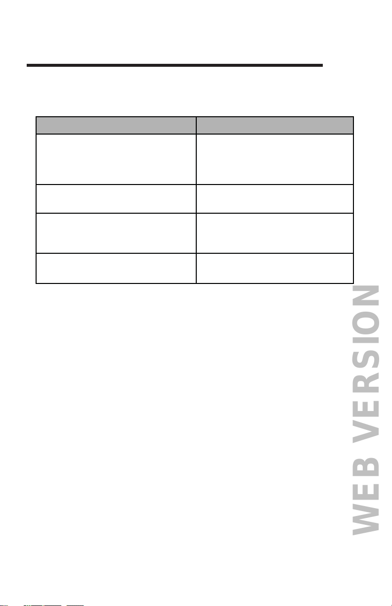
Action Result
• Install Jumper JP1 on
ANA2DMX PCB.
This puts processor in channel
mode.
• Dial up the starting address on
rotary switches SW1, SW2, and
SW3.
This selects the DMX start
address for fader A1.
• For fader channel single pattern
operation, remove JP4.
Faders 1-6 will respond to DMX
channels 1-6 (assuming start
address = 001).
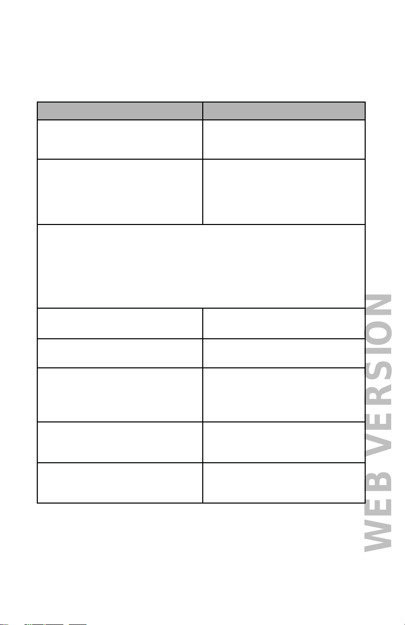
• For fader channel dual wrap
around pattern operation, install
JP4.
Fader 1 controls DMX channels 1
and 7;
Fader 2 controls DMX channels 2
and 8;
Fader 3 controls DMX channels 3
and 9;
Fader 4 controls DMX channels 4
and 10;
Fader 5 controls DMX channels 5
and 11;
Fader 6 controls DMX channels 6
and 12
(assuming start address = 001
and 6 channel operation -
see JP6).
• For highest takes precedence
fader operation, remove JP5.
The fader channels will pile onto
the appropriate incoming DMX
channel levels.
• To replace the incoming DMX
channel levels with the fader
levels, install JP5.
The fader channels will replace
the appropriate incoming DMX
channel levels.
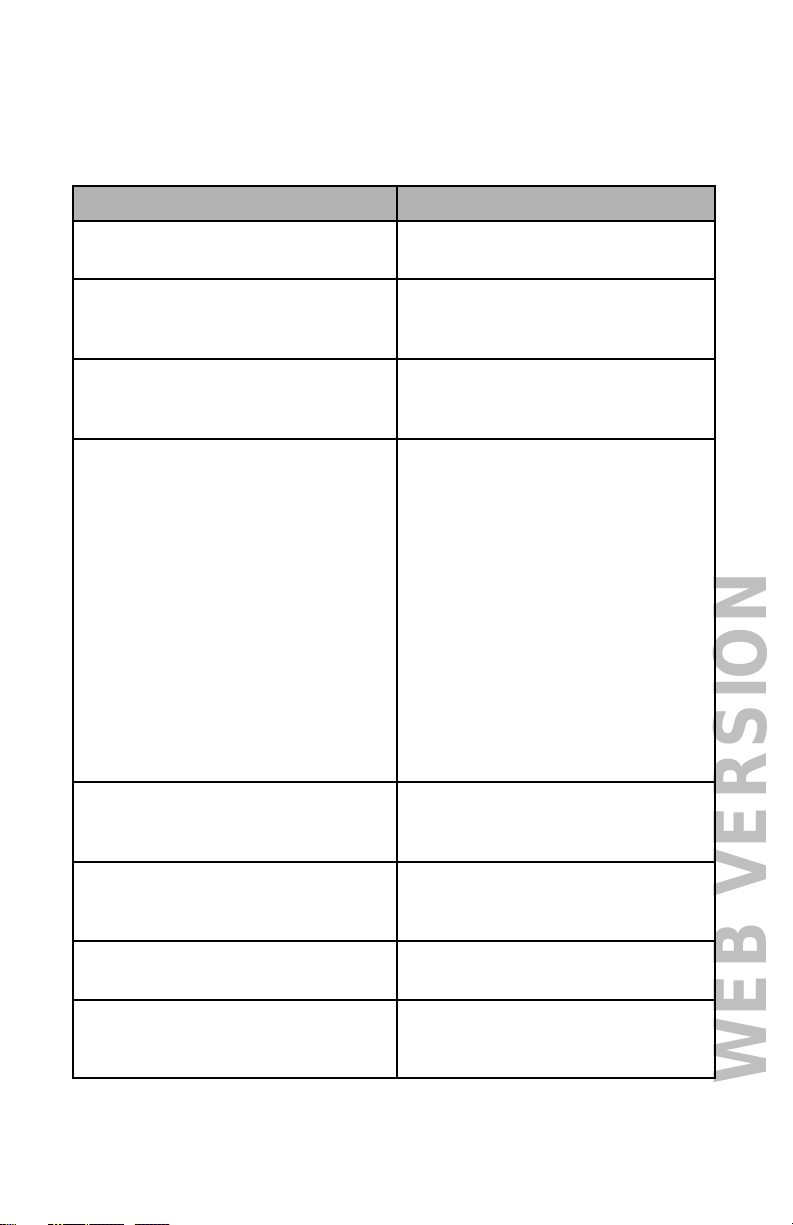
• For 4 channel operation install
JP6 on ANA2DMX Processor.
This puts the processor in 4
channel wrap around mode.
• For 6 or 12 channel operation
remove JP6 on ANA2DMX
Processor.
This puts the processor in 6
channel wrap around mode.