manuals.online logo
Brands
  1. Home
  2. •
  3. Brands
  4. •
  5. Leviton
  6. •
  7. Switch
  8. •
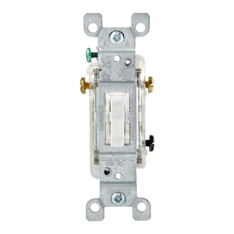
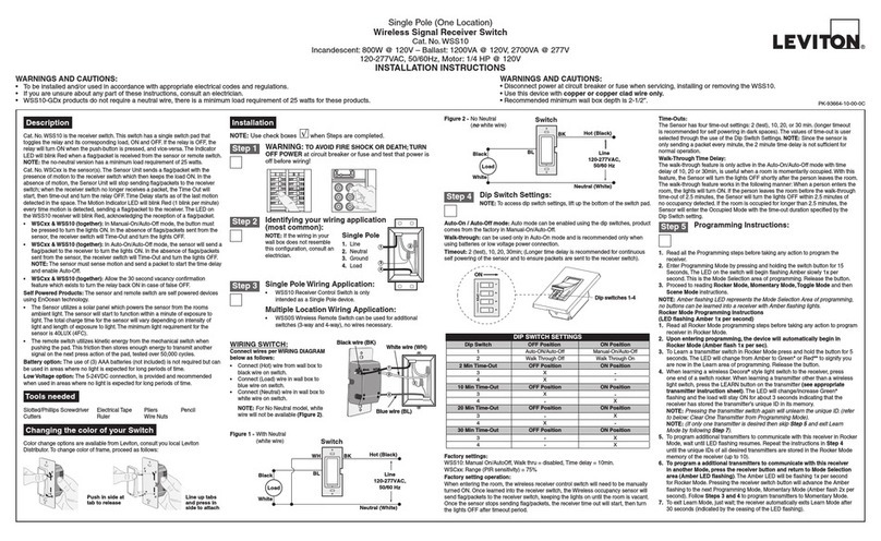
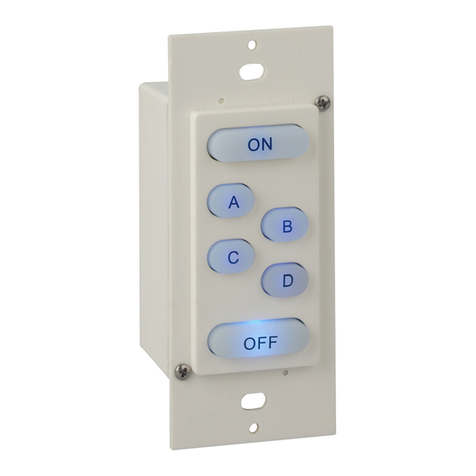
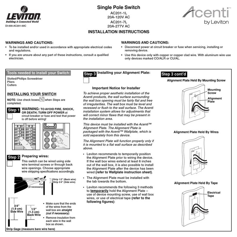
  9. Leviton Lumina RF 10A User manual

Leviton Lumina RF 10A User manual

INSTALLATION AND QUICK START SHEET ENGLISH
WARNINGS AND CAUTIONS
• TO AVOID FIRE, SHOCK, OR DEATH;TURN OFF POWER at circuit breaker or fuse and
test that power is off before wiring!
• To be installed and/or used in accordance with appropriate electrical codes and regulations.
• If you are unsure about any part of these instructions, consult an electrician.
WARNINGS AND CAUTIONS
• This product must be installed in a suitable junction box or equivalent enclosure.
• Use this device with copper or copper-clad wire only.
• For indoor use only.
• SAVE THESE INSTRUCTIONS.
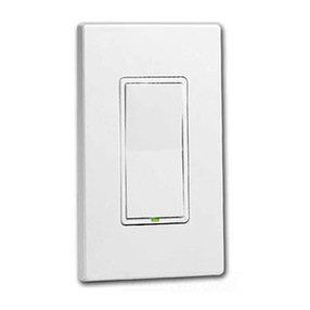
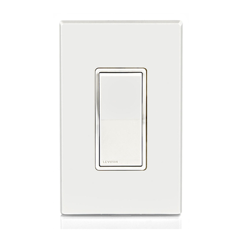
LEVITON lumina™ RF 10A RELAY SWITCH
Cat. No. ZSS10-NAZ
Rating: 120-277VAC, 50/60Hz,
Incandescent: 800W @ 120V - Ballast: 1200VA @ 120V, 2700VA @ 277V - Motor: 1/4HP @ 120V DI-XXX-ZSS10-00A
For the following models:
ZSS10-NAZ:
• 10A robust/commercial mechanical latching relay to handle high inrush (LED) and large loads.
• Utilizes Leviton lumina™ RF technology to communicate with other lumina™ RF wireless
compatible products.
NOTES
• Requires a neutral (white) connection wire.
• Requires lumina™ gateway for programming and control communication to other devices.
Leviton lumina™ RF Wall Switch Overview
Leviton’s lumina™ RF components are designed to communicate with each other via 2.4GHz Radio
Frequency (RF) to provide remote control of your lighting. Each module in Leviton’s lumina™ RF component
line is designed to act as a router. These routers will re-transmit the RF signal from one device to another
until the intended device is reached. This ensures that the signal is received by its intended device by routing
the signal around obstacles and radio dead spots.
Figure 1 - Leviton lumina™ RF Wall Switch
(ON)
(OFF)
BOTTOM
LED
INDICATOR
TOP
BLUE
WHITE
LOAD
NEUTRAL
BLACK LINE
Changing Switch Color
The color of the Leviton lumina™ RF Wall Switch may be changed to complement the interior décor. The Leviton
lumina™ RF Wall Switch is supplied with a white, ivory and light almond switch plate. Additional colors are available;
contact your Leviton distributor for more information. When changing the switch plate, make sure that the switch
is disconnected from all power, and proceed as follows:
Figure 2 – Changing Switch Color
1. Push in side at tab to release (see Figure 2).
2. Line up and press in side to attach (see Figure 2).
The Leviton lumina™ RF Wall Switch is wired directly to the load and utilizes a mechanical latching relay for power
switching control from the Decora® rocker. When multiple wall switches are controlling the same load, the following
wiring instructions apply to each wall switch and the multi-location load control is completed through programming
via the Leviton lumina™ gateway. A gateway is required for all lumina™ RF Wall Switches control programming,
please refer to the lumina™ gateway user manual for details.
NOTES:
1. Refer to Figure 1 to determine the wire colors for each connection.
2. Leviton lumina™ RF Wall Switch requires a neutral (white) connection.
3. Wiring Connections:
a. Connect the Load (blue) wire to the lighting load.
b. Connect the Neutral (white) wire to the neutral supply.
c. Connect the Line (black) wire to either phase of the 120-277V supply.
The Line (black) wire must be accessible for the installation of any additional switches.
Installation Procedure
1. Be sure that all power to the load has been disconnected by turning off the circuit breaker.
2. If applicable, remove the faceplate from the existing wall switch, remove the existing wall switch from the wall box, and
disconnect the wires from the existing wall switch. Identify the “Line”, “Neutral”, “Load” and “Traveler” (if applicable) wires.
3. Remove 3/4” of insulation from each of the wires on the Leviton lumina™ RF Wall Switch. Install the Leviton lumina™ RF Wall
switch by connecting wires per wiring configuration (see Figure 3).
4. After all connections have been made, be certain that all wire connectors are firmly attached and there is no exposed copper.
5. Gently place the wires and Leviton lumina™ RF Wall Switch into the wall box with the LED at the top of device. Using the
supplied screws, attach the Leviton lumina™ RF Wall Switch to the wall box.
6. Before installing the faceplate, restore power to the circuit, and verify LED, switch On/Off operation.
7. After testing the Leviton lumina™ RF Wall Switch and Multi-location Switches for proper local operation (see Table 1),
install a Decora® faceplate over each switch.
Leviton 10A RELAY SWITCH OPERATION
Local Rocker Switch Operation
The Leviton 10A Relay Switch has a rocker switch that can be used to control the load (see Table 1).
LED Indicator
The Leviton lumina™ RF Wall switch comes equipped with a LED indicator that is normally lit to green
when the load is off. The LED is off when the load is on.
Setup Mode for Controls Communication
Configure the Leviton lumina™ RF Wall Switch using a lumina™ gateway with a PC running the lumina™ RF
smart configuration software (see configuration videos and software for detailed radio frequency pairing
and control programming online at www.leviton.com/luminarf). The device must be in Network Enrollment
mode while the lumina™ gateway is searching for new devices to Enroll.
Table 1 -
Leviton lumina™ RF 10A Relay Switch Local Operation
Rocker Event Top Rocker Bottom Rocker
Single-Tap Load turns on. Load turns off.
BK
WH
BL
Switch
Black
White
Load
Neutral (White)
Line
120-277VAC, 50/60Hz
Hot (Black)
Figure 3 - Wiring
Push in side at
tab to release Line up tabs
and press in
side to attach
NOTE: Traveler wire is not required for multi-location load control, firmly attach wire connector and tuck into wall box.
WIRING INSTRUCTIONS
ForTechnical Assistance Call: 800-824-3005 - www.leviton.com
© 2014 Leviton Mfg.Co., Inc. DI-XXX-ZSS10-00A
LEVITON LIMITEDWARRANTY
Leviton warrants to the original consumer purchaser and not for the of anyone else that products manufactured by Leviton under the Leviton brand name (“Product”) will be free from defects
in material and workmanship for the time periods indicated below, whichever is shorter: • OmniPro II and Lumina Pro: three (3) years from installation or 42 months from manufacture date.
• OmniLT, Omni IIe, and Lumina: two (2) years from installation or 30 months from manufacture date. • Thermostats, Accessories: two (2) years from installation or 30 months from manufacture date.
• Batteries: Rechargeable batteries in products are warranted for ninety (90) days from date of purchase. Note: Primary (non-rechargeable) batteries shipped in products are not warranted.
Products with Windows®Operating Systems: During the warranty period, Leviton will restore corrupted operating systems to factory default at no charge, provided that the product has been used as
originally intended. Installation of non-Leviton software or of the operating system voids this warranty. Leviton’s obligation under this Limited Warranty is limited to the repair or replacement,
at Leviton’s option, of Product that fails due to defect in material or workmanship. Leviton reserves the right to replace product under this Limited Warranty with new or remanufactured product.
Leviton will not be responsible for labor costs of removal or reinstallation of Product.The repaired or replaced product is then warranted under the terms of this Limited Warranty for the remainder of
the Limited Warranty time period or ninety (90) days, whichever is longer. This Limited Warranty does not cover PC-based software products. Leviton is not responsible for conditions or applications
beyond Leviton’s control. Leviton is not responsible for issues related to improper installation, including failure to follow written Installation and operation instructions, normal wear and
tear, catastrophe, fault or negligence of the user or other problems external to the Product. To view complete warranty and instructions for returning product, please visit us at www.leviton.com.
FOR CANADA ONLY
For warranty information and/or product returns,
residents of Canada should contact Leviton in writing
at Leviton Manufacturing of Canada Ltd to the
attention of the Quality Assurance Department, 165
Hymus Blvd, Pointe-Claire (Quebec), Canada H9R
1E9 or by telephone at 1 800 405-5320.
Use herein of third party trademarks, service marks,
trade names, brand names and/or product names
are for informational purposes only, are/may be the
trademarks of their respective owners;such use is not
meant to imply sponsorship, or endorsement.
Mode/
Blink(s) Operation
1
Enroll - Allows device to enroll in a network.
2Identify - The device will announce itself to
other devices on the network. (FUTURE USE)
Table 2 - Operation Modes - Defined
3Pairing - Will initiate a search for compatible
devices that are in Identify Mode. (FUTURE USE)
4LED Operation - Allows the device to
enable/disable all LED operations.
Mode 2
Two Blink - RF Identify.
Mode 3
Future Use
Press and hold either top or bottom button for > 5 seconds to enter “60 second RF identify room devices”.
Three Blink - RF Pairing, Link.
[Start red blinking until complete (time out or press of bottom button) then return to Mode 3 - Three Blink].
Press and hold bottom button for > 5 seconds to initiate a search for compatible room devices currently in the RF identify
mode.
5Reset to Factory Default - Resets device to
Factory Default settings.
FCC COMPLIANCE STATEMENT:
Contains FCC ID: W7Z-ZICM357SP0
The enclosed device complies with Part 15 of the FCC Rules.
Operation is subject to the following two conditions:
(i.) This device may not cause harmful interference
(ii.) This device must accept any interference received,
including interference that may cause undesired operation.
Any changes or modifications not expressly approved by
Leviton could void the user’s authority to operate this
equipment. This equipment has been tested and found to
comply with the limits for a Class B digital device, pursuant
to part 15 of the FCC Rules. These limits are designed to
provide reasonable protection against harmful interference
in a residential installation. This equipment generates uses
and can radiate radio frequency energy and, if not installed
and used in accordance with the instructions, may cause
harmful interference to radio communications. However,
there is no guarantee that interference will not occur in a
particular installation. If this equipment does cause harmful
interference to radio or television reception, which can be
determined by turning the equipment off and on, the user is
encouraged to try to correct the interference by one or more
of the following measures:
• Reorient or relocate the receiving antenna.
• Increase the separation between the equipment and receiver.
• Connect the equipment into an outlet on a circuit different
from that to which the receiver is connected.
• Consult the dealer or an experienced radio/TV technician for help.
INDUSTRY CANADA COMPLIANCE STATEMENT:
Contains IC: 8254A-ZICM357SP0. This device complies with Industry Canada license-exempt RSS standard(s). Operation
is subject to the following two conditions: (1) this device may not cause interference, and (2) this device must accept any
interference, including interference that may cause undesired operation of the device. IMPORTANT! Any changes or
modifications not expressly approved by the party responsible for compliance could void the user’s authority to operate
this equipment. This Class B digital apparatus complies with Canadian ICES-003.
SPECIFICATIONS
Number ZSS10-NAZ
LED, Incandescent, Inductive,
and Fluorescent Loads
Yes
Motor-Operated Appliances Yes
Current Maximum 10A
Connections
16 AWG
LED Indicator Yes
Dimensions 4.1” x 1.75” x 1.45”
Weight 0.25 lb.
Mounting Standard J box
Input Power 120-230-277 VAC
Input Frequency 50/60Hz
Power Consumption 120VAC @ 3.4mA AC
(160mW typical)
277VAC @ 3.6mA AC
(420mW typical)
Operating Temperature -40°F to 104°F
Enter Menu
Pressing and holding the bottom (off) button for > 10 seconds [Identified by the LED switching to an amber blinking].
Step 1
Step 2
Table 4 - Configuration Menu: Reset to Factory Default Settings
Tap bottom button 4 times to move into Five Blink (Mode 5 - Reset to Factory Default).
Press and hold bottom button for > 5 seconds to enter factory default pending mode.
[Start red blinking until top button pressed to initiate - to cancel Factory Reset: press the bottom button or allow idle time out].
Press and hold top button for > 5 seconds to complete the factory default reset process.
[Stops the red blinking, cancel the menu and return to normal device operation when reset is complete].
Step 3:
Reset/Exit
NOTE: If your ZSS10 is not responding, or you are unable to control it after you have tried to Include/Exclude it multiple times, it
may be necessary to reset the device to its original factory settings. To accomplish this, refer to the “Reset to Factory Default
Settings” section of the instructions. Once the ZSS10 is reset, it will be necessary to Re-enroll it to a network before it can be used.
Notes
Mode 1: Enrolling Your Device In RF Network
Enter Menu
Table 3 - Configuration Menu, Quick Start Programming
Requires lumina™ gateway - review all related gateway instructions before beginning.
Idle Time Exit: no button presses for > 20 seconds will time out the menu and return to normal operation.
Press and hold the bottom (off) button for > 10 seconds [Identified by the LED switching to an amber blinking].
(Mode 1 - One Blink - Enroll into RF Network).
Review lumina™ gateway instructions, power up gateway and prepare network.
Step 3: Exit Tap the top button.
Mode 1: Removing Your Device From RF Network
Enter Menu
Step 1:
Remove
Device
Tap the top button.
Press and hold bottom button for > 5 seconds to enroll into lumina™ RF network.
Step 1
Step 2:
Add Device [Start red blinking until complete (time out or press of bottom button) then return to Mode 1 - One Blink].
Press and hold the bottom (off) button for > 10 seconds [Identified by the LED switching to an amber blinking].
(Mode 1 - One Blink - Enroll into RF Network).
Press and hold the top button for > 5 seconds to leave the network.
[Start red blinking until complete (time out or press of bottom button) then return to Mode 1 - One Blink].
Step 3: Exit
Mode 4: Turn LED OFF/ON
Enter Menu Press and hold the bottom (off) button for > 10 seconds [Identified by the LED switching to an amber blinking].
(Mode 1 - One Blink - Enroll into RF Network).
Step 3: Exit
Step 1
Step 2
Tap bottom button 4 times to move into Four Blink (Mode 4 - LED Operation).
Press and hold top button for > 5 seconds to toggle between always off (red blink) and normal locator operation (green blink).
Tap the top button.
(Mode 1 - One Blink - Enroll into RF Network).
[Start red blinking until complete (time out or press of bottom button) then return to Mode 2 - Two Blink].
Tap bottom button to move into Three Blink (Mode 3 - RF Pairing, Link).
Press and hold top button for > 5 seconds to clear out the list of paired devices.
Tap bottom button to move into Four Blink (Mode 4 - Reset to Factory Default).
09/04/2014

Other Leviton Switch manuals

Leviton powerswitch MDS3 User manual

Leviton

Leviton powerswitch MDS3 User manual

Leviton Decora IPV0R User manual

Leviton

Leviton Decora IPV0R User manual

Leviton 321 User manual

Leviton

Leviton 321 User manual

Leviton OSSNL-ID User manual

Leviton

Leviton OSSNL-ID User manual

Leviton powerswitch MDS3-AC User manual

Leviton

Leviton powerswitch MDS3-AC User manual

Leviton decora plus A5621 User manual

Leviton

Leviton decora plus A5621 User manual

Leviton POENS-8PT User manual

Leviton

Leviton POENS-8PT User manual

Leviton Powerswitch MDS30-AX User manual

Leviton

Leviton Powerswitch MDS30-AX User manual

Leviton LIT-32712-00 User manual

Leviton

Leviton LIT-32712-00 User manual

Leviton 1221-2KL User manual

Leviton

Leviton 1221-2KL User manual

Leviton decora plus 56021 User manual

Leviton

Leviton decora plus 56021 User manual

Leviton PowerSwitch DS30-AX User manual

Leviton

Leviton PowerSwitch DS30-AX User manual

Leviton decora smart DW15S User manual

Leviton

Leviton decora smart DW15S User manual

Leviton 5655 User manual

Leviton

Leviton 5655 User manual

Leviton Decora 6696 User manual

Leviton

Leviton Decora 6696 User manual

Leviton 47691-3MS User manual

Leviton

Leviton 47691-3MS User manual

Leviton 35A00-1 Mounting instructions

Leviton

Leviton 35A00-1 Mounting instructions

Leviton 1754 User manual

Leviton

Leviton 1754 User manual

Leviton 1755 User manual

Leviton

Leviton 1755 User manual

Leviton 83A00-1 User manual

Leviton

Leviton 83A00-1 User manual

Leviton 1080 Instruction manual

Leviton

Leviton 1080 Instruction manual

Leviton OMNI-BUS Mounting instructions

Leviton

Leviton OMNI-BUS Mounting instructions

Leviton Scene Capable Electronic Switch User manual

Leviton

Leviton Scene Capable Electronic Switch User manual

Leviton VSHUB User manual

Leviton

Leviton VSHUB User manual

Popular Switch manuals by other brands

CYP CM-345TP Operation manual

CYP

CYP CM-345TP Operation manual

VIA Technologies PWVIA DIN P16 installation guide

VIA Technologies

VIA Technologies PWVIA DIN P16 installation guide

SMC Networks ISE35 Operation manual

SMC Networks

SMC Networks ISE35 Operation manual

Huawei B882 Getting started guide

Huawei

Huawei B882 Getting started guide

Arista 7000 Series quick start guide

Arista

Arista 7000 Series quick start guide

MFJ Enterprises MFJ-4716 instruction manual

MFJ Enterprises

MFJ Enterprises MFJ-4716 instruction manual

Siemens N 523/02 Technical product information

Siemens

Siemens N 523/02 Technical product information

National Instruments cRIO-9805 Getting started guide

National Instruments

National Instruments cRIO-9805 Getting started guide

Siemens SCALANCE XB-200 Configuration manual

Siemens

Siemens SCALANCE XB-200 Configuration manual

PTN WVG2AL USB user manual

PTN

PTN WVG2AL USB user manual

Perle IDS-509-2SFP Hardware installation guide

Perle

Perle IDS-509-2SFP Hardware installation guide

Cisco Nexus 9332D-GX2B Hardware installation guide

Cisco

Cisco Nexus 9332D-GX2B Hardware installation guide

Dicota Branch Power 2.0 user guide

Dicota

Dicota Branch Power 2.0 user guide

Draytek VigorSwitch G2280 quick start guide

Draytek

Draytek VigorSwitch G2280 quick start guide

Humandata USB-203 user manual

Humandata

Humandata USB-203 user manual

Chenzhu CZ2047 user manual

Chenzhu

Chenzhu CZ2047 user manual

QNAP QSW-M3212R user guide

QNAP

QNAP QSW-M3212R user guide

Hall Research Technologies UHB-SW2 user manual

Hall Research Technologies

Hall Research Technologies UHB-SW2 user manual

manuals.online logo
manuals.online logoBrands
  • About & Mission
  • Contact us
  • Privacy Policy
  • Terms and Conditions

Copyright 2025 Manuals.Online. All Rights Reserved.