Levitronix PuraLev 2000SU User manual

User Manual for PuraLev®2000SU
www.levitronix.com
PL-4034-00, Rev02, DCO# 20-144
First Release: 20-Apr-2012
Last Update: 09-Jul-2020
PuraLev®2000SU
4.3 bar (62.4 psi)
140 liters/min (37 gallons/min)
USER MANUAL
This manual contains information necessary for the safe and proper use of the PuraLev®2000SU. Included are
specifications for the standard configurations of the pump system and instructions regarding its use, installation,
operation, adjustment, inspection and maintenance. For special configurations of the pump system refer to
accompanying information. If the system must be configured for other parameter settings, then the Levitronix®Service
Software version V2.0.5.0 or higher (with according manual Levitronix
Doc.# PL-4046-00) is necessary. Familiarize
yourself with the contents of the manual to ensure the safe and effective use of this product. After reading this
manual, please store the manual where the personnel responsible for operating the pump system can readily refer to
it at any time.

User Manual for PuraLev®2000SU
www.levitronix.com
PL-4034-00, Rev02, DCO# 20-144
2
Table of Content
1SAFETY PRECAUTIONS ..........................................................................................................................................3
2SPECIFICATIONS .....................................................................................................................................................4
2.1 Specification of Components.............................................................................................................................4
2.2 Standard System Configurations.......................................................................................................................6
2.3 General Environmental Conditions....................................................................................................................7
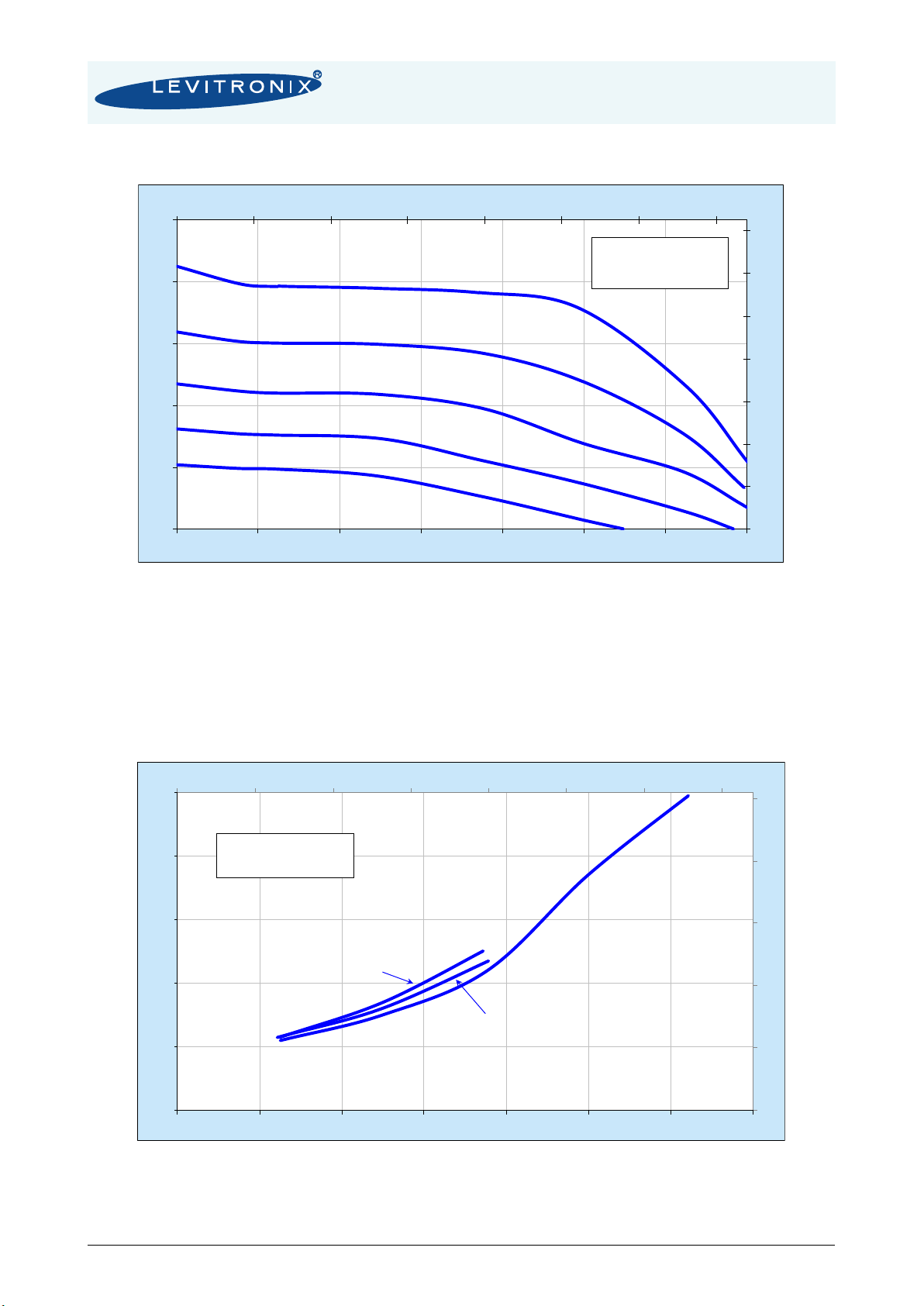
2.4 Pressure-Flow Curves.......................................................................................................................................8
2.5 NPSHr Curves...................................................................................................................................................8
2.6 Maximum Static Pressure for Pump Heads.......................................................................................................9
2.7 Basic Dimensions of Main Components..........................................................................................................10
3ENGINEERING INFORMATION..............................................................................................................................12
3.1 Material and Sealing Concept..........................................................................................................................12
3.2 AC Supply and Power Consumption................................................................................................................13
3.3 Temperature Monitoring ..................................................................................................................................14
3.4 Thermal Management......................................................................................................................................15
3.5 Hydraulic Circuit Design ..................................................................................................................................19
4INSTALLATION.......................................................................................................................................................20
4.1 Electrical Installation of Controller....................................................................................................................20
4.2 Mechanical Installation of the Motor ................................................................................................................26
4.3 Mechanical Installation of the Controller..........................................................................................................28
4.4 Mechanical Installation of Adaptor/Extension Cables......................................................................................29
4.5 System Operation with LPC-2000.1 (Stand-Alone Version) ............................................................................30
4.6 System Operation with Controller LPC-2000.2 (PLC version) .........................................................................33
4.7 System Operation for ATEX / IECEx Applications...........................................................................................35
5INSTRUCTIONS FOR USE OF PUMP HEAD .........................................................................................................36
5.1 Description and Preparation ............................................................................................................................36
5.2 General Warnings and Cautions......................................................................................................................36
5.3 Mounting of Pump Head..................................................................................................................................37
5.4 Removal of Pump Head...................................................................................................................................37
5.5 Assembly into Circuit.......................................................................................................................................37
6TROUBLESHOOTING.............................................................................................................................................38
6.1 Troubleshooting for Operation with Controller LPC-2000.1.............................................................................38
6.2 Troubleshooting for Operation with Controller LPC-2000.2.............................................................................38
6.3 Troubleshooting with Levitronix®Service Software..........................................................................................38
7TECHNICAL SUPPORT ..........................................................................................................................................38
8APPENDIX...............................................................................................................................................................39
8.1 Regulatory Status............................................................................................................................................39
8.2 Symbols and Signal Words..............................................................................................................................42

User Manual for PuraLev®2000SU
www.levitronix.com
PL-4034-00, Rev02, DCO# 20-144
3
1 Safety Precautions
The PuraLev®2000SU pump system is designed to be used in industrial production machines and
equipment containing hydraulic circuits. Typical applications are Pharmaceutical and Bioprocessing
equipment. Installation shall be done by qualified personnel only. Following safety precautions and all
“CAUTION”, “WARNING” and “DANGER” indications in the relevant sections shall be followed.
CAUTION
Do not under any circumstances open the controller or motor. Levitronix®does not
assume responsibility for any damage, which occurs under such circumstances.
CAUTION
High magnetic field strength of pump impeller.
The pump system contains a rotor magnet with high field strength. This may alter
or damage the calibration of sensitive electronic devices and measuring
instruments in the immediate surroundings. Keep at a safe distance from the rotor,
computers, monitors and all magnetic data storage media (e.g. disks, credit cards,
audio, video tapes etc.)
!
WARNING
Hazardous voltage may be present.
The controller must be grounded and placed in a spill protected electrical cabinet.
Do not under any circumstances open the powered controller.
Always isolate the electrical power supply before making or changing connections
to the unit. To remove the power it is recommended to use an isolating device.
Hazardous voltage is present until 20 sec after switch off. Do not handle the
controller during this time.
!
WARNING
High magnetic field strength of pump impeller.
The pump system contains a rotor magnet with high field strength. Pace maker
may be influenced and magnetic forces may lead to contusions. Keep distance to
pace makers and handle impeller with care.
!
WARNING
TOXIC CHEMICALS may be present.
When using the system to pump chemicals skin contact and toxic gases may be
hazardous to your health. Wear safety gloves and other appropriate safety
equipment.
!
WARNING
Motors for ATEX / IECEx applications: only specific types of motors LPM-2000 are
classified for the use in ATEX Zone 2 classified locations. Refer to the
corresponding section in the manual.
!
WARNING
Do not miss-match the power extension cables for connection of the motor to the
controller of the BPS- PuraLev®2000SU as
this may destroy the controller. The BPS-4 power extension cables are designated
-PuraLev®2000SU -.

User Manual for PuraLev®2000SU
www.levitronix.com
PL-4034-00, Rev02, DCO# 20-144
4
2 Specifications
2.1 Specification of Components
Figure 1 shows the main system components (motor, controllers, and pump head) and Figure 2 illustrates
the accessories.
Figure 1: Pump system with standard components
Figure 2: Pump System Accessories
2a
4a
4b
1
2b
3
1
3

User Manual for PuraLev®2000SU
www.levitronix.com
PL-4034-00, Rev02, DCO# 20-144
5
System Name
Article #
Pump Head
Socket
Motor
Controller
Note
PLD-2000SU.1
100-90726
PHS-2000.2
LPM-2000.7
LPC-2000.1-04
Adaptor/Extension (0.5 - 10m) cables according to Table 3 (Position 4a and
4b) have to be ordered as separate article with specified length.
ATEX Cable Sealing System can be ordered according to Table 4 (Pos. 7)
Certifications: CE, IECEE (CB scheme), ETL (NRTL), ATEX and IECEx ->
see Section 8.1
PLD-2000SU.2
100-90727
LPM-2000.7
LPC-2000.2-04
PLD-2000SU.3
100-90729
LPM-2000.8
LPC-2000.1-04
PLD-2000SU.4
100-90730
LPM-2000.8
LPC-2000.2-04
Table 1: Standard system configurations
Pos.
Component
Article Name
Article #
Characteristics
Value / Feature
1a
Single-Use
Pump Head
DCP-2000.2
100-90889
Impeller / Pump Housing
In-/Outlet Fittings
Polypropylene (FDA, USP Class VI, BSE/TSE/Animal free)
(ASME BPE 2009)
Max. Flow
Max. Diff.-Pressure
Max. Viscosity
140 liters/min / 37 gallons/min
4.3 bar / 62.4 psi
50 cP (preliminary Information)
Wet Pump Volume
270 ml / 630 cm2
Max. Liquid Temp.
600C / 1400F
Sterilization Methods
Gamma sterilization with doses up to 40 kGy
1b
Irradiated Pump
Head
DCP-2000.2-G25
100-91080
Applied Gamma Dosage
2a
Motor
(ATEX, IECEx)
LPM-2000.7
100-10059
Housing
- Epoxy (anti-corrosive) coated Aluminum
- waterproofed (IP67)
Cable / Connectors
2x 3m cables with PVC jacket / 2x circular (M23, IP-67)
ATEX/IECEx Marking
II 3G Ex ec h IIC T5 Gc
II 3D Ex h tc IIIC T100°C Dc
2b
Motor
(ATEX, IECEx)
LPM-2000.8
100-10060
Housing
- ETFE (chemical resistant) coated Aluminum
- waterproofed (IP67)
Cable / Connectors
2x 3m cables with FEP jacket / 2x circular (M23, IP-67)
3
Pump Head
Socket
PHS-2000.2
100-90891
Mounting Type
Mounting with 4x M8 screws
Material
Anodized Aluminum
4a
Standalone
Controller
(User Panel)
LPC-2000.1-04
100-30064
(Supply and
Enable
connector
included)
Voltage / Power
1 x 200-240 V AC
10% / 2kW @ 50/60Hz
3 x 200-240 V AC
10% / 2kW @ 50/60Hz
See Section 3.2 for details.
Housing Protection
IP20
Interfaces for
Standalone Controller
Panel to set speed (automatic storage on internal EEPROM)
PLC with
1x analog 4 - 20 mA
0 - 24 V (optocoupler)
0 - 24 V (relais)
Standard Firmware
E4.25
4b
Extended
Controller
(PLC and USB)
LPC-2000.2-04
100-30065
(Supply and PLC
connector
included)
Interfaces for
Extended Controller
PLC with
- up to 4 digital inputs 0 - 24V (optocoupler)
- up to 4 digital outputs 0 - 24 V (relais)
- up to 2 analog inputs 4 - 20mA
- up to 2 analog inputs 0 10 V
- up to 2 analog outputs 0 5 V
USB interface (for service and system monitoring)
Standard Firmware
E4.48
Table 2: Specification of standard components
Pos.
Component
Article Name
Article #
Characteristics
Value / Feature
5a
Extension Adaptor
Cable for Sensors
MCAS-600.2-05 (0.5m)
MCAS-600.2-30 (3m)
MCAS-600.2-50 (5m)
MCAS-600.2-70 (7m)
MCAS-600.2-100 (10m)
190-10226
190-10238
190-10127
190-10105
190-10239
Jacket Material
Connectors
PVC
Circular Wallmountable, Metallic (IP-67) to D-SUB
5b
Extension Adaptor
Cable for Power
MCAP-2000.2-05
MCAP-2000.2-30
MCAP-2000.2-50
MCAP-2000.2-70
MCAP-2000.2-100
190-10213
190-10215
190-10216
190-10217
190-10218
Jacket Material
Connectors
PVC
Circular Wallmountable, Metallic (IP-67) to COMBICON
Table 3: Specification of adaptor/extension cables
Pos.
Component
Article Name
Article #
Characteristics
Value / Feature
6a
Air Cooling Module
ACM-4.2
190-10139
Material / Connection Port
Air Pressure
~1 - 3 bar (14 43 psi)
6b
Air Cooling Module
ACM-4.3
190-10243
Material
PP-EL-S with conductive additive for operation with ATEX motor
7a
Fan Cooling Module
FCM-2000.1
190j-10390
Housing / Cable Spec.
Supply Spec. / IP Rating
PP (+20% Talkum) white / PP jacket, 3m, circular sealed M12 connector (PP).
24 VDC, 33.5 W / IP-65 (fan is IP68 rated).
7b
Fan Cool. Module
Cable
FCC-1.1-50 (5 m)
FCC-1.1-100 (10 m)
190-10407
190-10408
Specification
PP cable jacket with circular M12 connector (PP) to open wires
8
(A-F)
ATEX Cable
Sealing System
ACS-A.1
(Roxtec)
100-90292
Sleeve (A) and Gasket (B)
Frame (C)
2x Cable Module (D)
Stainless Steel and EPDM
Roxylon (EPDM rubber)
Note:
Lubricant (E) and measurement plates
(F) are included.
Table 4: Specification of accessories

User Manual for PuraLev®2000SU
www.levitronix.com
PL-4034-00, Rev02, DCO# 20-144
6
2.2 Standard System Configurations
2.2.1 Stand-Alone System Configuration
The stand-alone configuration of the PuraLev®2000SU pump system (see Figure 3) consists of a controller
with an integrated user panel to set the speed manually. The speed is automatically stored in the internal
EEPROM of the controller. As an option, the speed can also be set with an analogue signal.
Figure 3: System configuration for standalone operation
(Speed setting with integrated user panel)
2.2.2 Extended System Configuration
The extended version of the PuraLev®2000SU pump system (Figure 4) consists of a controller with an
extended PLC interface. This allows setting the speed by an external signal (see Position 3b in Table 2) and
enables precise closed-loop flow or pressure control in connection with either a flow or a pressure sensor. A
USB interface allows communication with a PC in connection with the Levitronix®Service Software. Hence
parameterization, firmware updates and failure analysis are possible.
Figure 4: Extended operation (flow or pressure control) with extended controller
Chemical Resistance and IP67 Space
Disposable
Pump Head
Motor
Fluid In
Fluid Out
Motor Sensor Cable
Motor Power Cable
Adaptor/Extension
Cable for Sensors
Adaptor/Extension
Cable for Power
Controller
for
Standalone
Operation
Stand Alone
Operation
Speed Control
PLC Interface
Speed Setting
- 1x Digital Input (Enable)
- 1x Digital Output (Status)
- 1x Analog Input (Speed)
Pumphead Socket
(Mounting with 4x M8 Screws)
3 x AC 200-240V or
1 x AC 200-240V
Chemical Resistance and IP67 Space
Motor
Fluid In
Fluid Out
Motor Sensor Cable
Motor Power Cable
USB
- Service
- Firmware Update
- Configuration etc.
Flow- or
Pressure
Sensor Adaptor/Extension
Cable for Sensors
Adaptor/Extension
Cable for Power
Extended PLC Interface
Speed, Flow
or Pressure Setting
- 4 Digital Inputs
- 4 Digital Outputs
- 4 Analog Inputs
- 2 Analog Outputs
Controller
for
Extended
Operation
Disposable
Pump Head
Pumphead Socket
(Mounting with 4x M8 Screws)
3 x AC 200-240V or
1 x AC 200-240V
2a
4a
1
5a
5b
Motor option with ETFE
coating and FEP cabling
2b
2a
4b
1
5a
5b
Motor option with
ETFE coating and
FEP cabling
2b

User Manual for PuraLev®2000SU
www.levitronix.com
PL-4034-00, Rev02, DCO# 20-144
7
2.2.3 ATEX / IECEx System Configuration
Together with the standard pump-head and controllers an ATEX / IECEx certified motor allows installation of
motor and pump-head within an ATEX Zone 2 area (see Figure 5). The ATEX / IECEx motor (Pos. 2b in in
Table 2) comes delivered with special connectors and according extension cables (Pos. 5a and 5b in Table
3). One option to lead the cables outside of the Ex area is an ATEX certified cable sealing system as listed in
Table 4 (see Pos. 8) and shown in Figure 2.
Figure 5: System configuration for ATEX / IECEx applications
2.3 General Environmental Conditions
Usage
Indoor 1
Altitude
Up to 2000 m
Operating ambient temperature
0 to 40 °C
Storage ambient temperature
(Extremes for Transportation)
-20 to 80 °C
-20 to 70 °C for single-use pump head
Operating humidity range (relative humidity)
15 –95% (non-condensing)
Storage humidity range (relative humidity)
(Extremes for Transportation)
15 –95% (non-condensing)
Normal storage conditions
Ambient temp.: 20 to 30 °C
Relative humidity: 50% (non-condensing)
AC supply fluctuations
10% of nominal voltage
Transient over-voltages typically present on
the mains supply
Surge immunity according to EN 61000-4-5
Pollution degree
2
Table 5: Environmental conditions for pump system
Note 1: Contact Levitronix®technical department (see Section 7) for outdoor usage.
Motor
Fluid In
Fluid Out
Motor Sensor Cable
Motor Power Cable
Adaptor/Extension
Cable for Sensors
Adaptor/Extension
Cable for Power
All
Controller
Types
ATEX conform cable sealing system
Cabinet Boundary for
ATEX Zone 2 Area
ATEX Zone 2 Classified Location
Chemical Resistance and IP-67 Space
Disposable
Pump Head
Pumphead Socket
(Mounting with 4x M8 Screws))
3 x AC 200-240V or
1 x AC 200-240V
2a
4
1
5a
5b
Motor option with ETFE
coating and FEP cabling
2b
8

User Manual for PuraLev®2000SU
www.levitronix.com
PL-4034-00, Rev02, DCO# 20-144
8
2.4 Pressure-Flow Curves
Figure 6: Pressure/flow curves for aqueous liquids
(Measured with pump-head DCP-2000.2)
The linearly increasing cavitation effects flows > 100 l/min and liquid temperature in the range of 90 0C was
measured for water. This can be different for other liquids and depends on the hydraulic circuit design. For
example: higher inlet pressure reduces cavitation effects.
2.5 NPSHr Curves
Figure 7: NPSHr curves for “High Flow” pump head
(Measured with pump-head DCP-2000.2)
0
10
20
30
40
50
60
70
0 5 10 15 20 25 30 35
0.0
1.0
2.0
3.0
4.0
5.0
020 40 60 80 100 120 140
[psi]
[gpm]
[bar]
[lpm]
Specific gravity = 1 g/cm
3
Viscosity = 0.7 cP
Liquid Temp.: 40C
7000 rpm
6000 rpm
5000 rpm
8000 rpm
4000 rpm
0
2
4
6
8
10
0 5 10 15 20 25 30 35
0.0
0.2
0.4
0.6
0.8
1.0
020 40 60 80 100 120 140
[m]
[bar]
[lpm]
Specific gravity = 1 g/cm3
Viscosity = 0.7 cP
Liquid Temp.: 40C
8000 rpm
7000 rpm
6000 rpm

User Manual for PuraLev®2000SU
www.levitronix.com
PL-4034-00, Rev02, DCO# 20-144
9
2.6 Maximum Static Pressure for Pump Heads
Figure 8: Specification for maximum static pressure for single-use pump head DCP-2000.2
(Pressure limits only valid for pump head mounted on motor)
0
20
40
60
80
100
77 87 97 107 117 127 137
0
1
2
3
4
5
6
7
8
25 30 35 40 45 50 55 60
[psi]
[°F]
[bar]
Liquid Temperature in [°C]
Max. Static Pressure for DCP-2000.2
Burstpressureat ambient temperature = 25 C is >15 bar after gammaradiation of 40 kGy
and 2 times temperature cyclingbetween -25 C and +75 C.
Note: Pressurelimit only valid for pumphead mounted on motor. Values only valid after
Gamma radiation doses of < 40 kGy.

User Manual for PuraLev®2000SU
www.levitronix.com
PL-4034-00, Rev02, DCO# 20-144
10
2.7 Basic Dimensions of Main Components
Figure 9: Basic dimensions (in mm and [inch]) of motor LPM-2000.x with pump head DCP-2000.2
(for other configurations refer to according drawings)
Manual Screws (M8)
Inlet
ASME BPE-2009
ID = 22.1mm
Outlet
ASME BPE-2009
ID = 22.1mm
4pcs M8x25mm Inox A4
(for socket fixation)

User Manual for PuraLev®2000SU
www.levitronix.com
PL-4034-00, Rev02, DCO# 20-144
11
Figure 10: Basic dimensions (in mm and [inch]) Motor LPM-2000
with Air Cooling Module ACM-4.2
(Same basic dimenions for ACM-4.3)
Cable
Jacket
Cable OD
Motor Sensor
Cable OD
Motor Power
Minimum Bending Radius
Permanent Installation
Minimum Bending Radius
Sometimes Moved
FEP
6.60 mm
8.40 mm
7x Cable OD
15 x Cable OD
PVC
7.20 mm
11.1 mm
5x Cable OD
11 x Cable OD
Table 6: Specifications for min. bending radius of motor and adaptor cables for LPM-2000
Note: If not mentioned explicitly all the cables are not suited for constant dynamic bending and movement!
Figure 11: Basic dimensions (in mm and [inch]) of LPC-2000.1/2-01 controllers
Controller
LPC-2000.2-xx
Controller
LPC-2000.1-xx
Air Connection Port:

User Manual for PuraLev®2000SU
www.levitronix.com
PL-4034-00, Rev02, DCO# 20-144
12
3 Engineering Information
3.1 Material and Sealing Concept
Figure 12: Sealing and material concept of motor with pump head
(Motors LPM-2000.x with pump head DCP-2000.2 and Pump Head Socket PHS-2000.2)
System
Component
Item
Materials
No
Description
Pump Head
DCP-2000.2
1
Pump housing (lid and bottom)
PP (polypropylene)
2
Impeller
PP (polypropylene)
3
Rotor magnet
Rare-earth material
4
Welding seam (housing lid and bottom)
Infrared welding
Pump Head Socket
PHS-2000.2
5
Pump head socket ring
Anodized Aluminum
6
4x M8x25mm screws for motor mounting
Stainless Steel (INOX A4)
7a
7b
Manual screws for pump head fixation (M8)
Screw holder cord
Stainless Steel (INOX A4)
FPM (= FKM)
Motor
LPM-2000.7
8a
Sealing O-ring and gasket for motor housing
FPM (= FKM)
9a
Cable bushing
PA, cable jacket is PVC
10a
Motor housing (blue)
Epoxy coating, waterproof (IP-67)
Coils and electromagnetic circuit potted with an epoxy
compound (UL94 V0).
Motor
LPM-2000.8
8b
Sealing O-ring and gasket for motor housing
FPM (= FKM)
9b
Cable bushing
FPM, cable jacket is FEP
10b
Motor housing (grey)
ETFE coating, waterproof (IP-67)
Coils and electromagnetic circuit potted with an epoxy
compound (UL94 V0).
Table 7: Materials used in the LPM-2000.x motors, DCP-2000.2 pump head and PHS-2000.2 socket
(For other configurations refer to according specifications and drawings)
3
2
10
7a
1
4
7b
9
5
6
8

User Manual for PuraLev®2000SU
www.levitronix.com
PL-4034-00, Rev02, DCO# 20-144
13
3.2 AC Supply and Power Consumption
3.2.1 Power Consumption
Figure 13: Electrical power consumption for aqueous liquids
(Controller LPC-2000.x with pump-head DCP-2000.2)
3.2.2 AC Input Voltage and Grid Currents
The input grid currents depend on the operational point and the input voltage. As shown in Table 8 maximum
input grid currents are achieved at highest power and lowest voltage. Note that the grid currents also depend
on the impedance of the grid, therefore below values are only typical values.
Phase Type
AC Voltage
AC Input Current
Performance Mode
Single-phase
50/60Hz
200 –240 VAC ±10%
Typical: 12 –8.5 Arms ±10%
Max. 2: 13.3 –11.1 Arms ±10%
Continuous speed and
pressure with maximum
active power.
Three-phase
50/60Hz
Delta voltage 1: 200 –240 VAC ±10%
(180 –264 VAC)
Star voltage 1: 115 –139 VAC ±10%
(104 –153 VAC)
Typical: 3x 7 –5 Arms ±10%
Continuous speed and
pressure with maximum
active power.
Table 8: Voltage and grid current specifications
Note 1: See Figure 24 for visualization of delta and star voltages.
Note 2: Values depend on impedance of grid.
3.2.3 Inrush Current
Various situations have to be considered for the inrush current. The controller has integrated inrush current
limiters, which limit the current during switch-on of the AC power. However, these limiters are not active if the
controller is not completely discharged Table 8 shows the inrush currents during these situations. It has to be
emphasized that these are absolute worst case currents measured with a rigid mains supply at highest input
voltage. In reality these inrush currents might be much smaller.
0 5 10 15 20 25 30 35
0
400
800
1200
1600
2000
020 40 60 80 100 120 140
[gpm]
[Watts]
[lpm]
Specific gravity = 1 g/cm
3
Viscosity = ~ 0.7 cP
Liquid Temp.: 40C
7000 rpm
6000 rpm
5000 rpm
8000 rpm
4000 rpm

User Manual for PuraLev®2000SU
www.levitronix.com
PL-4034-00, Rev02, DCO# 20-144
14
Situation
I2tValue in [A2s]
Peak Value in [A]
Switch-on after complete discharge of controller (> 60 s).
For this case inrush current limiter in the controller are active.
29.3
90
Switch-on after in-complete discharge (< 60 s, worst case)
For this case inrush current limiter in the controller are not active.
350.8
1442
Table 9: Inrush currents for various AC voltage power-off/on situations
(Worst case AC input voltage of 240 V +10%)
3.2.4 Earth Leakage Current
Earth leakage currents have been measured under worst case situation and are
5 mA.
3.2.5 Recommendations for Circuit Breaker Design
The controller contains fuses in all power input lines, which are configured for 20 A (time lag T).
For the selection of external breakers above considerations about AC voltage, grid currents, inrush current
and earth leakage current have to be considered. It is recommended to test the reliability and sensitivity of
the selected breakers with the pump system in the context of the tool, where it is operated. Circuit breaker
types full-filling above considerations have following basic specifications:
- 16 A and D or K tripping characteristics
3.3 Temperature Monitoring
To avoid overheating of the system, the controller and motor temperatures are monitored. If the controller
temperature exceeds 70°C (158°F) or the motor temperature exceeds 90°C (194°F) for a duration of more
than 10 minutes, the system goes into an error state and the pump stops. At 80°C (176 F) controller
temperature or 100°C (212°F) motor temperature, the system stops immediately.
Start
Temperature
Monitoring
WARNING
YES
Temperature
> 70°C ?
Temperature
> 80°C ?
YES
ERROR
Temperature
higher than 70°C
for more than 10
minutes?
NO
ERROR
YES
NO
NO
Start
Temperature
Monitoring
WARNING
YES
Temperature
> 90°C ?
Temperature
> 100°C ?
YES
ERROR
Temperature
higher than 90°C
for more than 10
minutes?
NO
ERROR
YES
NO
NO
Figure 14: Controller temp. monitoring
Figure 15: Motor temp. monitoring

User Manual for PuraLev®2000SU
www.levitronix.com
PL-4034-00, Rev02, DCO# 20-144
15
3.4 Thermal Management
3.4.1 Motor Temperature
The motor temperature depends on the ambient and liquid temperature, as well as on the hydraulic
operation point and the characteristics (viscosity and density) of the liquid. Figure 16 illustrates the
temperature characteristics for aqueous liquids at room temperature. For higher liquid temperatures and
hydraulic operating points active cooling is recommended for example with the Air Cooling Module ACM-4.2
(see Figure 18) or the Fan Cooling Module FCM-2000.1 (see Figure 19).
Figure 16: Temperature curves for the LPM-2000.x motor @ 25 °C liquid temperature
(Temperature is measured inside of the motor, temperature of housing and sensor electronics is significantly below this temperature)
Figure 17: Temperature curves for the LPM-2000.x motor @ 60 °C liquid temperature
(Temperature is measured inside of the motor, temperature of housing and sensor electronics is significantly below this temperature)
77
97
117
137
157
177
197
0 5 10 15 20 25 30 35
25
35
45
55
65
75
85
95
020 40 60 80 100 120 140
[°F]
[gpm]
[°C]
[lpm]
Ambient Temp = 25C
Liquid Temp. = 25C
Specific gravity = 1 g/cm3
Viscosity= 0.7 cP
7000 rpm
6000 rpm
5000 rpm
4000 rpm
8000 rpm
Absolute Temperature Limit
RecommendedOperational Limit
77
97
117
137
157
177
197
0 5 10 15 20 25 30 35
25
35
45
55
65
75
85
95
020 40 60 80 100 120 140
[°F]
[gpm]
[°C]
[lpm]
Ambient Temp = 25C
Liquid Temp. =60C
Specific gravity = 1 g/cm3
Viscosity = 0.7 cP
Temp. Time Constant = ~3 hours
7000 rpm
6000 rpm
5000 rpm
4000 rpm
8000 rpm
Absolute Temperature Limit
Recommended
Operational Limit

User Manual for PuraLev®2000SU
www.levitronix.com
PL-4034-00, Rev02, DCO# 20-144
16
Figure 18: Temperature curves of motor LPM-2000.x with Air Cooling Module ACM-4.2
(Temperature is measured inside of the motor, temperature of housing and sensor electronics is significantly below this temperature)
Figure 19: Temperature curves of motor LPM-2000.x with Fan Cooling Module FCM-2000.1
(Temperature is measured inside of the motor, temperature of housing and sensor electronics is significantly below this temperature)
77
97
117
137
157
177
197
0 5 10 15 20 25 30 35
25
35
45
55
65
75
85
95
020 40 60 80 100 120 140
[°F]
[gpm]
[°C]
[lpm]
Ambient Temp = 25C
Liquid Temp. = 60C
Specific gravity = 1 g/cm3
Viscosity= 0.7 cP
Air cooling with ACM-4.2
Absolute Temperature Limit
RecommendedOperational Limit
7000 rpm
6000 rpm
5000 rpm
8000 rpm
4000 rpm
77
97
117
137
157
177
197
0 5 10 15 20 25 30 35
25
35
45
55
65
75
85
95
020 40 60 80 100 120 140
[°F]
[gpm]
[°C]
[lpm]
Ambient Temp = 25C
Liquid Temp. = 60C
Specific gravity = 1 g/cm3
Viscosity = 0.7 cP
Fan cooling with FCM-2000.1
(~25 C air )
Absolute Temperature Limit
RecommendedOperational Limit
7000 rpm
6000 rpm
5000 rpm
8000 rpm
4000 rpm

User Manual for PuraLev®2000SU
www.levitronix.com
PL-4034-00, Rev02, DCO# 20-144
17
The above curves are measurements of the motor temperature at certain liquid and ambient temperatures.
Equation (Eq. 1) shows how to approximately extimate the motor temperature for other liquid and ambient
temperatures based on these curves.
(
(
(Eq. 1)
Cooling Method
Pump Head Type
Convection
Cooling
Air Cooling Module
ACM-4.2
Fan Cooling
Module FCM-2000.1
DCP-2000 (plastic housing)
0.28
0.29 (at 1 bar)
0.32
Table 10: Temperature gradients liquid/motor
All above presented thermal data are typical values, which are partly based on measurements and partly on
interpolations with a simplified thermal model and are therefore only guideline values and are suitable for a
first layout of the basic thermal concept. It is recommended to check the thermal values with the motor
placed on the final location and under worst case performance conditions of the application.
In order to account for thermal variations (like ambient temperature, closed chemical cabinets or corners
without ventilations) and to not significantly reduce the MTBF of the motor it is recommended to keep about
10 to 20°C safety distance to the absolute thermal limit of the motor (90°C) when designing the thermal
concept of the pump system.

User Manual for PuraLev®2000SU
www.levitronix.com
PL-4034-00, Rev02, DCO# 20-144
18
3.4.2 Controller Temperature
Depending on the ambient temperature and the placement of the controller additional cooling may be
required (see Figure 20). To improve cooling of the controller, place the device into a moving air stream. If
the controller is mounted in a compact area or adjacent to additional heat sources (e.g. a 2nd controller)
ensure that there is sufficient ventilation.
Figure 20: Temperature curves of controller LPC-2000 vs. flow and speed
(for pumping with pump head DCP-2000.2 and motors LPM-2000.x)
The above curves are measurements of the controller temperature at 25°C ambient. Equation (Eq. 2) shows
how to calculate the controller temperature for at other ambient temperatures based on this curve.
(
(Eq. 2)
77
87
97
107
117
127
137
147
157
167
0 5 10 15 20 25 30 35
25
30
35
40
45
50
55
60
65
70
75
020 40 60 80 100 120 140
[°F]
[gpm]
[°C]
[lpm]
Ambient temp. =25C
Specific gravity = 1 g/cm3
Viscosity = 0.7 cP
4000 rpm
Absolute Temperature Limit
8000 rpm

User Manual for PuraLev®2000SU
www.levitronix.com
PL-4034-00, Rev02, DCO# 20-144
19
3.5 Hydraulic Circuit Design
Following general design rules help to operate the pump system optimally considering efficiency, optimum
priming behavior and low shear forces:
1. The general rule for minimum shear forces and optimum priming behavior is to minimize the
pressure drop in the inlet circuit and avoid negative pressure at the inlet of the pump head.
2. Minimize tubing length at the inlet of the pump head and maximize the ID (not lower than 1” is
recommended). This reduces the pressure drop and the tendency of cavitation.
3. Avoid any restrictions, valves, elbows, bended tubing and sharp edges at the inlet circuit of the
pump head, which potentially cause cavitation resulting in higher shear forces and bubble
collection in the pump head with the danger of priming loss.
4. Choose correctly aligned sealing rings and fitting adaptors to connect tubing to the in- and outlet of
the pump head. Consult the dimension drawings of the sealing ring and fitting adaptor
manufacturer and check with the in- and outlet dimensions shown in Figure 9. Miss-aligned sealing
rings and fittings can be the cause of increased shear forces and cavitation effects.
5. Place the pump at the lowest point of the hydraulic circuit. Optimum is as much as possible below a
tank or reservoir. This optimizes priming behavior and keeps the inlet pressure positive for low
shear forces.
6. Keep the liquid level in the reservoir tank or bag as high as possible, which increases the inlet
pressure of the pump head and minimized heat up of the liquid.
7. The optimum outlet angle of the pump head is 45 degree (see Figure 9) hence allowing gas
bubbles to leave the pump head and keep it primed.
8. To minimize heat up of the liquid the overall pressure drop in the hydraulic circuit shall be reduced
as much as possible.
9. It shall be avoided to pump longer times against a closed valve, which can cause heat-up of the
liquid and higher shear forces.
10.At higher liquid temperature, the rules mentioned above, become more important due to higher
cavitation tendency of the liquid.
11.Load and stress at the inlet and outlet by heavy tubing and inexact mounting alignment shall be
avoided (see Figure 21) as this can cause leakage issues due to distortion of the plastic pump
housing.
Figure 21: Avoidance of stress forces and torques at the inlet and outlet of the pump head
Contact the Levitronix®Technical Service department (see Section 7) for more detailed considerations and
support on the design of the hydraulic circuit.
Force/torque stress
at the in- and outlet
of the pump housing!
Tubing fixation/support to avoid
load at in- and outlet of pump system.
Pump
Heavy tubing at
in- and outlet of pump

User Manual for PuraLev®2000SU
www.levitronix.com
PL-4034-00, Rev02, DCO# 20-144
20
4 Installation
4.1 Electrical Installation of Controller
4.1.1 Overview
The LPC-2000 controllers have signal processor controlled power converters with switched inverters for the
drive and the bearing windings of the motor. The signal processor allows precise control of pump speed and
impeller position. Figure 22 shows the interfaces of the standalone controller LPC-2000.1 with stand-alone
and minimal PLC functions and Figure 23 the interfaces of the controller LPC-2000.2 with extended PLC
functions and USB interface for communication.
Figure 22: Overview of the controller LPC-2000.1 for standalone operation
Interface (as labeled)
Description
1
“SENSORIC”
Position, field and temperature sensor signals from motor.
Torque spec. for tightening of connector screws on motor side: Min. = 0.4 Nm, Max. = 0.6 Nm
2
“User Interface”
1 Digital Input
- Galvanic isolation with optocoupler
- Lowest input voltage for high level detection: min. 5 V
Typical 24 V / 16 mA, maximal 30 V / 20 mA
- Highest input voltage for low level detection: max. 0.8 V
- Minimum input resistance: RIN = 2.2 k
1 Digital Output
- Galvanic isolation with relay
- Relay: 1A / 30VDC, 0.3A / 125 VAC
1 Analog Input
- Analog current input: 4 –20 mA
- 450 Ohm shunt input
3
“POWER OUTPUT”
Drive and bearing currents of the motor. 1
Torque spec. for tightening of connector screws on motor side: Min. = 0.7 Nm, Max. = 0.8 Nm
4
“POWER INPUT”
AC power input. 1
Torque spec. for tightening of connector screws on motor side: Min. = 0.5 Nm, Max. = 0.6 Nm
5
“Power on” Green LED
LED is on if supply voltage of signal electronics is present.
6
“Power Output not active”
Red LED
Red LED is off if the switched output stage of the controller is enabled. If the LED is on, the bearing and
drive coils of the motor carry no current.
7
“RESET” Button
Reset button of the controller stage. The button is sunk mounted and can be activated for example with a
small screw driver.
8
2-Digit Display “Speed”
Rotational speed display in 100rpm
9
“UP” Button
Button for speed increasing
10
“DOWN” Button
Button for speed decreasing
11
“Firmware” Label
Firmware version and revision number
Table 11: Description of interfaces of LPC-2000.1 controller
1: Connectors are not made for multiple connection cycles. Avoid connections cycles > 25.
1
2
3
4
11
9
10
5
6
7
8
E1.25 R00
Table of contents
Other Levitronix Industrial Equipment manuals
Popular Industrial Equipment manuals by other brands

Siemens
Siemens S7-1200 PROFIBUS operating instructions

Siemens
Siemens 3VA9131-0WF 0 Series operating instructions

Emerson
Emerson PACSystems RX3i Application guide

Chamberlain
Chamberlain LiftMaster K72-12564 installation instructions

PCB Piezotronics
PCB Piezotronics 1403-15A Installation and operating manual

Balluff
Balluff MATRIX VISION BAM LS-VS-008-C2 Series user guide