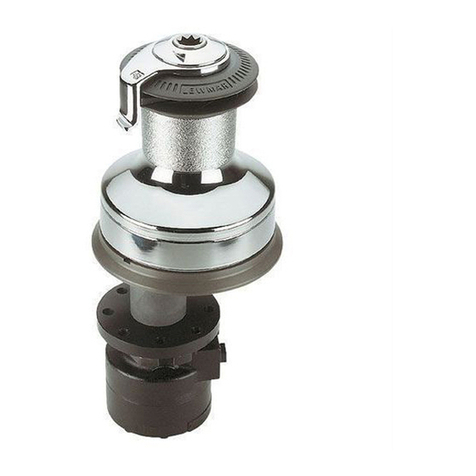
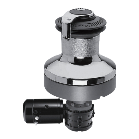
Lewmar C10 Capstan Quick start guide

GB
D
F
E
I
C10 /12 Capstan
Product manual
Owners Installations, Operation & servicing manual
Installations, Betriebs & Wartungshandbuch
Manuel d’installation, de fonctionnement et d’entretien
Manual de instalación, Operación y servicio
Guida all’installazione, all’uso e alla manutenzione

2
IMPORTANT: Read these notes before continuing.
2.1 Capstan general
• Capstan used incorrectly could cause harm to equipment or crew.
• Capstans are powerful equipment and as such should be used with care and treated with respect.
• Boating, like many other activities can be hazardous. Even the correct selection, maintenance and
use of proper equipment cannot eliminate the potential for danger, serious injury or death.
• Keeplimbs,ngers,clothingandhairclearofcapstan.
• Do not use capstans for ANY purpose other than the control of mooring lines
• Neither the capstan nor its deck mounting is designed to withstand anchoring loads generated under
storm conditions.
• Do not wrap chain around a capstan.
• A circuit breaker/isolator should always be used with this capstan to protect the motor and cable
from overheating and damage.
• Electric motors become hot during (and for sometime after) use.
- DO NOT TOUCH THE MOTOR GEARBOX!
• Always switch off this capstan at the circuit breaker/isolator when not in use.
• It is the unavoidable responsibility of the owner or master or other responsible party to assess the risk
of any operation on the vessel.
2.2 Fitting
•Thisequipmentmustbeinstalledandoperatedinaccordancewiththeinstructionscontainedinthis
manual. Failure to do so could result in poor product performance, personal injury and/or damage
to your boat.
•Consulttheboatmanufacturerifyouhaveanydoubtaboutthestrengthorsuitabilityofthe
mounting location.
2.3 Electrical
•Makesureyouhaveswitchedoffthepowerbeforeyoustartinstallingthisproduct.
•Thisproductrequiresinstallationbyasuitablyqualiedelectricalengineer.
WARNING!
2- Safety Notice
1- Introduction
Dear Customer,
Thank you for choosing Lewmar. Lewmar products are world renowned for their quality, technical
innovation and proven performance. With a Lewmar product you will be provided with many years of
outstanding service.
Product support
Lewmar products are supported by a worldwide network of distributors and Authorised Service Repre-
sentatives.Ifyouencounteranydifcultieswiththisproduct,pleasecontactyournationaldistributor,or
your local Lewmar dealer. Details are available at: www.lewmar.com
CE Approvals
ForCEapprovalcerticatescontactLewmar.
Important information about this manual
Throughout this manual, you will see safety and product damage warnings. You must follow these warn-
ings carefully to avoid possible injury or damage.
GB

Lewmar C10/12 Capstan Manual ref B10407 iss.1 | 3
LewmarrecommendsC10/12capstanarespeciedandinstalledby
competent marine engineers.
Plan location carefully:
•Ensure the rope feed correctly.
•Check space available under deck for electric/hydraulic motor unit and cable runs
•With the handle inserted, check that the drum can rotate through 360 degrees.
Max
1.Drill and cut the holes to the size detailed on the template. With a sandwich construction, it is impor-
tant to seal the exposed surfaces.
2.Maximum deck thickness 60mm.
3.Ifthedeckisnotatasuitablemountingpadmayberequiredaboveandbelowdecktotakeup
camber or sheer. Care must be taken to ensure that the top and bottom mounting surfaces are paral-
lel for correct alignment.
WARNING! Extremely heavy,
use mechanical lift aid.
4.Remove the drum cap, washer and drum by undoing the cap with the handle provided.
Select M16 bolts of suitable length (not supplied by Lewmar).
5.Apply a bead of suitable sealant/bedding compound and mount the
capstan through the deck.
Replace the drum and washer and secure them with the drum cap.
6.Under deck, lightly coat the shaft with grease. Ensure the drive key is in place and, selecting the most
suitable positions (electric motor only), slide the motor/ gearbox into position.
Assemble the nuts and washers and secure tightly.
DO NOT use a permanent
adhesive/sealant
123
4 5 6
GB
3- Installation

4
4- Electrical wiring
If you are not sure you understand these guidelines, seek professional help. Ensure that the
installation complies with USCG, ABYC, NMMA or other local regulations.
Lewmar recommends the installer source and install cable that meets the requirements of the
standards and regulations relevant to the installation and codes of practice.
The wiring system should be of the fully insulated type, which avoids possible electrolytic corrosion
problems. We recommend the use of type III stranded, tinned copper wire with copper crimp
terminals. Most modern installations are negative return (negative ground) but polarity should be
checked.
Refer to the wiring diagram and installation instructions provided with the control box to complete the
electrical installation.
Plan the position of the control box near to the capstan, preferably in a dry environment.
The AC motor features an integral electromagnetic brake which is pre-wired to the motor.
If using a 3rd party control using variable speed control, this brake must be powered separately.
Contact Lewmar for advice.
Lewmar D.O.L. Control Boxes
Find a suitable position for the electric safety deck switch(es), remote control and/or rocker switch in
view of the capstan.
Connect up the switch wiring (Follow the mounting instructions supplied with the switch). NOTE: In a
multi station installation all switches must be wired in a parallel circuit.
Check
The capstan operates in the correct direction from all switches.
MODEL VOLTAGE CONTROL BOX CIRCUIT BREAKER*
C10 380/400V AC 68000978 10 A
C10 200/220V AC 68000986 16 A
C12 380/400V AC 68000979 13 A
C12 200/220V AC 68000987 20 A
*Use 3-pole isolator circuit breaker
GB

Lewmar C10/12 Capstan Manual ref B10407 iss.1 | 5
5- Hydraulic system
5.1 Installation
Capstan unit should be connected to a hydraulic powerpack with directional control valve installed
to control the capstan movement.
A typical hydraulic circuit is shown below
5.2 C10/12 Hydraulic motor/gearbox
Thehydraulicmotor/gearboxconsistsofahightorquehydraulicmotorttedtoaninlinegearbox
with brake.
Refertosection5.3forowsandpressuresinformation.
The motor gearbox is self sustaining.
5.6 Motor ports & drain
The Lewmar hydraulic motor ports are:
A & B ports ½” BSP.
Drain port is ¼”BSP.
Note:
•A drain line is required
•The minimum bore diameter of the drain line
required is 10mm (3/8”).
•Safe working pressure: 10 bar.
•Tubing material: Oil compatible semi-rigid
plastic tube braided hose or steel pipe. Hydraulic installation schematic
5.3 Pressures and Flow rates
MODEL NORMAL PRESSURE FLOW RATE
bar psi l/min US gal/min
C10 (200 cc/rev) 175 2573 20–55 5.2–14.3
C12 (250 cc/rev) 13.5:1 G/Box 155 2279 30–80 7.8–20.8
5.4 Hose types
For reliable operation and safety it is essential
to use reinforced braid hose for connecting
to the motor A and B ports which conforms to
SAE100R2A or DIN 20 021 Part 2.
The recommended hose sizes are:
•Upto30l/min+1/2” (13mm) bore diameter.
•Upto50l/min+5/8” (16mm) bore diameter.
•Upto70l/min+3/4” (19mm) bore diameter.
•Upto130l/min+1”(24mm)borediameter.
Ref: 3.78 litres = 1 US gallon
4.54 litres = 1 Imperial gallon
5.5 Recommended Oil
Lewmar recommends Mineral based non-foaming,
anti-wear, water tolerant 32 centistokes at 40°C to
ISO32
GB

6
6- Operation
Warping
Docking or Anchor warp should be laid onto the drum, three turns in a clockwise direction. The
operator should stand in a comfortable position to activate the deck switch whilst tailing the warp
behind and into the storage area, if possible.
Apply Tension
Apply a light even tension to the warp before activating the switch. If very heavy pulls are necessary
apply power in short bursts of about 10 seconds duration. The speed of hauling depends on the
load on the rope.
-+
1.Keeplimbs,ngers,clothingandhairclearofcapstan.
2. Use footswitch to operate the capstan.
3. Do not overload capstan. Avoid stalling capstan.
4. Secure rope to independent strong point, e.g. cleat, to prevent release.
WARNING!
5. When not in use, you must isolate the capstan electrically at the circuit breaker/isolator.
1
2 3 4 5
WARNING!
Should the capstan stall, switch off and wait a few seconds before trying again. If the recommended
breaker/ isolator has tripped, it will require to be manually reset before the capstan can operate
again. It is important to the future, good performance of the capstan’s motor that the capstan is not
allowed to stall for more than a few seconds and therefore, sensible to avoid stalling your capstan
whenever possible.
Power off
Turn the power isolator OFF after use.
GB
GB

Lewmar C10/12 Capstan Manual ref B10407 iss.1 | 7
7- Servicing
Regularly
•Wash down the windlass using fresh water.
•Examine all electrical connections for corrosion, clean and
lightly grease.
•Check mounting bolts and nuts for tightness and condition.
Anually
•Check electric cables for damage. Repair/renew as required.
•Strip the above deck components, clean and lightly grease.
•Inspect condition of motor/gearbox and repaint when neces-
sary
ITEM PART NO DESCRIPTION QTY
1 15044121 Roller bearing 3
2 45002140 Hollow dowel 2
3 65001513 Top nut machining (gyp/drum) 1
4 65001514 Washer, mainshaft 2
5 65001588 Base machining 1
6 65001589 Drum machining 1
7 65001590 Retaining ring 1
8 65001591 Drum ring 1
9 65001592 Mainshaft 1
10 65001593 Sleeve, bearing 1
11 65001594 Adhesive washer 1
12 65001595 Top nut washer 1
13 B0686-A4 Socket HD cap screw 8
14 B0747 Socket HD cap screw 4
15 B1207-A4 M8 washer form B A4 4
16 B12979 Rotary seal 1
17 B8314 O’ring 1
3
12
6
2
8
15
14
16
13
7
17
1
10
9
4
11
5
GB

8
8- Specication
Ø245 mm
(9 5/8 in)
636 mm
(25 1/16 in)
201 mm
(7 7/8 in)
C12 Hydraulic
Ø245 mm
(9 5/8 in)
331 mm
(13 1/16 in)
C10 Hydraulic C10 4kW 400V AC
C10 5.5kW 400V AC
155 mm
(6 1/8 in)
81 mm
(6 1/4 in)
192 mm
(71/2 in)
110 mm
(4 3/8 in)
142 mm
5 5/8
526 mm
(20 3/4 in)
257 mm
(10 1/8 in)
59 mm
(2 5/16 in)
237 mm
(9 5/16 in)
105 mm
(4 1/8 in)
629 mm
(24 3/4 in) 190 mm
(7 1/2 in)
150 mm
(5 7/8 in)
340 mm
(13 3/8 in)
293 mm
(11 9/16 in)
180 mm
(7 1/16 in)
Ø245 mm
(9 5/8 in)
636 mm
(25 1/16 in)
201 mm
(7 7/8 in)
C12 Hydraulic
Ø245 mm
(9 5/8 in)
331 mm
(13 1/16 in)
C10 Hydraulic C10 4kW 400V AC
C10 5.5kW 400V AC
155 mm
(6 1/8 in)
81 mm
(6 1/4 in)
192 mm
(71/2 in)
110 mm
(4 3/8 in)
142 mm
5 5/8
526 mm
(20 3/4 in)
257 mm
(10 1/8 in)
59 mm
(2 5/16 in)
237 mm
(9 5/16 in)
105 mm
(4 1/8 in)
629 mm
(24 3/4 in) 190 mm
(7 1/2 in)
150 mm
(5 7/8 in)
340 mm
(13 3/8 in)
293 mm
(11 9/16 in)
180 mm
(7 1/16 in)
C10 4kW 400V AC C10 Hydraulic
C12 HydraulicC10 5.5kW 400V AC
GB

Lewmar C10/12 Capstan Manual ref B10407 iss.1 | 9
8- Warranty
Lewmar warrants that in normal private pleasure boat
usage and with proper maintenance its products will
conformwiththeirspecicationforaperiodofthree
years from the date of purchase by the end user,
subject to the conditions, limitations and exceptions
listed below. Any product, which proves to be defective
in normal usage during that three-year period, will be
repaired or, at Lewmar’s option, replaced by Lewmar.
A CONDITIONS AND LIMITATIONS
i Lewmar’s liability shall be limited to the repair or
replacement of any parts of the product which are
defective in materials or workmanship.
ii Responsibility for the selection of products
appropriate for the use intended by the Buyer shall
rest solely with the Buyer and Lewmar accepts no
responsibility for any such selection.
iii Lewmar shall not be liable in any way for Product
failure, or any resulting loss or damage that arises
from:
a. use of a product in an application for which it was
not designed or intended;
b. corrosion, ultra violet degradation or wear and tear;
c. a failure to service or maintain the product in
accordance with Lewmar’s recommendations;
d.faultyordecientinstallationoftheproduct(unless
conducted by Lewmar);
e.anymodicationoralterationoftheproduct;
f. conditions that exceed the product’s performance
specicationsorsafeworkingloads.
g. Abuse
iv Product subject to a warranty claim must be returned
to the Lewmar outlet that supplied the product for
examination unless otherwise approved by Lewmar in
writing.
v This warranty does not cover any incidental costs
incurred for the investigation, removal, carriage,
transport or installation of product.
vi Service by anyone other than authorized Lewmar
representatives shall void this warranty unless it
accords with Lewmar guidelines and standards of
workmanship.
vii Lewmar’s products are intended for use only in the
marine environment. Buyers intending to use them
for any other purpose should seek independent
professional advice as to their suitability. Lewmar
accepts no liability arising from such other use.
B EXCEPTIONS
Cover under this Warranty is limited to a period of
one year from the date of purchase by the end user in
the case of any of the following products or parts of
products:
• Electricmotorsandassociatedelectricalequipment
•Electroniccontrols
• Hydraulicpumps,valvesandactuators
•Hatch&Portlightweatherseals
• Productsusedin“GrandPrix”racingapplications
• Productsusedincommercialorcharterapplications
•Anchorrodes
C LIABILITY
i Lewmar’s liability under this warranty shall be to the
exclusion of all other warranties or liabilities (to the
extent permitted by law). In particular (but without
limitation):
a. Lewmar shall not be liable for:
•Anylossofanticipatedturnoverorprotorindirect,
consequential or economic loss;
•Damages,costsorexpensespayabletoanythird
party;
•Anydamagetoyachtsorequipment;
• DeathorpersonalInjury(unlesscausedbyLewmar’s
negligence).
Some states and countries do not allow the exclusion
or limitation of incidental or consequential damages,
so the above limitation or exclusion may not apply to
you
b. Lewmar grants no other warranties regarding the
tnessforpurpose,use,natureorsatisfactoryquality
of the products.
ii Where applicable law does not permit a statutory or
implied warranty to be excluded, then such warranty,
if permitted by that state or country’s law, shall
be limited to a period of one year from the date of
purchase by the end user. Some states and countries
do not allow limitations on how long an implied
warranty lasts, so this limitation may not apply to you.
D PROCEDURE
Notice of a claim for service under this warranty
shall be made promptly and in writing by the end
user to the Lewmar outlet that supplied the product
or to Lewmar Limited at Southmoor Lane, Havant,
Hampshire PO9 1JJ, England.
E SEVERANCE CLAUSE
If any clause of this warranty is held by any court
or other competent authority to be invalid or
unenforceable in whole or in part, the validity of the
remaining clauses of this warranty and the remainder
of the clause in question shall not be affected.
F OTHER RIGHTS
Thiswarrantygivesyouspeciclegalrights,andyou
may also have other legal rights, which vary from
state to state and country to country.
In the case of European States a Consumer customer
(asdenednationally)haslegalrightsunderthe
applicable national law governing the sale of
Consumer Goods; this Warranty does not affect those
rights.
G LAW
This warranty shall be governed by and read in
accordance with the laws of England or the state or
countryinwhichtherstenduserisdomiciledatthe
time of purchase of the product.
H DISPUTES
Any dispute arising under this warranty may, at the
option of the end-user, be referred to alternative
dispute resolution under the rules of the British Marine
Federation or to the Courts of the State whose law
shall govern the warranty or to the Courts of England
and Wales.
The British Marine Federation may be contacted at
Marine House, Thorpe Lea Road, Egham, England,
TW20 8BF
GB
Limited Warranty and Key Terms of Supply by Lewmar

10
WICHTIG! Bitte lesen Sie diese Anleitung vorher sorgfältig durch.
2.1 Ankerwinde, allgemein
•Ankerwinden, die nicht korrekt benutzt werden, können Ausrüstung beschädigen und Personen
verletzen.
•Verholwinden sind leistungsstarke Geräte und sollten mit der nötigen Vorsicht und Respekt benutzt
werden.
•Segeln,wieauchjederandereSportkanngefährlichsein.AuchdiekorrekteAuswahl,Pegeunddie
Nutzung von geeigneter Ausrüstung kann nicht die Möglichkeit einer Verletzung, Gefahr oder sogar
des Ablebens vermeiden.
•Bitte achten Sie darauf, dass sich Hände, Füße, Bekleidung und Haare nicht in der Ankerwinde
verfangen können.
•Lewmar Verholwinden sind ausschließlich zur Kontrolle der Festmacherleinen konstruiert und dürfen
nicht für andere Zwecke verwendet werden.
•Weder die Ankerwinde noch ihre Deckhalterung sind dazu konzipiert, Ankerlasten unter Sturmbedin-
gungen standzuhalten.
•Kette nicht um die Ankerwinde wickeln. Mit dieser Art von Ankerwinde sollte stets ein Sicherung-
sautomat/Trennschalter verwendet werden, um Motor und Kabel vor Überhitzung und Schäden zu
schützen.
•Elektrische Motoren entwickeln beachtliche Wärme während (und für einige Zeit nach) der Nutzung.
MOTOR/GETRIEBE NICHT ANFASSEN!
•Ankerwinde stets am Sicherungsautomaten/ Trennschalter abschalten wenn nicht in Gebrauch.
•Es ist unvermeidbar, dass der Eigner, der Kapitän oder jede andere verantwortliche Person die Ver-
antwortung für jegliches Manöver des Fahrzeuges tragen.
2.2 Montage
•DieseAusrüstungmussgemäßderAnleitungmontiertwerdenundentsprechenddieserAnleitung
auch eingesetzt werden. Ein Nichtbefolgen dieser Regeln kann eine verminderte Produktleistung,
eine Personenverletzung oder eine Beschädigung des Bootes nach sich ziehen.
•Befragen Sie den Hersteller Ihrer Yacht sollten Sie Zweifel an der Festigkeit oder Eignung des
ausgewählten Montageortes haben.
2.3 Elektrik
•BitteunterbrechenSiedieSpannungsversorgungbevorSieanfangen,diesesProduktzu
installieren.
•DereletrischeAnschlusserforderteinenElektrofachmann.
WARNUNG!
2- Sicherheitshinweise
1- Einleitung
Vielen Dank für die Wahl einer Lewmar Ankerwinde. Lewmar Produkte sind weltweit bekannt für ihre
Qualität, technische Innovation und bewiesene Leistungsfähigkeit. Mit einer Lewmar Ankerwinde steht
Ihnen für viele Jahre ein erstklassiger Service zur Verfügung.
Produktunterstützung
Lewmar Produkte werden durch ein weltweites Netz von Großhändlern und autorisierten Service
Stationen betreut. Sollten Probleme mit diesem Produkt auftreten, bitten wir Sie, Ihren nationalen
Großhändler oder Ihren lokalen Lewmar Händler anzusprechen. Details unter: www.lewmar.com
CE Zulassung
FüreinCEZertikatkontaktierenSiebitteLewmar
Wichtige Informationen zu dieser Anleitung
IndieserAnleitungndenSieSicherheitshinweiseundInformationen,umeineBeschädigungdes
Produktes zu vermeiden. Sie müssen diesen Anweisungen strikt folgen, um mögliche Verletzungen
oder Schäden zu vermeiden.
D

Lewmar C10/12 Capstan Manual ref B10407 iss.1 | 11
LewmarempehltdieSpezikationundMontagevonC10/12
Ankerwinden durch kompetente Fachleute.
Wählen Sie den Standort der Ankerwinde sorgfältig aus:
•Achten Sie darauf, dass der Seilvorschub ungehindert erfolgen kann.
•Überprüfen sie den ausreichenden Raum unter Deck für den elektrischen/ hydraulischen Antrieb und
der Kabelsiehe
•Mit eingesetzter Handkurbel in die Deckseinheit überprüfen sie die freie Rotation von 360°
Max
1.Bohren und schneiden Sie die Löcher in den auf der Schablone angegebenen Größen. Bei einer
Verbundbauweiseisteswichtig,dieangeschnittenenOberächenzuversiegeln.
2.Maximale Deckstärke 60mm
3.Wenn das Deck nicht eben ist, eine passende Montageplatte über und unter Deck zu legen, um Wöl-
bungundStrakauszugleichen.DieoberenundunterenMontageächenmüssenunbedingtparallel
liegen, damit die Ausrichtung korrekt ist.
WARNUNG! Extrem schwer,
verwenden sie Hebegeschirr.
4.Entfernen Sie die Kettenrohrabdeckung und den Dichtungsring, indem Sie die Bolzen mit dem mit-
gelieferten Innensechskantschlüssel ausdrehen.
Verwenden Sie M16 Schrauben in geeigneter Länge. (nicht im Liefer-
umfang enthalten)
5.Tragen Sie etwas angemessenen Dichtungsmittel auf oder benutzen Sie den mitgelieferten Dichtung-
sring. Montieren Sie nun die Ankerwinde durch das Deck.
Tauschen Sie jetzt die Trommel und den Dichtungsring aus und sichern Sie ihn gut.
6.Bedecken Sie unter Deck den Schaft mit ein wenig Schmierfett. Stellen Sie sicher, dass der
Fahrtschlüssel an der richtigen Stelle ist und schieben Sie den Motor/das Getriebe in Position, indem
Sie die beste der 8 Positionen wählen.
Montieren Sie die Muttern und Dichtungen und sichern Sie diese gut.
Benutzen Sie keinesfalls
Permanentdichtmasse
123
4 5 6
D
3- Montage

12
4- Elektrische Montage
Sind Sie sich nicht sicher diese Anleitung verstanden zu haben suchen Sie bitte professionelle
Unterstützung. Stellen Sie sicher dass die Installation den Anforderungen von USCG, ABYC, NMMA
oder nationalen Bestimmungen entspricht.
LewmarempehltdasderMonteurdenStandardsundRegelnfürdieInstallationfolgeleistet.
Der Bediener sollte die Ankerwinde in Blickkontakt haben. Die Verkabelung sollte mit entsprechenden
voll isolierten Kabeln des empfohlenen Querschnittes erfolgen, um Kurzschlüsse und Elektrolyse zu
vermeiden. Bitte informieren sie sich über die am besten geeigneten Kabel. Die meisten modernen
Installationen haben minus als Erdung, aber die Polarität sollte immer vor Ort geprüft werden.
Einzelheiten für die Verkabelung und Anschluss der elektrischen Leitungen entnehmen Sie bitte den
beiliegenden Zeichnungen.
Plan the position of the control box near to the capstan, preferably in a dry environment.
Der AC-Motor verfügt über eine integriete, elektromagnetische Bremse, die mit dem Motor vorver-
drahtet ist. Bei Gebrauch einer dritten Steuerung mit variabler Drehzahlreglung , muß die Bremse
separat mit Strom versorgt werden. Kontaktieren Sie Lewmar für weite Auskünfte
Lewmar D.O.L. Control Boxes
Finden Sie eine geeignete Stelle für den/die elektrischen Sicherheitsdeckschalter, die Fernsteuerung
und/oder den Kippschalter; diese Stelle sollte in Sicht der Winde liegen.
Verbinden Sie die entsprechende Schalterverdrahtung. Folgend Sie der Installationsanleitung die dem
Schalter beiliegt. Sollten mehrere Schalter installiert werden müssen diese parallel angeschlossen
werden.
Überprüfen Sie
daß die Winde von allen Schaltern aus in die richtige Richtung läuft.
MODEL VOLTAGE CONTROL BOX CIRCUIT BREAKER*
C10 380/400V AC 68000978 10 A
C10 200/220V AC 68000986 16 A
C12 380/400V AC 68000979 13 A
C12 200/220V AC 68000987 20 A
*Verwenden Sie 3 polige Sicherungsautomaten
D

Lewmar C10/12 Capstan Manual ref B10407 iss.1 | 13
5- Hydraulisches System
5.1 Installation
Die Ankerwinde sollte an die Hydraulikversorgung mit einem Regelventil angeschlossen werden
um die Bewegung der Winde zu kontrollieren.
EinetypischeHydraulikinstallationndensienachfolgend.
5.2 C10/12 Hydraulische Motor/Getriebeeinheit
Die hydraulische Motor/Getriebeeinheit besteht aus einem Hochleistungs Motor, der auf ein Inline-
Getriebe mit Bremse montiert ist.
FlußratenundDruckinformationenndensieinSektion5.3.
Die Antriebseinheiten sind selbstblockierend.
5.6 Motor Anschlußports & Drainage
Die Lewmar Hydraulikmotor Ports sind:
A & B Port sind ½” BSP.
Drainage Port ist ¼”BSP.
Note:
•Eine Drainageleitung ist notwendig
•Der innere Mindestdurchmesser der Drain Line
beträgt 10mm (3/8”).
•Sicherer Arbeitsdruck: 10 Bar.
•Leitungsmaterial: Öl resistentes semi-rigid
unststoffschlauch mit Gewebehülle oder Stahl-
Rohr. Schema Hydraulikinstallation
5.3 Druck und Durchussmengen
MODEL NORMAL PRESSURE FLOW RATE
bar psi l/min US gal/min
C10 (200 cc/rev) 175 2573 20–55 5.2–14.3
C12 (250 cc/rev) 13.5:1 G/Box 155 2279 30–80 7.8–20.8
5.4 Schlauch Typen
Für eine reibungslose Bedienung und Sicherheit
ist es erforderlich verstärkt ummantelte Schläuche
zu verwenden die mit Motor A and B Anschlüssen
verbunden werden. Sie sollten mit SAE100R2A oder
DIN 20 021 Part 2 übereinstimmen.
Die erforderlichen Schlauch Größen sind:
•Über30l/min+1/2” (13mm) Schlauchdurchmesser
•Über50l/min+5/8” (16mm) Schlauchdurchmesser
•Über70l/min+3/4” (19mm) Schlauchdurchmesser
•Über130l/min+1”(24mm)Schlauchdurchmesser
Ref: 3.78 litres = 1 US gallon
4.54 litres = 1 Imperial gallon
5.5 Empfohlenes Öl
Lewmarempehltmineralisches,nicht
schäumendes, anti-Verschleiß, Wasser tolerant 32
centistokes bei 40 Grad Celsius ISO 32
D

14
6- Bedienung
Verholen
Anlege- oder Ankertrossen auf die Trommel wickeln, und zwar drei Umdrehungen im Uhrzeigersinn. Der
Bediener sollte dabei so stehen, dass er den Deckschalter aktivieren kann, und die Warptrosse dabei
nach Möglichkeit gleichzeitig in die Lagerposition gebracht wird.
Leichtes Anspannen
Warptrosse leicht und gleichmäßig anspannen, bevor der Schalter betätigt wird. Ist ein sehr starkes
Anziehen erforderlich, so ist in kurzen Schüben von rund 10 Sekunden Dauer vorzugehen. Die Einhol-
geschwindigkeit hängt dabei von der Belastung des Seils ab.
-+
1. Bitte achten Sie darauf, dass sich Hände, Füße, Bekleidung und Haare nicht in der Ankerwinde verfangen können.
2. Betätigen Sie den Fußschalter zum Betrieb der Ankerwinde.
3. Ankerwinde nicht überlasten. Festfahren der Ankerwinde oder plötzliches Anhalten des Motors vermeiden
4. Seil an einem unabhängigen Festpunkt, z.B. Poller, xieren, um ein unbeabsichtigtes Lösen zu vermeiden.
WARNUNG!
5. Wenn nicht in Gebrauch muss die Winde mit dem Sicherungsautomat/Trennschalter isoliert werden.
1
2 3 4 5
WARNUNG!
Sollte sich die Ankerwinde festfahren, Gerät abschalten und nach ein paar Sekunden einen erneuten
Versuch vornehmen. Wurde der empfohlene Sicherungsautomat/Trennschalter ausgelöst, so ist eine
Rückstellung von Hand erforderlich, bevor die Ankerwinde wieder betriebsbereit ist. Für die weitere
fehlerfreie Funktion des Ankerwindenmotors ist es von größter Wichtigkeit, dass die
Ankerwinde nicht länger als ein paar Sekunden in festgefahrener Position verharrt, und aus diesem
Grunde sollte ein Festfahren der Ankerwinde nach Möglichkeit stets vermieden werden.
Netzabschaltung
Netztrennschalter nach Gebrauch stets in die Aus-Stellung (OFF) bringen.
D

Lewmar C10/12 Capstan Manual ref B10407 iss.1 | 15
7- Zeitplan
Regelmäßig
•Die Ankerwinde mit Frischwasser spülen.
•Überprüfung aller elektrischen Verbindung auf Rost, reinigen
und leicht einfetten.
•Überprüfen Sie die Montagebolzen und Muttern.
Jährlich
•Überprüfung aller elektrischen Verbindungen auf Beschädi-
gungen, instandsetzen oder erneuern falls erforderlich.
•Demontieren der Desckseinheit, reinigen und leicht einfetten.
•Überprüfen der Antriebseinheit auf Korrosion. Reinigen
und Anstrich nachbessern mit Marine Grade Öl basierter
Lackfarbe
ITEM PART NO DESCRIPTION QTY
1 15044121 Roller bearing 3
2 45002140 Hollow dowel 2
3 65001513 Top nut machining (gyp/drum) 1
4 65001514 Washer, mainshaft 2
5 65001588 Base machining 1
6 65001589 Drum machining 1
7 65001590 Retaining ring 1
8 65001591 Drum ring 1
9 65001592 Mainshaft 1
10 65001593 Sleeve, bearing 1
11 65001594 Adhesive washer 1
12 65001595 Top nut washer 1
13 B0686-A4 Socket HD cap screw 8
14 B0747 Socket HD cap screw 4
15 B1207-A4 M8 washer form B A4 4
16 B12979 Rotary seal 1
17 B8314 O’ring 1
3
12
6
2
8
15
14
16
13
7
17
1
10
9
4
11
5
D

16
8- Specication
Ø245 mm
(9 5/8 in)
636 mm
(25 1/16 in)
201 mm
(7 7/8 in)
C12 Hydraulic
Ø245 mm
(9 5/8 in)
331 mm
(13 1/16 in)
C10 Hydraulic C10 4kW 400V AC
C10 5.5kW 400V AC
155 mm
(6 1/8 in)
81 mm
(6 1/4 in)
192 mm
(71/2 in)
110 mm
(4 3/8 in)
142 mm
5 5/8
526 mm
(20 3/4 in)
257 mm
(10 1/8 in)
59 mm
(2 5/16 in)
237 mm
(9 5/16 in)
105 mm
(4 1/8 in)
629 mm
(24 3/4 in) 190 mm
(7 1/2 in)
150 mm
(5 7/8 in)
340 mm
(13 3/8 in)
293 mm
(11 9/16 in)
180 mm
(7 1/16 in)
Ø245 mm
(9 5/8 in)
636 mm
(25 1/16 in)
201 mm
(7 7/8 in)
C12 Hydraulic
Ø245 mm
(9 5/8 in)
331 mm
(13 1/16 in)
C10 Hydraulic C10 4kW 400V AC
C10 5.5kW 400V AC
155 mm
(6 1/8 in)
81 mm
(6 1/4 in)
192 mm
(71/2 in)
110 mm
(4 3/8 in)
142 mm
5 5/8
526 mm
(20 3/4 in)
257 mm
(10 1/8 in)
59 mm
(2 5/16 in)
237 mm
(9 5/16 in)
105 mm
(4 1/8 in)
629 mm
(24 3/4 in) 190 mm
(7 1/2 in)
150 mm
(5 7/8 in)
340 mm
(13 3/8 in)
293 mm
(11 9/16 in)
180 mm
(7 1/16 in)
Ø245 mm
(9 5/8 in)
636 mm
(25 1/16 in)
201 mm
(7 7/8 in)
C12 Hydraulic
Ø245 mm
(9 5/8 in)
331 mm
(13 1/16 in)
C10 Hydraulic C10 4kW 400V AC
C10 5.5kW 400V AC
155 mm
(6 1/8 in)
81 mm
(6 1/4 in)
192 mm
(71/2 in)
110 mm
(4 3/8 in)
142 mm
5 5/8
526 mm
(20 3/4 in)
257 mm
(10 1/8 in)
59 mm
(2 5/16 in)
237 mm
(9 5/16 in)
105 mm
(4 1/8 in)
629 mm
(24 3/4 in) 190 mm
(7 1/2 in)
150 mm
(5 7/8 in)
340 mm
(13 3/8 in)
293 mm
(11 9/16 in)
180 mm
(7 1/16 in)
Ø245 mm
(9 5/8 in)
636 mm
(25 1/16 in)
201 mm
(7 7/8 in)
C12 Hydraulic
Ø245 mm
(9 5/8 in)
331 mm
(13 1/16 in)
C10 Hydraulic C10 4kW 400V AC
C10 5.5kW 400V AC
155 mm
(6 1/8 in)
81 mm
(6 1/4 in)
192 mm
(71/2 in)
110 mm
(4 3/8 in)
142 mm
5 5/8
526 mm
(20 3/4 in)
257 mm
(10 1/8 in)
59 mm
(2 5/16 in)
237 mm
(9 5/16 in)
105 mm
(4 1/8 in)
629 mm
(24 3/4 in) 190 mm
(7 1/2 in)
150 mm
(5 7/8 in)
340 mm
(13 3/8 in)
293 mm
(11 9/16 in)
180 mm
(7 1/16 in)
Ø245 mm
(9 5/8 in)
636 mm
(25 1/16 in)
201 mm
(7 7/8 in)
C12 Hydraulic
Ø245 mm
(9 5/8 in)
331 mm
(13 1/16 in)
C10 Hydraulic C10 4kW 400V AC
C10 5.5kW 400V AC
155 mm
(6 1/8 in)
81 mm
(6 1/4 in)
192 mm
(71/2 in)
110 mm
(4 3/8 in)
142 mm
5 5/8
526 mm
(20 3/4 in)
257 mm
(10 1/8 in)
59 mm
(2 5/16 in)
237 mm
(9 5/16 in)
105 mm
(4 1/8 in)
629 mm
(24 3/4 in) 190 mm
(7 1/2 in)
150 mm
(5 7/8 in)
340 mm
(13 3/8 in)
293 mm
(11 9/16 in)
180 mm
(7 1/16 in)
C10 4kW 400V AC C10 Hydraulic
C12 HydraulicC10 5.5kW 400V AC
D

Lewmar C10/12 Capstan Manual ref B10407 iss.1 | 17
8- GEWÄHRLEISTUNG
Lewmar garantiert für einen Zeitraum von drei Jahren
ab Kaufdatum – den normalen Gebrauch der Produkte
vorausgesetzt -, dass seine Produkte keine Herstellungs-
oder Materialfehler aufweisen. Diese Gewährleistung
erfolgt zu den Bedingungen und mit den Beschränkungen
und Ausnahmen, die nachstehend aufgeführt sind.
Teile, die sich bei normalem Gebrauch während der
dreijährigen Garantiezeit als fehlerhaft erweisen,
werden von Lewmar repariert oder aufgrund Lewmars
Entscheidung ausgetauscht.
A BEDINGUNGEN UND EINSCHRÄNKUNGEN
i Die Haftung von Lewmar ist auf die Reparatur oder
den Austausch der Teile beschränkt, die Material- oder
Herstellungsfehler aufweisen.
ii Die Feststellung, ob das Material für die vom Käufer
bezweckte Verwendungsart geeignet ist, fällt unter
die alleinige Verantwortung des Käufers. Lewmar
übernimmt keine Haftung im Zusammenhang mit einer
solchen Eignungsfeststellung.
iii Lewmar kann nicht haftbar gemacht werden für:
a. Versagen, Verlust oder Schäden aufgrund der
Nutzung der Produkte in Anwendungen, für die sie
nicht bestimmt sind.
b. Versagen, Verlust oder Schäden durch Korrosion,
UVZersetzung oder normalen Verschleiß.
c. Versagen, Verlust oder Schäden durch Wartung,
die nicht gemäß den Empfehlungen von Lewmar
vorgenommen wird.
d. Versagen, Verlust oder Schäden durch fehlerhafte
oder falsche Installation des Produkts (sofern nicht
durch Lewmar durchgeführt).
e. Versagen, Verlust oder Schäden durch Änderungen
jeglicher Art des Produkts.
f. Versagen, Verlust oder Schäden durch
Überbeanspruchung der Produkte.
g. Mißbrauch
iv Produkte, für die Garantieansprüche geltend gemacht
werden, müssen an die Lewmar- Niederlassung,
die das Produkt geliefert hat, zwecks Prüfung
zurückgesandt werden, es sei denn, dass Lewmar
schriftlich eine andere Vereinbarung bestätigt hat.
v Lewmar übernimmt keine Frachtkosten oder Kosten für
Installationsarbeiten (Ein- und Ausbau) sowie Kosten
für die Untersuchung in Zusammenhang mit einem
Garantieanspruch.
vi Diese Garantie verfällt, wenn andere Personen als
zugelassene Lewmar-Vertreter Servicearbeiten
in Bezug auf die Produkte durchführen, es sei
denn, dass diese Arbeiten den Richtlinien und
Herstellungsstandards von Lewmar entsprechen.
vii Lewmar Produkte sind ausschließlich für den Einsatz
im Wassersport-Bereich konzipiert. Käufer, die diese
Produkte für jeglichen anderen Zweck benutzen ollen,
sollten sich hinsichtlich einer solchen Eignung an einen
unabhängigen Sachverständigen wenden. Lewmar
unterliegt dabei keiner Haftung durch den Gebrauch,
den Lewmar nicht ausdrücklich gebilligt hat.
B AUSNAHMEN
Die Garantie ist in folgenden Fällen auf die Dauer eines
Jahres ab Kaufdatum befristet:
• ElektrischeMotorenundelektrischeAusrüstung
•ElektronischeSteuerungen
• HydraulischePumpen,VentileundDrehzahlregler
•Wetterdichtungen
• Produkteim„GrandPrix”-Einsatz
• ProdukteimProfesionellenoderCharterEinsatz.
•Ankerleine
C HAFTUNG
i Die Haftung seitens Lewmar schließt alle anderen
Garantien und Verantwortlichkeiten (im gesetzlich
zulässigen Rahmen) aus.
Insbesondere (jedoch ohne Einschränkung):
a. haftet Lewmar nicht für:
•entgangenenerwartetenUmsatzoderGewinnoder
indirekte Schäden, Folgeschäden oder wirtschaftliche Schäden.
•Schäden, Kosten oder Aufwendungen, die an Dritte zahlbar sind.
•SchädenanYachtenoderAusrüstung.
• TododerPersonenschäden(ausgenommenverursacht
durch Fahrlässigkeit von Lewmar). Einige Staaten
und Länder gestatten keinen Ausschluss oder keine
Beschränkung des Schadenersatzes für Aufwendungen
bei Vertragserfüllung oder Folgeschäden. In diesen
Fällen gelten die oben genannten Einschränkungen
oder Ausschlussbedingungen möglicherweise nicht.
b. Lewmar gewährt keine Garantie bezüglich der
Eignung der Produkte hinsichtlich der vom Käufer
bezweckten Nutzung, des Gebrauchs, der Art oder der
befriedigenden Qualität der Produkte.
ii Wenn die geltenden Gesetze des betreffenden Landes
den Ausschluss von Garantien nicht erlauben, wird
die Garantie, falls die Gesetze dies zulassen, auf
ein (1) Jahr ab dem Kaufdatum beschränkt. Einige
Staaten und Länder gestatten keine Beschränkung der
gesetzlichen Gewährleistung. In diesen Fällen gelten
diese Einschränkungen möglicherweise nicht.
D VORGEHENSWEISE
Die Geltendmachung von Gewährleistungsansprüchen
im Rahmen dieser Garantie ist vom Endabnehmer
unverzüglich und in schriftlicher Form gegenüber der
Lewmar- Niederlassung, die das Produkt geliefert hat,
oder Lewmar Limited in Southmoor Lane, Havant,
Hampshire, PO9 1JJ, Großbritannien, anzuzeigen.
E ABTRENNBARKEIT EINZELNER BESTIMMUNGEN
Falls eine oder mehrere dieser Garantiebestimmungen
von einer zuständigen Behörde ganz oder teilweise
für nicht gültig oder nicht einklagbar erachtet
werden, mindert dies nicht die Gültigkeit der übrigen
Bestimmungen dieser Garantie und des Rests der
betreffenden Bestimmung.
F SONSTIGE RECHTE
Aufgrund dieser Garantie haben Sie bestimmte
gesetzliche Rechte. Darüber hinaus stehen Ihnen
gegebenenfalls je nach Land verschiedene sonstige
gesetzliche Rechte zu. Bei Endverbrauchern aus den
Mitgliedsstaaten der Europäischen Union (gemäß der
rechtlichenDenitiondesjeweiligenLandes)geltendie
Rechte aus den entsprechenden nationalen Gesetzen,
die den Verkauf von Konsumgütern regeln. Diese Rechte
werden durch diese Garantie in keener Weise eingeschränkt.
G GERICHTSSTAND
Für diese Garantie ist englisches Recht oder das Recht
desjenigen Landes maßgeblich, in dem der erste
Endkunde seinen Wohnsitz zum Zeitpunkt des Kaufes
dieses Produkts hatte.
H STREITFALL
Streitfälle, die sich im Rahmen dieser Garantie
ergeben, können nach Wahl des Endabnehmers an
ein alternatives Verfahren zur Streitklärung gemäß den
Bestimmungen der British Marine Federation oder an
ein Gericht desjenigen Landes, dessen Gesetze für
dieseGewährleistungAnwendungnden,oderanein
Gericht in England oder Wales überwiesen werden. Die
Anschrift der British Marine Federation lautet: Marine
House, Thorpe Lea Road, Egham, TW20 8BF, Großbritannien.
D
GEWÄHRLEISTUNG und LIEFERBEDINGUNGEN VON LEWMAR

18
IMPORTANT: Veuillez lire ce qui suit avant de poursuivre.
2.1 Généralités
•Les cabestans utilisés incorrectement peuvent entraîner des dommages corporels ou matériels.
•Les cabestants sont des appareils puissant et doivent être donc utilisés avec attention et respect.
•La navigation, comme de nombreux autres sports peut être dangereuse. Le choix d’un matériel
adapté, son bon entretien et son utilisation dans les règles de l’art n’élimine pas le danger potentiel
de blessure grave ou mortelle.
•Veillez à ne pas approcher bras, jambes, doigts, vêtements ou cheveux du cabestan.
•Ne pas utiliser le cabestan pour toute autre application que le controle des amarres.
•Ni le cabestan ni son montage sur le pont ne sont conçus pour supporter des poids d’ancrage par
gros temps.
•N’enroulez pas de chaîne autour d’un cabestan.
•Un disjoncteur doit toujours être employé avec ce cabestan pour empêcher le moteur et les câbles
de surchauffer et d’être endommagés.
•Un moteur électrique dégage de la chaleur pendant et aprés son utilisation, NE PAS TOUCHER
L’ENSEMBLE MOTEUR/ MOTORÉDUCTEUR.
•Eteignez toujours le cabestan au disjoncteur lorsqu’il n’est pas utilisé.
•Le propriétaire, chef de bord ou autre est seul responsable de juger des risques des manoeuvres à
bord.
2.2 Installation
•Cetéquipementdoitêtreinstalléetutiliséselonlesinstructionscontenuesdanscemanuel.Lenon-
respect de ces instructions peut entraîner un mauvais fonctionnement de l’appareil, des dommages
aux personnes et/ou au bateau.
•Veuillezconsulterlefabricantdubateausivousdoutezdelasoliditéoudelapertinancede
l’emplacement de montage.
2.3 Electrique
•Assurez-vousd’avoircoupél’alimentationélectriqueavantdecommencerl’installation.
•Ceproduitdoitetreinstalléparunélectriciendûmentqualié.
ATTENTION!
2- Avis de sécurité
1- Introduction
Cher Client,
Merci d’avoir choisi un guindeau Lewmar. Les produits Lewmar sont reconnus dans le monde entier
pour leurs qualités, innovations techniques et leurs performances. Vous êtes assuré de nombreuses
années de service exceptionnel.
Soutien Technique
Les produits Lewmar sont suivis par un réseau mondial de distributeurs et de sociétés de services
agrées.Sivousrencontrezdesdifcultésavecceproduit,veuillezcontactervotredistributeurnational
ou votre agent local. Détails disponibles sur:: www.lewmar.com
Agrément CE
PourobtenirlescerticatsCEveuillezcontacterLewmar.
Informations importantes à propos de ce manuel
Dans ce manuel vous allez voir des mises en garde de sécurité et des précautions d’emplois. Vous
devezsuivreattentivementcesinstructionsand’éviterdepossiblesaccidentsoudommages.
F

Lewmar C10/12 Capstan Manual ref B10407 iss.1 | 19
LewmarrecommandequelecabestanC10/12soitspéciéetinstallé
parunepersonnequaliédanslemilieudelamarine.
Planierl’emplacementsoigneusement:
•Assurez-vous que la corde puisse bien ciculer
•Vérierl’espacedisponiblesouslepontpourlemotoréducteurélectriqueouhydrauliqueetles
câbles
•Aveclamanivelleinséré,vérierquelapoupéepuissetournerde360degrés.
Max
1.Percez et découpez les trous à la dimension indiquée sur le modèle. En cas de construction en sand-
wich, il est important de rendre étanches les surfaces exposées.
2.Epaisseur de pont maximum 60mm.
3.Si le pont n’est pas plat, il peut être nécessaire de prévoir une semelle au-dessus et au-dessous du
pontpourcompenserlecambrage.Assurez-vousquelessurfacesdexationsupérieureetinférieure
sont paralléles et qu’elles permettent une bonne mise en ligne.
ATTENTION! Extrêmement
lourd, utiliser une aide de
levage mécanique.
4.Retirez le couvercle d’écubier, la rondelle et le barbotin en desserrant le couvercle avec la manivelle
fournie.
Selectionnez des vis M16 de longueur approprié (Non fourni par
Lewmar).
5.Appliquez une perle d’enduit étanche ou utilisez le joint fourni et
montez le cabestan à travers le pont
Replacezlebarbotinetlarondelle,etxezlesaveclecouvercled’écubier.
6.Souslepont,graissezlégèrementl’axe.Vériezquelaclavetted’entraînementestenplaceet,en
sélectionnant la plus adaptée des 8 positions, faîtes coulisser le moteur/transmission en place. As-
semblez les écrous et les rondelles et serrez fermement.
NE PAS utiliser un adhésif
permanent
123
4 5 6
F
3- Installation

20
4- Installation Electrique
Si vous n’êtes pas certain d’avoir compris ces informations demandez l’aide d’un professionnel.
S’assurer que l’installation soit conforme USCG, ABYC, NMMA ou autres régulations.
Lewmar recommande que l’installateur source et installe des câbles répondant aux exigences des
normes et des règlements pertinents à l’installation et des codes de pratique.
Lecâblageélectriquedoitêtrefaitavecdescâblesisolésandeminimiserlesproblèmes
d’électrolyse. Nous recommandons l’utilisation de câble en cuivre type III étamés pour recevoir
des cosses en cuivre. La plupart des installations modernes ont un retour négatif (terre négative),
cependant la polarité doit être contrôlée.
Voir le schéma électrique et les instructions fournis avec la boite de control pour compléter l’installation
électrique.
Positionner la boite de control près du cabestan, de préférence dans un endroit sec.
Le moteur AC comprend un frein électromagnétique qui est pré-câblé au moteur.
Si vous utilisez un autre type de contrôle utilisant un variateur de vitesse, ce frein doit être alimenté
séparément. Contactez Lewmar pour tout renseignement.
Controleurs Lewmar D.O.L.
Trouvez un emplacement convenable pour l’(les) interrupteur(s) de pont, la télécommande et/ou la
commande de timonerie en vue du cabestan.
Raccordez les câbles à l’interrupteur. Suivre la notice d’installation de l’interrupteur. NOTE: si plusieurs
interrupteurs sont installés ceux-ci doivent être montés en parallèle.
Vériez
Que le cabestan fonctionne dans la bonne direction à partir de tous les interrupteurs.
MODEL VOLTAGE CONTROL BOX CIRCUIT BREAKER*
C10 380/400V AC 68000978 10 A
C10 200/220V AC 68000986 16 A
C12 380/400V AC 68000979 13 A
C12 200/220V AC 68000987 20 A
*Utilisez un isolateur/coupe circuit 3-pole
GB
FF
This manual suits for next models
1
Table of contents
Languages:
Other Lewmar Winch manuals