Lewmar OCEAN Series Quick start guide

Lewmar OCEAN & EVO®
Electric/Hydraulic Winches
B2303 Issue 14
Ocean Winch size 40-111 Evo™ Winch size 40-90
Owners Installations, Operation & servicing manual
GB

2
GB
1. Introduction
Dear Customer,
Thank you for choosing Lewmar. Lewmar products are world renowned for their quality, technical innovation and
proven performance. With a Lewmar product you will be provided with many years of outstanding service.
Product support
Lewmar products are supported by a worldwide network of distributors and Authorised Service Representatives.
If you encounter any difficulties with this product, please contact your national distributor, or your local Lewmar
dealer. Details are available at www.lewmar.com
CE Approvals
For CE approval certificates contact Lewmar.
Important information about this manual
Throughout this manual, you will see safety and product damage warnings. You must follow these warnings
carefully to avoid possible injury or damage.
The type of warnings, what they look like, and how they are used in this manual are explained as follows:.
WARNING!
This is a warning against anything which may
cause injury to people if the warning is ignored.
You are informed about what you must or must
not do in order to reduce the risk of injury to
yourself and others.
SAFETY SYMBOL
When you see the safety symbol it
means: “Do not...”; “Do not do this”; or
“Do not let this happen”.

Lewmar OCEAN & EVO® Electric/Hydraulic Winches ref B2303 Iss.14 | 3
2. Safety Notice
IMPORTANT: Read these notes before continuing.
2.1 Winches general
Please ensure that you thoroughly understand the operation and safety requirements of the winch before com-
mencing the installation. Only persons who are completely familiar with the controls and those who have been
fully made aware of the correct use of the winch should be allowed to use it. If there is any doubt of how to
install or operate this unit please seek advice from a suitably qualified engineer.
• Winches used incorrectly could cause harm to equipment or crew.
• Winches should be used with care and treated with respect.
• Sailing, like many other sports can be hazardous. Even the correct selection, maintenance and use of
proper equipment cannot eliminate the potential for danger, serious injury or death.
• Lewmar winches are designed and supplied for line control in marine applications and are to be used in
conjunction with appropriate clutches, cleats and other manual controls and stoppers.
• It is the unavoidable responsibility of the owner or master or other responsible party to assess the risk of
any operation on the vessel.
• Under no circumstances should any self tailing winch be used in self tailing mode for any liing operation;
rather suitable and adequate manual tailing should be arranged with proper means of manually cleating or
stopping the hoist.
• Every winch should be installed with adequate means of manually cleating or stopping the loaded ropes.
2.2 Fitting
• This equipment must be installed and operated in accordance with the instructions contained in this
manual. Failure to do so could result in poor product performance, personal injury and/or damage to your
boat.
• Consult the boat manufacturer if you have any doubt about the strength or suitability of the mounting
location.
2.3 Electrical
• Make sure you have switched off the power before you start installing this product.
• If in doubt about installing electrical equipment please seek advice from a suitably qualified electrical
engineer.
WARNING!

4
OCEAN KIT
40 48040055
46 48046055
48 48048055
50 48050055
54 48054055
58 48058055
65 48065055
A B
C
EVO® KIT
40 48540055
45 48545055
50 48550055
55 48555055
65 48565055
A B
C
360˚
-5° to -10°
-5° to -10°
3.3-2
3.3-1
GB
3. Installation
3.2 Preparing manual winch for electric conversion
IMPORTANT: Check existing winch location is suitable for positioning motor/gearbox, see section 3.4.
• Remove the winch from the deck, replace centre stem with supplied kit centre stem. Reassemble winch, fix
power drive base to the centre stem and fit motor/gearbox as instructed in this manual.
3.3 Above deck preparation electric/hydraulic winch
IMPORTANT: Always keep in mind the space available below deck for the motor/gearbox or hydraulic drive unit.
Plan location carefully before drilling any holes and allow for the following:
1. 360 degree rotation of manual operating handle.
2. Lewmar recommend that the rope enters onto the drum at an angle of –5° to –10° to the base axis of the
winch. To achieve this angle it may be necessary to use a base wedge when installing the winch.
3.1 Electric conversion kit
1. Ocean Wavespring manual winches manufactured from 1992 and EVO® manual winches can be converted
to electric powered operation with a Lewmar conversion kit consisting of the following:
• Centre stem (A) and a power drive base (B).
• Then specify a suitable Lewmar motor/gearbox (C) to form the basic electric winch deck unit conversion.

Lewmar OCEAN & EVO® Electric/Hydraulic Winches ref B2303 Iss.14 | 5
3.3-3
B
C
A
3.3-4 3.3-5
3.4-1 3.4-2
3. It is essential that the winch is fixed to an even surface for maximum performance.
4. If practical, for best performance, the winch should be installed so that the output gear (A) is situated in
the optimum position in relation to the load (B) and sheet line entry (C).
5.
Winches 40-65
Once position of winch is established, mark position of centre stem and drill Ø64mm hole. Strip winch (section
3.5) place base plate on deck then mark through mounting bolt holes, remove and drill to size of bolts.
Winches 68-111
Remove the winch drum. Access to mounting holes is available through holes in the base of the centre stem.
Mark hole positions and drill as necessary.
3.4 Below deck preparation
IMPORTANT: The positioning of the motor/gearbox or hydraulic drive unit must be checked prior to cutting for
deck/hull and bulkhead clearance.
1. The motor/gearbox can be rotated in 90 degree steps.
2. The motor rotation is factory set for fitting to drive sha as shown.

6
OCEAN EVO™
1st 2nd 3rd
68-111 70-90
3.4-43.4-3
GB
3. If the motor/gearbox is fitted the opposite way round it will produce the following problems:
• On a single speed winch it will not operate and make a clicking noise. Remove motor/gearbox and refit the
opposite way round.
• On a 2 or 3 speed winch it will dramatically reduce performance. Contact Lewmar for correct fitting of
electrical connections to rectify this situation or refit the motor/gearbox the opposite way round.
4. Correct spindle rotation when fitted and operated.
• Check clearance below deck and accessibility then position the deck switches near and in view of the
winch. Use template as a guide to cut/drill hole, fit switch and seal.
• Once you have selected the ideal position for winch, motor/gearbox and controls, double check everything
and only then drill holes in the deck.
NOTE: Illustrations based on Model 50 Ocean winch unless stated otherwise. For winch models over 65 just
removing the drum gives access to fixing bolt holes.
• Place the winch in position to ensure correct fit once the holes have been drilled/cut.
1. Unscrew the top cap anti-clockwise and remove.
2. OCEAN 40- Remove feeder arm and collets.
OCEAN 46-111- Remove feeder arm.
3. EVO®- Rotate the drum until the cutout in the upper crown is opposite the collets.
3.5 Fitting an electric/hydraulic winch 40-65
WARNING! Isolate the winch
using circuit breaker/isolator.

Lewmar OCEAN & EVO® Electric/Hydraulic Winches ref B2303 Iss.14 | 7
3.7-2
3.5-2
3.5 -1 3.5-3
OCEANEVO® EVO®
3.5-53.5-4
4. .Li off drum. Remember to take care in re-fitting the drum washer with bevel on underside.
5. Remove all screws holding centre stem to base. Using a flat bladed screwdriver in the drainage slots, lever
off centre stem assembly clear of the two dowel pins.
NOTE: For manual to electric winch conversion, replace centre stem with kit supplied unit.

8
3.5-6
OCEAN
40~65
EVO®
40~65
3.5-7
3.5-8 3.5-9
GB
6. Take care to hold the gear stack in position as shown. Keep pawls and pawl springs in place while rebuilding/
placing the centre stem onto the base.
NOTE: If pawl gear falls away, ensure shoulder face is down on re-assembly. Take notes of gear and other com-
ponent positions if replacing the original stem with the conversion kit stem ready for reassembly.
7. Remove the base plate cover. Li the base and bed down with a light
coating of sealing compound to prevent leaks.
• Avoid using excessive sealant.
8. Consult the fastening guide for bolt type and length. Bolt the base plate to the deck ensuring that all fasten-
ing heads are countersunk then replace base plate cover.
NOTE: If using silicone or other rubbery type sealant, it is advisable to allow curing of the sealant before final
tightening of the mounting nuts.
9. Refit the centre stem assembly, taking care to hold the gear stack in position as before. Rotating the gears
will facilitate re-engagement of the pawls and ratchet tracks.
• Replace the drum, collets and feeder arm in correct position and screw on the top cap.
DO NOT use a permanent
adhesive/sealant, eg. 5200.

Lewmar OCEAN & EVO® Electric/Hydraulic Winches ref B2303 Iss.14 | 9
3.6-1
OCEAN EVO®
(x)
mm
(Min.)
(x)
inch
(Min.) Nm
40 40 30 1¼ 5 x M6 (¼”) 9
46-48 45-50 33 1⁵/₁₆ 5 x M8 (⁵/₁₆”) 21
50/54 55 33 1⁵/₁₆ 6 x M8 (⁵/₁₆”) 21
58 - 36 1⁷/₁₆ 5 x M10 (⅜”) 43
65 65 38 1½ 5 x M10 (⅜”) 43
68-77-88 70-80-90 31 1¼ 8 x M10 (⅜”) 43
T
3.6-2
21 Nm
LOCTITE
®
#15
B0678 x 5
3.7-1
2. If a thick deck or increased motor/gearbox
distance from deck demands a greater ‘T’
dimension (see section 8). Optional extension
kits are available to special order, please
contact your nearest Lewmar office.
NOTE: Optional Lewmar “FAST FIT” studs screw
directly into the base of the winch without having to
remove the drum. Contact Lewmar for more details.
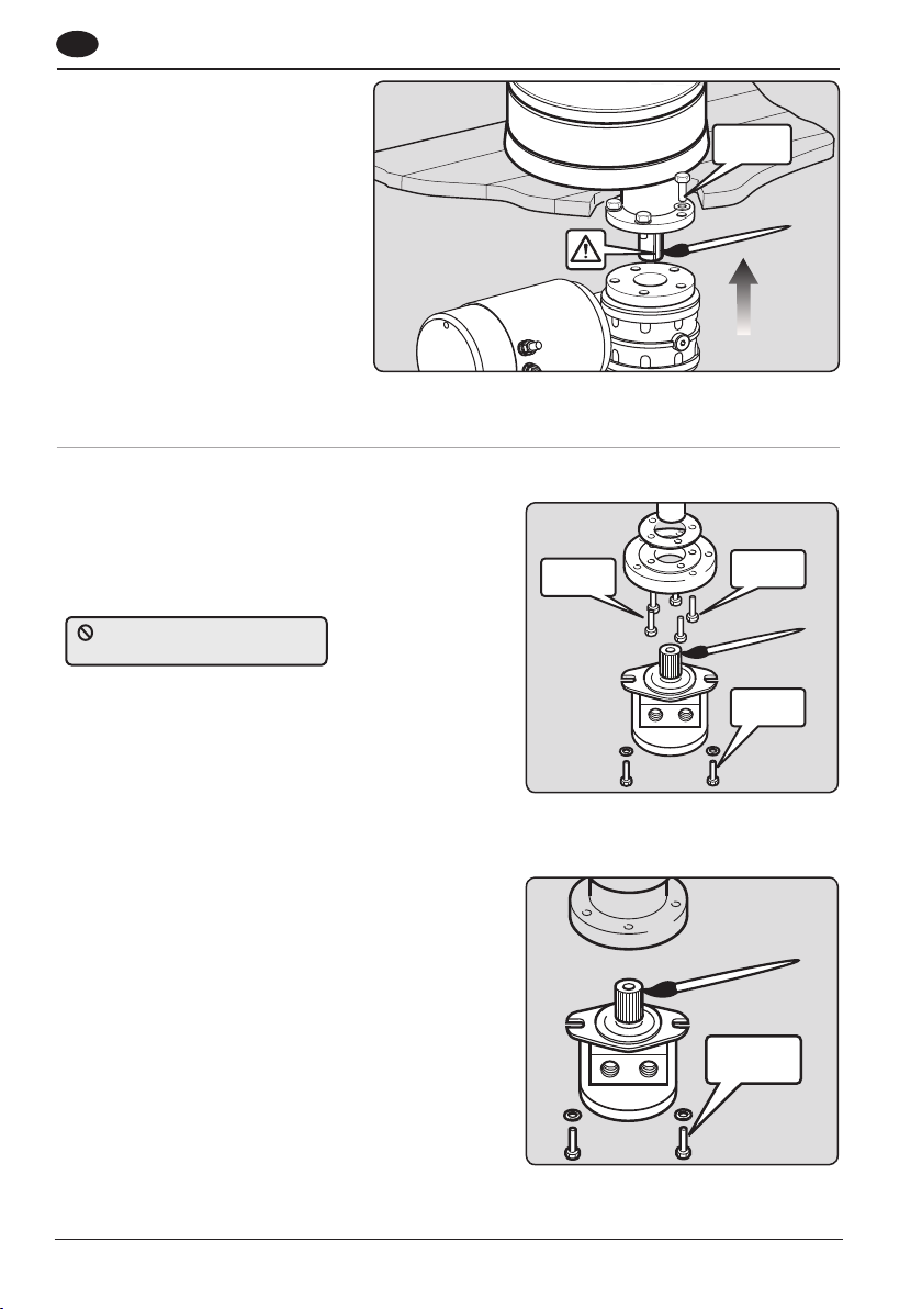
3.6 Fastenings
NOTE: Deck fastenings are not supplied.
1. Fix the winch to the deck using CSK Head, stainless steel washers and locknuts.
Use the table below to calculate the correct bolt length for your deck thickness.
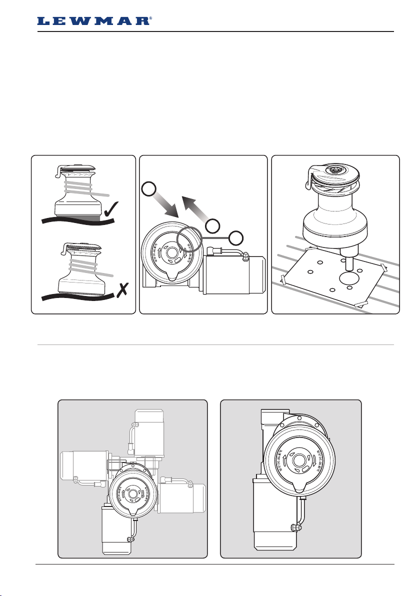
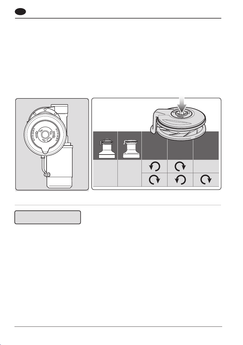
3.7 Electric winch motor/gearbox coupling
Winches 40-65
1. These winches require the base motor coupling
and shim to be fitted. Apply Loctite® threadlock
to coupling bolts (# 15), insert isolation shim and
secure to winch base plate. Assemble coupling
bolts and washers, apply Loctite® threadlock and
secure to 21Nm.
• Lightly coat the drive sha with grease. Ensure
the drive key is in place. Select the most suitable
position and slide motor/gearbox into position,
assemble bolts and washers, apply Loctite®
threadlock and secure to 43Nm.

10
43 Nm
LOCTITE
®
3.7-2
21 Nm
LOCTITE
®
43 Nm
LOCTITE
®
#15
B0678 x 5
3.8 -1
43 Nm
LOCTITE®
3.8-2
GB
Winches 68-77
2. Assemble coupling motor bolts and
washers apply Loctite® threadlock and
secure to 43Nm.
• Lightly coat the drive sha with grease.
Ensure the drive key is in place. Select
the most suitable position and slide
motor/gearbox into position, assemble
bolts and washers, apply Loctite®
threadlock and secure to 43Nm.
Winches 46-65
1. These winches require the base motor coupling and
shim to be fitted. Apply Loctite® threadlock to coupling
bolts (# 15), insert isolation shim and secure to winch
base plate. Assemble coupling bolts and washers,
apply Loctite® threadlock and secure to 21Nm.
• Lightly coat the motor splined input sha with grease
and slide motor into position, assemble bolts and
washers, apply Loctite® threadlock and secure to
43Nm.
Hydraulic drive unit case drains
DO NOT need to be fitted.
3.8 Hydraulic winch coupling
Winches 68-111
2. Lightly coat the motor input sha with grease and
slide motor into position. Assemble coupling bolts
and washers, apply Loctite® threadlock and secure to
43Nm.
NOTE: See section 5 for hydraulic connection specifica-
tions.

Lewmar OCEAN & EVO® Electric/Hydraulic Winches ref B2303 Iss.14 | 11
4.1 Electric cable selection
The cable table gives recommended cable sizes based
on total length of cable required, from the battery, fol-
lowing the route of the cables. Lewmar recommends to
source and install cable that meets the requirements of
the standards and regulations relevant to the installa-
tion and codes of practice.
• Winch performance is directly related to cable
size and length. The cable sizes are calculated
so that the maximum overall voltage drop do not
exceed10% over the whole cable installation.
4.2 Wiring
Plan the installation to suit the controls and give the operator a full view of the winch. The wiring system should
be of the fully insulated type, which avoids possible electrolytic corrosion problems. We recommend the use of
type III stranded, tinned copper wire with copper crimp terminals. Most modern installations are negative return
(negative ground) but polarity should be checked.
Overload protection, in the form of the circuit breaker/fuse (not supplied), must be built into the winch wiring
circuit.
NOTE: The circuit breaker should be positioned close to the battery in a dry, readily accessible place.
• The breaker must be manually reset should an overload occur that causes it to trip to the off position.
• If you are not sure you understand these guidelines, seek professional help. Ensure that the installation
complies with USCG, ABYC, NMMA or other local regulations.
4.3 Control switch installation
Follow the mounting instructions supplied with the switch.
DO NOT confuse cable Length
with the length of the vessel!
4. Electrical Wiring
WARNING!
CABLE SIZE
12V DC
CABLE SIZE
24V DC
TOTAL CABLE
DISTANCE
50 mm2 (1/0 AWG) 25 mm2 (3 AWG) up to 7 m (23 ft)
70 mm2 (2/0 AWG) 35 mm2 (2 AWG) 7-10 m (23-33 ft)
70 mm2 (2/0 AWG) 50 mm2 (1/0 AWG) 10-15 m (33-49 ft)
95 mm2 (3/0 AWG) - 15-20 m (49-66 ft)
WARNING! All electrical work must be
carried out with the power OFF. Isolate
the winch using circuit breaker/isolator.
When wiring Lewmar electric motor into the ship’s
electrical system the following caution must be
taken.
When tightening the front nut hold the back nut with
a separate wrench to make sure the back nut does
not turn. If the back nut turns, serious damage will
occur, voiding Lewmar’s warranty on the electric
motor.
4.4 Electric motor terminal connections
DO NOT over tighten electric motor
terminal nuts.
Tighten M8 front nut to a torque setting of
15Nm to 18Nm

12
3
2
15
4
GB
4.6 Type “E” - 40/46/48 + EVO® 50 electric 12/24V
• This simple installation of a power drive unit, motor and switch gear controls the winch by a single
direction contactor, which can be a contactor housed in a waterproof box or a stand alone encased unit.
• The motor thermal trip is connected to monitor motor temperature.
• Manual override facility is still available for backup, or as a means of experiencing traditional sailing.
• Two plus one speed comes as standard control which gives two speed manual drive (handle) plus one
speed electric drive.
4.7 Type “ELS” - 40-65 electric 12/24V
• This Electric Load Sensing installation controls the winch by Lewmar’s unique Overload Protection Control
Box, this allows the winch to be operated up to a set current relative to maximum load.
4.8 Type “ELS” - 68-77 + EVO® 80 electric 12/24V
• This installation controls the winch by Lewmar’s unique Overload Protection & Autoshi Control Box. This
allows the winch to be started in 1st and if reaches the Safe Working Load, for the winch size and gear, will
automatically shi the winch into 2nd gear for complete load control.
• In the case of a 3 speed winch the switch must be re-selected to achieve 3rd gear.
4.9 Electric deck switches
• For the latest information and list of electric deck switches visit: www.lewmar.com
4.5 Typical electrical layout
NOTE: This is not a wiring diagram.
1. Position the circuit breaker close to
the battery.
2. Route 2 cables from battery to the
control box.
3. Attach motor cables to control box
using recommended cable sizes.
4. Position the control box near the
winch (± 1 metre) in a dry area for
watertight security and accessible
for maintenance.
5. Position deck switches in view of
the winch. Route wire and attach to
control box.

Lewmar OCEAN & EVO® Electric/Hydraulic Winches ref B2303 Iss.14 | 13
3
4
Electric Deck
Switch
Thermal
Switch
3
4
Fused 3A
Contactor Box
12V - 18000301
24V - 18000302
Thermal
Switch Fuse
3A
Contactor
12V - 68000933
24V - 68000934
Fuse
3A
Thermal
Switch
Battery
Isolator
Circuit Breaker
(see manual)
Battery
12/24VDC
D1
D2
A2
D1
D2
A2
D1
D2
A2
1
2
3
4
3
4
1
2
1
2
1
2
MOTOR + BATT +
MOTOR +
BAT T+
Thermal
Switch
A1
F2
A2
F1
Cable link - Use same
size & type as main
cables, if not fitted.
40-50 EVO®WINCH
‘E’ SERIES CONTACTOR ONLY
40-50 EVO®WINCH
ELS CONTROL BOX
40-50 EVO®WINCH
‘E’ SERIES CONTACTOR BOX
55-65 EVO®WINCH
ELS CONTROL BOX
1
3
4
2
Fused 3A
4.10 Wiring diagram 40-65
Switch wire thickness: 1.5 mm2 (16 AWG)

14
68/77 + EVO® 70/80 WINCH
ELS CONTROL BOX
GB
4.11 Wiring diagram 68-77 + EVO® 70/80
Switch wire thickness: 1.5 mm2 (16 AWG)

Lewmar OCEAN & EVO® Electric/Hydraulic Winches ref B2303 Iss.14 | 15
Fig 5.1-1
OCEAN EVO®
Motor
Speeds Port A Port B
46 45 1 A B
48 50 1 A B
50 - 1 A B
54 55 1 A B
58 - 1 A B
65 65 1 A B
68 70 2-3 A B
77 80 2-3 A B
88 90 2-3 A B
111 - 2-3 A B
5- Hydraulic System
5.1 Installation
NOTE: Hydraulic system installation is NOT covered in
this publication.
Lewmar hydraulic winches have been designed for
ease of installation and follow a straight forward
hydraulic and mechanical installation procedure.
Fig 5.1-1 shows typical hydraulic circuit for a winch
with the Lewmar Commander Power System or
equivalent.
The purpose of this manual is to provide the reader
with sufficient information to install and operate a
hydraulic winch. It assumes the reader will be familiar
with sailing cra, marine hydraulics, mechanical
installation and safety requirements. If in any doubt
consult a qualified marine engineer.
WARNING!
The installation of hydraulic systems requires a high
level of cleanliness. The ingress of dirt will danger-
ously impair the safe operation of the system and
cause premature wear of hydraulic components.
5.2 Hose types
NOTE: Hoses and connectors are not supplied.
For reliable operation and safety it is essential to use reinforced braid hose for connecting to the motor A and B
ports which conforms to SAE100R7 or ISO D1S3949 safety requirements.
The recommended hose sizes are:
• Up to 15m (50) 12mm (1/2”)
• Over 15m (50) 16mm (5/8”)
• Safe working pressure : see performance graphs section 6.
• Minimum recommended bend radius 150mm (6”)
5.3 Hydraulic drive unit
NOTE: Refer to your installed hydraulic system
manual for hydraulic drives.
This table refers to Lewmar Commander system port
connections only.
The Lewmar hydraulic motor ports are: A & B ports
½” BSP.

16
GB
6- Operation
6.1 Powered winch overview
Electric 40-65 and Hydraulic 46-65 + EVO® 45-65
These are single speed powered winches and manual 2 speed, these winches employ an override ratchet gearing
for safety when winching manually.
• To operate winch press the deck switch.
Electric 68-77 + EVO® 70-80 and Hydraulic 68-111 + EVO® 70-110
These are 2 or 3 speed powered and manually operated, they will not drive electrically while the winch lock-in
handle is in the drive socket.
2 Speed Winch operation
• Autoshi (Standard)
• To engage winch press the deck switch, first gear will engage and centre spindle will rotate counter-
clockwise. When load increases it will automatically switch to the next gear.
Optional 2nd gear switch
• To engage winch in first gear press the deck switch, centre spindle will rotate counter-clockwise.
• To engage second gear press second gear deck switch, when engaged the centre spindle rotates
clockwise.
3 Speed winch operation
• Autoshi (Standard)
• Push winch base button in. To engage winch, press the deck switch, first gear will engage and centre
spindle will rotate clockwise. When load increases it will automatically switch to 2nd gear. The winch base
button will disengage and centre spindle will turn counter-clockwise.
• To engage third gear press the deck switch again, when engaged the central spindle will rotate clockwise.
Optional 2nd gear switch
• Push winch base button in. To engage winch in first gear press the 1st gear deck switch, centre spindle will
rotate clockwise.
• To engage 2nd gear press the 2nd gear deck switch, when engaged centre spindle rotates counter-
clockwise and the winch base button will disengage.
• To engage third gear press the 1st gear deck switch again, when engaged the central spindle will rotate
clockwise.
WARNING! Always remove
handle when not in use.
WARNING! Isolate the winch using circuit
breaker/isolator when not in use.

Lewmar OCEAN & EVO® Electric/Hydraulic Winches ref B2303 Iss.14 | 17
6.2-1 6.2-3
6.2-2
OCEAN EVO® EVO®
6.2-4 6.2-5
EVO®
WARNING! Always remove
handle when not in use.
WARNING! Never hold the incoming rope
to the winch while the winch is operated.
Only control the rope leaving the winch.
6.2 Adjusting self tailers
To adjust the position of the feeder arm, remove top cap and feeder arm.
1. OCEAN - Unscrew the top cap anti-clockwise and remove feeder arm.
2. EVO® - Unscrew the top cap anti-clockwise and remove feeder arm. Ensure O ring remains in top cap
groove.
3. Rotate stripper ring to required position. Adjust the feeder arm so that the rope tails into a secure area
away from the incoming line.
4. Replace feeder arm and top cap.
5. The turn leading from the drum must be passed across the
stripper mechanism as shown, and placed correctly into the
spring jaws.
• There must be a minimum of three turns of rope on the drum.
• Release the rope from the jaw set with care as load will be
present, ease the line away with care, then remove from the
drum.
• The jaws are designed to accept a range of rope diameters. The
winch should only be used with ropes of the sizes recommended.
• Use the winch handle or power switch to operate the winch.

18
Cutout (500 kg)
(A) Line Speed (m/min)
(C) Load (kg)
(B) Current (Amp)
OCEAN 40 + EVO™ 40 - 12V
Cutout (500 kg)
(A) Line Speed (m/min)
(C) Load (kg)
(B) Current (Amp)
OCEAN 40 + EVO™ 40 - 24V
Cutout (800 kg)
(A) Line Speed (m/min)
(C) Load (kg)
(B) Current (Amp)
OCEAN 46 + EVO™ 45 - 12V
Cutout (800 kg)
(A) Line Speed (m/min)
(C) Load (kg)
(B) Current (Amp)
OCEAN 46 + EVO™ 45 - 24V
Cutout (1250 kg)
(A) Line Speed (m/min)
(C) Load (kg)
(B) Current (Amp)
OCEAN 50 - 12V & 24V
Cutout (1000 kg)
(A)
Line Speed (m/min)
(C) Load (kg)
(B) Current (Amp)
OCEAN 48 + EVO™ 50 - 12V & 24V
GB
6.3 Electric performance
The following graphs show line speed and amperage draw relative to the load applied. Each control box will cut
out at a set current relative to maximum load.
(A) Line speed (m/min)
(B) Current (Amp)
(C) Load (kg)

Lewmar OCEAN & EVO® Electric/Hydraulic Winches ref B2303 Iss.14 | 19
Cutout (1450 kg)
(A) Line Speed (m/min)
(C) Load (kg)
(B) Current (Amp)
OCEAN 58 - 12V & 24V
Cutout (1580 kg)
(A) Line Speed (m/min)
(C) Load (kg)
(B) Current (Amp)
OCEAN 65 + EVO™ 65 - 12V & 24V
Cutout (1814 kg)
(A) Line Speed (m/min)
(C) Load (kg)
(B) Current (Amp)
OCEAN 68/3 + EVO™ 70 - 24V
Cutout (1350 kg)
(A) Line Speed (m/min)
(C) Load (kg)
(B) Current (Amp)
OCEAN 54 + EVO™ 55 - 12V & 24V
Cutout (2721 kg)
(A) Line Speed (m/min)
(C) Load (kg)
(B) Current (Amp)
OCEAN 77/3 + EVO™ 80 - 24V

20
(C) Line Speed
(A) Load
(m/min)
(B) Pressure (D) Flow
(l/min)
(gal/min)
(bar)
(psi)
(/min)
(kg)(lbs)
(C) Line Speed
(A) Load
(m/min)
(B) Pressure (D) Flow
(l/min)
(gal/min)
(bar)
(psi)
(ft/min)
(kg)(lbs)
(C) Line Speed
(A) Load
(m/min)
(B) Pressure (D) Flow
(l/min)
(gal/min)
(bar)
(psi)
(ft/min)
(kg)(lbs)
OCEAN 46 + EVO® 45
OCEAN 48 + EVO® 50
OCEAN 50
GB
6.4 Hydraulic performance
The following graphs show line speed and load characteristics against hydraulic flow and pressure. The following
graphs show the maximum performance envelope. Refer to trouble shooting (section 9) if performance is inferior.
(A) Load / (B) Pressure / (C) Line Speed / (D) Flow
• Safe Working Loads (SWL) for hydraulic winches are lower than hand controlled winches due to
significantly higher input/torque.
• If winch models 68-111 are installed with an Autoshi Commander unit, only one deck switch may be
required. Winch models 46-64 + EVO® 45-65 are single switch operation only. Refer to Commander manual
for deck switch installation details.
This manual suits for next models
13
Table of contents
Other Lewmar Winch manuals
Popular Winch manuals by other brands

Motomaster
Motomaster ELIMINATOR 140-0050-6 instruction manual

Ramsey Electronics
Ramsey Electronics WILDCAT 80,000 LB Series Operating, Service and Maintenance Manual

Superwinch
Superwinch TIGER SHARK manual

Warrior Winches
Warrior Winches C10000NH owner's manual

Badland Winches
Badland Winches 68146 Installation and operating instructions

Quadratec
Quadratec Q9000 Synthetic Operator's guide