Lexivon LX-190 User manual

LX-190 USER MANUAL
2~26 Nm/17.7~230.1 in.-lb.
MINI 1/4-INCH DRIVE CLICK
TORQUE WRENCH

ATTENTION
• Please read and understand entire manual,
including all safety information, before using
torque wrench. This tool is a precision
measuring instrument. Handle with care
and store properly. Do not attempt to
increase the leverage of this wrench with
any other device. Failure to follow all the
instructions could result in damage to
torque wrench, property damage, or
physical injury.
• At low torque settings, click might be
subtle; pull wrench slowly to observe click -
Learn to hear and feel the click.
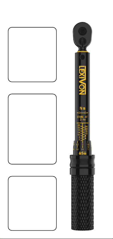
• Wrench is shipped ready to use, calibrated
and tested to an accuracy of +/- 4% in
CLOCKWISE direction and +/- 6% in
COUNTERCLOCKWISE direction. To
maintain this accuracy, it is crucial that the
wrench is stored at the lowest torque
setting, 2 Nm (17.7 in.-lb.). This setting
relieves extra tension on the internal spring,
reducing fatigue that can adversely affect
accuracy.

A
B
D
C
INTRODUCTION
A. Quick Release Button
B. 1/4-Inch Square Drive
C. Left/Right Ratchet Lever
D. Wrench Body
Fig. A

This is a dual-range torque wrench marked with
Newton-meters (Nm) and inch-pounds (in.-lb.)
on opposite sides of the wrench body. The
micrometer scale has two rows, the top row is for
Nm and the bottom row is for in.-lb.
The torque scale is marked on the wrench body
with more precise subdivisions on the knurled
handle (Fig. B) throughout the instruction manual
the wrench body scale will be referred to as the
“main scale” and the knurled handle scale will be
referred to as the “micrometer scale”.
Wrench Body:
Main Scale [Nm]
Sec. Scale [In-Lb]
Micrometer Scale:
Top Row [Nm]
Bottom Row [In-Lb]
Sliding Lock
Knurled Handle
Fig. B
Wrench measures torque in clockwise
and counterclockwise directions.
SETTING TORQUE READING

NEWTON METERS
(Example reading: 15 Nm)
2. Turn the knurled
handle until its top
edge is even with the
horizontal “14” mark
on the main scale,
while the “0” mark on
the micrometer scale is
centered on the vertical
line of the main scale.
3. The micrometer scale’s
top row divides the main
scale markings into 10
divisions. Every micrometer
scale marking equals 0.2
Nm, also known as the
minimum increment. To
increase the torque from
14 to 15, turn the
micrometer knurled handle
clockwise until the “1.0” mark of the top row is
centered on the vertical line of the main scale.
14 Nm (main scale) + 1 Nm (micrometer
scale) = 15 Nm
1. Slide down locking
collar to enable
micrometer scale
adjustment.
Use top row of
Micrometer scale

Setting desired torque on the In.-Lb. scale uses the
same procedure described above for Nm scale.
The micrometer scale’s bottom row divides the
main scale markings into 10 divisions. Every
marking equals 1.77 (1.8) In-Lb, also known as
the minimum increment.
To set a torque value of 200 In-Lb, turn the knurled
micrometer handle until the top is aligned with
"194.7" mark on main scale and the “0” mark on
the bottom row of the
micrometer scale is
centered on the vertical
line of the main scale.
To increase torque from
194.7 to 200, turn the
micrometer handle
clockwise until the 5.3
mark is centered on the
vertical line of the main
scale. 194.7 In-Lb (main
scale) + 5.3 In-Lb
(micrometer scale) = 200
In-Lb. Slide up locking
collar to maintain torque
setting. The wrench is
now set to measure 200
In-Lb of torque and is
ready to use.
INCH POUNDS
(Example reading: 200 In-Lb)
4. Slide up locking collar to maintain the torque
setting. The wrench is now set to measure 15 Nm
of torque and is ready to use.
5. IMPORTANT – Store the wrench at its lowest
setting 2 Nm (17.7 in.-lb.) to maintain torque
accuracy.
Use bottom row of micrometer scale

WRENCH OPERATION
1. Install proper socket/attachment on the square
drive and apply to nut/bolt. Make sure to keep
your tightening hand centered on the knurled
handle for accurate results.
2. Operate the wrench to tighten nut/bolt and
slow operation when they become snug to a
smooth and steady pull. When a ‘CLICK’ or
‘IMPULSE’ is heard or felt; stop pulling wrench and
release pressure on handle.
3. Wrench will automatically reset for next
operation after pressure is released.
STOP
Torque is measured in both clockwise
And counterclockwise directions.
“CLICK”

IMPORTANT OPERATION NOTICE
Operating wrench too quickly or with
too much force may cause you to miss
the exact torque setting. Do not
continue to pull after torque setting is
reached. Doing so will damage the
wrench's internal mechanism.
At low torque settings, the click can be
subtle. Use the wrench in a quiet
environment - Learn to hear and feel
the click.
Do not use the wrench to break free
stuck fasteners. Tighten/adjust sliding
lock and knurled handle by hand only.
Wrench does not measure torque
below 2 Nm/17.7 in.-lb.

MAINTENANCE AND STORAGE
1. If the wrench has
not been in use for a
long time, operate it
several times at a low
torque setting. This
will allow internal
lubricant to recoat
internal components.
2. Keep the Torque
Wrench Scale at the
lowest setting when
not in use. The lowest
setting: 2 Nm mark
on the main scale and
‘0’ mark on the
micrometer scale. DO
NOT turn handle
below lowest torque
setting.
3. Clean the wrench
by wiping it with a
clean, dry, lint-free
cloth. Do not immerse
in any liquid or
cleaner, as it can
damage the wrench's
internal components.

TORQUE UNIT CONVERSION TABLE
CAUTION:
STORE AT LOWEST SETTING - To maintain
calibration, set wrench to lowest torque value
before storage.
OPERATE SLOWLY - Wrench “clicks” to notify
when torque value is reached. Wrench does not
stop applying force automatically.
LISTEN AND FEEL - At low torque settings
clicks is subtle. Learn to hear and feel the click.
PRECISION TOOL - Do not use for extreme
operation like breaking loose stuck fasteners.
PRACTICE FIRST - Try wrench on a non-critical
fastener first to learn how it works.
CONVERSIONS
0.138 m-kg
12.0 in.-lb.
1.35 Nm
13.8 cm-kg
1 Nm =
8.85 in.-lb.
0.737 ft.-lb. 0.0833 ft.-lb.
0.102 m-kg
10.2 cm-kg
1 in.-lb. = 1 ft.-lb. =
0.113 Nm
0.0115 m-kg
1.15 cm-kg
INCH
POUNDS
(in.-lb.)
FOOT
POUNDS
NEWTON
METERS
(Nm)
1
2
3
4
5
6
7
8
9
10
11
12
13
14
15
16
17
18
19
20
21
22
23
24
25
26
1
2
3
4
5
6
7
8
9
10
11
12
13
14
15
16
17
18
19
20
21
22
23
1.36
2.71
4.07
5.42
6.78
8.13
9.49
10.85
12.20
13.56
14.91
16.27
17.63
18.98
20.34
21.69
23.05
24.40
25.76
27.12
28.47
29.83
31.18
12
24
36
48
60
72
84
96
108
120
132
144
156
168
180
192
204
216
228
240
252
264
276
8.85
17.70
26.55
35.40
44.25
53.10
61.96
70.81
79.66
88.51
97.36
106.21
115.06
123.91
132.76
141.61
150.46
159.31
168.16
177.01
185.87
194.72
203.57
212.42
221.27
230.12
0.74
1.48
2.21
2.95
3.69
4.43
5.16
5.90
6.64
7.38
8.11
8.85
9.59
10.33
11.06
11.80
12.54
13.28
14.01
14.75
15.49
16.23
16.96
17.70
18.44
19.18
1.13
2.26
3.39
4.52
5.65
6.78
7.91
9.04
10.17
11.30
12.43
13.56
14.69
15.82
16.95
18.08
19.21
20.34
21.47
22.60
23.73
24.86
25.99
FOOT
POUNDS
10
20
30
40
50
60
70
80
90
100
110
120
130
140
150
160
170
180
190
200
210
220
230
INCH
POUNDS
(in.-lb.)
0.83
1.67
2.50
3.33
4.17
5.00
5.83
6.67
7.50
8.33
9.17
10.00
10.83
11.67
12.50
13.33
14.17
15.00
15.83
16.67
17.50
18.33
19.17
NEWTON
METERS
(Nm)
NEWTON
METERS
(Nm)
INCH
POUNDS
(in.-lb.)
FOOT
POUNDS

FOR ANY HELP YOU MIGHT NEED
PLEASE DON’T HESITATE TO CONTACT US
Register your new product online within 90 days from the purchase at:
Table of contents
Other Lexivon Power Tools manuals
Popular Power Tools manuals by other brands

Hakko Electronics
Hakko Electronics FR-410 instruction manual

Hakko Electronics
Hakko Electronics FM-2030 instruction manual

National Flooring Equipment
National Flooring Equipment 550 Service manual

Worx
Worx WX041 Original instructions

Bosch
Bosch GWS Professional 7-115 E Original instructions

HIKOKI
HIKOKI CE 16SA Handling instructions

Stanley
Stanley FATMAX SBD715 manual

Porter-Cable
Porter-Cable NS100A instruction manual

B&C Eagle
B&C Eagle NS1840-II Operation and maintenance manual

Ingersoll-Rand
Ingersoll-Rand ELB2612N Product information

Stanley
Stanley STRR1200 instruction manual

Black & Decker
Black & Decker BDPR400-LA RapidRoller instruction manual