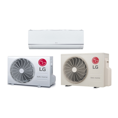
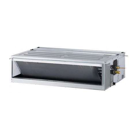
LG 6CIM0-01B Product guide

Indoor unit
R410A
6CIM0-01B (Replaces 6CIM0-01A)

Introduction
Preface
New era brings the more sophisticated and advanced buildings which in turn demands for specialized and optimized direct
expansion air conditioning systems. Also energy efficiency, low noise and low maintenance are the features which are
essential for these systems.
As a part of vertical integration LG makes all the key components in house, which gives us an edge to LG to make better
and latest technology products with best quality in optimized time.
systems are equipped with inverter technology and R410A refrigerant which is perfect solution to vari-
ous installation locations.
This Engineering product data book incorporates information about the product itself, and installation, designing for
system.
The comprehensive study of this book will improve your knowledge about the system and its application in detail.
LG Electronics Inc.
Air Conditioning & Energy Solution Company
Indoor unit

General information
1. Model line up
2. Nomenclature
3. Appearance
Indoor unit

Heat pump 60Hz/R410A _ 1
General information
Indoor unit
1. Model line up
2.64
(9)
5.28
(18)
3.52
(12)
ARTCOOL
Mirror
Category
Model names
Capacity, kW(kBtu/h Class)
Chassis
Wall mounted
Ceiling cassette
SB
SC
SB
SC
TR
TQ
AMNW09GDBL0
[LMN096HVT]
AMNW12GDBL0
[LMN126HVT]
AMNW18GDCL0
[LMN186HVT]
AMNW09GDBR0
[LMAN096HVT]
AMNW12GDBR0
[LMAN126HVT]
AMNW09GB1A0
[LMDN095HV]
AMNW12GB1A0
[LMDN125HV]
AMNW12GTRA0
[LMCN125HV]
AMNW18GDCR0
[LMAN186HVT]
AMNW18GTQA0
[LMCN185HV]
AMNW18GB2A0
[LMDN185HV]
B1
B2
Low
static
pressure
(Slim)
Ceiling
concealed
duct

2_ Heat pump 60Hz/R410A
General information
Indoor unit
2.1 Global model names
AMN W G
09 BDL0
Serial number
Indicates that this is multi system indoor unit using R410A
Model type
W : DC Inverter heat pump
Ex) 9,000 Btu/h Class →'09', 18,000 Btu/h Class →'18'
Cooling/heating capacity
Electrical rating
G: 208/230V, 1Ø, 60Hz
Chassis name
Indoor unit type
D : Wall Mounted, ART COOL Mirror
T : Ceiling cassette, B : Ceiling concealed duct
Function
A : Basic, L : Plasma (Wall mounted)
C : Plasma(ceiling cassette)
ART COOL(Mirror) type front panel color
R : Mirror
2. Nomenclature

Heat pump 60Hz/R410A _ 3
General information
Indoor unit
3. Appearance
3.1 Indoor units
• ART COOL Mirror
• Ceiling Cassette 4-way• Ceiling Concealed Duct – Low static pressure
AMNW09GB1A0 [LMDN095HV]
AMNW12GB1A0 [LMDN125HV]
AMNW18GB2A0 [LMDN185HV]
• Wall Mounted
AMNW12GTRA0 [LMCN125HV]
AMNW18GTQA0 [LMCN185HV]
AMNW09GDBR0 [LMAN096HVT]
AMNW12GDBR0 [LMAN126HVT]
AMNW18GDCR0 [LMAN186HVT]
AMNW09GDBL0 [LMN096HVT]
AMNW12GDBL0 [LMN126HVT]
AMNW18GDCL0 [LMN186HVT]
3.2 Control system(standard)
These controllers will be provided with the respective indoor units.
Type
Simple
wired remote
controller
Wireless remote
controller
Wireless remote
controller
Individual controller Applicable model
Ceiling concealed duct
PQRCVCL0QW
PQWRHDF0
Ceiling cassette
Wall mounted
ART COOL Mirror

1. Wall Mounted
2. ART COOL Mirror
3. Ceiling cassette 4-way
4. Ceiling concealed duct - Low static pressure
Indoor unit

Wall Mounted
1. List of functions
2. Specifications
3. Dimensions
4. Piping diagrams
5. Wiring Diagrams
6. Capacity Tables
7.
Air flow and temperature distributions (reference data)
8. Sound levels
9. Controller
10. Installation
Indoor unit

1. List of functions
Note :
1. * : These functions need to connect the wired remote controller.
O : Applied, X : Not applied
Accessory model name : Installed at field, ordered and purchased separately by the corresponding model name, supplied with separate
package.
Wall mounted _ 1
Indoor Units
Indoor unit
Category Functions
AMNW09GDBL0 [LMN096HVT]
AMNW12GDBL0 [LMN126HVT]
AMNW18GDCL0 [LMN186HVT]
Air flow
Air supply outlet 1
Airflow direction control (left & right) Auto
Airflow direction control (up & down) Auto
Auto swing (left & right) O
Auto swing (up & down) O
Airflow steps (fan/cool/heat) 5 / 6 / 6
Chaos wind(auto wind) O
Jet cool/heat O / O
Swirl wind X
Air purifying
Triple filter (Deodorizing) X
Plasma air purifier O
Allergy Safe filter X
Long-life prefilter (washable / anti-fungus)
O
Installation
Drain pump X
E.S.P. control X
Electric heater X
High ceiling operation X
Auto Elevation Grille X
Reliability
Hot start O
Self diagnosis O
Soft dry operation O
Convenience
Auto changeover X
Auto cleaning O
Auto operation(artificial intelligence) O
Auto Restart O
Child lock* O
Forced operation O
Group control X
Sleep mode O
Timer(on/off) O
Timer(weekly)* O
Two thermistor control* O
Individual
controller
Wired remote controller PQRCVSL0 / PQRCVSL0QW
Deluxe wired remote controller X
Simple wired remote controller PQRCVCL0Q / PQRCVCL0QW
Simple Wired remote controller(for hotel use)
X
Wireless remote controller O
Network
Solution
General central controller (Non LGAP) X
Network Solution(LGAP) O
Dry contact PQDSA(1)/PQDSB(1) / PQDSBC / PQDSBNGCM1
PI 485(for Indoor Unit) X
Special
function kit
Zone controller X
CTI(Communication transfer interface) X
Electronic thermostat X
Others Remote temperature sensor X
Telecom shelter controller X

Note :
1. Wiring cable size must comply with the applicable local and national code.
2. Due to our policy of innovation some specifications may be changed without notification.
3. Sound Level Values are measured at Anechoic chamber.
Therefore, these values can be increased owing to ambient conditions during opration.
4. Acceptable operating voltage: 187V-253V
Model Name AMNW09GDBL0
[LMN096HVT]
AMNW12GDBL0
[LMN126HVT]
AMNW18GDCL0
[LMN186HVT]
Power Supply V, Ø, Hz 208/230, 1, 60 208/230, 1, 60 208/230, 1, 60
Capacity Nominal kW Class 2.6 3.5 5.3
Nominal Btu/h Class 9,000 12,000 18,000
Casing Color - White White White
Dimensions Body W x H x D mm 895 × 289 × 210 895 × 289 × 210 1,030 × 325 × 250
W x H x D inch
35-1/4 x 11-3/8 x 8-9/32 35-1/4 x 11-3/8 x 8-9/32 40-9/16 x 12-25/32 x 9-27/32
Net Weight Body kg (lbs) 10.0 (22.1) 10.0 (22.1) 14.5 (32.0)
Heat Exchanger
(Row x Column x Fins per inch) x No.
- (2 x 16 x 23) x 1 (2 x 16 x 23) x 1 (3 x 18 x 22) x 1
Face Area
m2(ft2) 0.22 (2.37) 0.22 (2.37) 0.29 (3.07)
Fan
Type - Cross Flow Fan Cross Flow Fan Cross Flow Fan
Air Flow Rate H / M / L m3/min 7.0 / 6.5 / 6.0 9.5 / 9.0 / 8.5 16.2 / 14.2 / 12.3
H / M / L ft3/min 247 / 230 / 212 335 / 318 / 300 572 / 501 / 434
Fan Motor
Type - BLDC BLDC BLDC
Output W x No. 14.4 x 1 14.4 x 1 76.0 x 1
Running Current A 0.20 0.20 0.30
Sound Pressure Level H / M / L dB(A) 33 / 30 / 27 39 / 36 / 31 37 / 33 / 28
Sound Power Level Cooling dB(A) - - -
Piping
Connections
Liquid mm(inch) 6.35 (1/4) 6.35 (1/4) 6.35 (1/4)
Gas mm(inch) 9.52 (3/8) 9.52 (3/8) 12.7 (1/2)
Drain (O.D. / I.D.) mm(inch) 21.5(27/32) / 16.0(5/8) 21.5(27/32) / 16.0(5/8) 21.5(27/32) / 16.0(5/8)
Safety Devices
- Fuse Fuse Fuse
-Thermal Protector for
Fan Motor
Thermal Protector for
Fan Motor
Thermal Protector for
Fan Motor
Power and Communication Cable (included Earth)
No. x AWG 4C x 18 4C x 18 4C x 18
2. Specifications
2_ Wall mounted
Indoor Units
Indoor unit

Wall mounted _ 3
3. Dimensions
Indoor Units
Indoor unit
1. Unit should be installed in compliance with the installation manual
in the product box.
2. Unit shall be grounded in accordance with the local regulations or
applicable national codes.
3. The Unit is powered from the outdoor unit. Therefore power cable
should be connected with the outdoor unit.
76, Seongsan-dong, Changwon City, Gyeongnam,
641-713, Korea
CHASSIS CODE: SB
WALL MOUNTED
AMNW09GDBL0[LMN096HVT]
AMNW12GDBL0[LMN126HVT]
Display & signal receiver
Part Name
Front panel
Air suction grille
Installation plate
Knockout hole
5
No.
2
4
3
1
Remark
Note
285(11-7/32)
50(1-31/32)
210(8-9/32)
45(1-25/32)
895(35-1/4)
341(13-15/32) 323(12-23/32) 128(5-1/32)
37(1-15/32)
790(31-3/32)
205(8-1/16)
675(26-9/16)
327(12-7/8)
422(16-5/8)
264(10-13/32)
70(2-3/4)
[Unit : mm(inch)]

3. Dimensions
1. Unit should be installed in compliance with the installation manual
in the product box.
2. Unit shall be grounded in accordance with the local regulations or
applicable national codes.
3. The Unit is powered from the outdoor unit. Therefore power cable
should be connected with the outdoor unit.
76, Seongsan-dong, Changwon City, Gyeongnam,
641-713, Korea
CHASSIS CODE: SC
WALL MOUNTED
AMNW18GDCL0[LMN186HVT]
Display & signal receiver
Part Name
Front panel
Air suction grille
Installation plate
Knockout hole
5
No.
2
4
3
1
Remark
Note
[Unit : mm(inch)]
250(9-27/32)
1030(40-9/16)
325(12-25/32) 210(8-9/32)
Ø 70(2-3/4)
Ø70(2-3/4)
69(2-23/32)
56(2-7/32)
Right rear
piping
Left rear
piping
Installation Plate
Measuring Tape
Measuring Tape
Hanger
Place a level on raised tab
Unit Outline
207(8-5/32)
105(4-1/8)
460(18-1/8) 570(22-7/16)
4
5
4_ Wall mounted
Indoor Units
Indoor unit

Gas pipe connection port
(flare connection)
Liquid pipe connection port
(flare connection)
Cooling
Heating
Thermistor for
Evaporator middle
temperature
Thermistor for
Evaporator Inlet Temperature
Thermistor for
Indoor Air Temperature
Thermistor for Evaporator
Outlet Temperature
Heat Exchanger
Cross Flow Fan
M
n
Refrigerant pipe connection port diameters
Unit : mm(inch)
Notes : Description is expressed based on Cooling mode.
Model Gas Liquid
AMNW09GDBL0 [LMN096HVT]
AMNW12GDBL0 [LMN126HVT] Ø9.52(3/8) Ø6.35(1/4)
AMNW18GDCL0 [LMN186HVT] Ø12.7(1/2) Ø6.35(1/4)
Description PCB Connector
Thermistor for Indoor Air Temperature CN_TH1
Thermistor for Evaporator Inlet Temperature
Thermistor for Evaporator Outlet Temperature CN_TH2
Thermistor for Evaporator middle temperature CN_TH3
4. Piping diagrams
Wall mounted _ 5
Indoor Units
Indoor unit

5. Wiring diagrams
Models : AMNW09GDBL0 [LMN096HVT] / AMNW12GDBL0 [LMN126HVT]
Models : AMNW18GDCL0 [LMN186HVT]
6_ Wall mounted
Indoor Units
Indoor unit

nCooling Capacity
Notes:
1. Capacities are based on the following conditions.
Corresponding refrigerant piping length : 25ft
Level difference : 0ft
2. TC : Total Capacity(kBtu/h)
SHC: Sensible Heat Capacity(kBtu/h)
Cooling Capacity
Unit Size
(kBtu/h(kW))
Outdoor
air temp.
°F DB
Indoor Air Temp. °F DB/ °F WB
68.0 / 57.2 71.6 / 60.8 77.0 / 64.4 80.6 / 66.2 86.0 / 71.6 89.6 / 75.2
TC SHC TC SHC TC SHC TC SHC TC SHC TC SHC
68.0
77.0
89.6
95.0
104.0
109.4
114.8
68.0
77.0
89.6
95.0
104.0
109.4
114.8
68.0
77.0
89.6
95.0
104.0
109.4
114.8
8.70 7.34 9.20 7.54 9.80 7.81 10.20 8.03 10.80 7.59 11.40 7.25
8.40 6.80 8.90 6.99 9.40 7.16 9.80 7.32 10.50 7.10 11.00 6.89
7.90 6.15 8.40 6.20 9.00 6.32 9.30 6.37 10.00 6.39 10.60 6.44
7.70 6.10 8.20 6.14 8.80 6.24 9.00 6.32 9.80 6.39 10.40 6.46
7.40 6.04 7.90 6.09 8.40 6.19 8.80 6.29 9.50 6.63 10.00 6.71
7.20 6.16 7.70 6.26 8.20 6.42 8.60 6.53 9.30 6.79 9.80 6.97
7.00 6.30 7.50 6.47 8.00 6.69 8.40 6.84 9.10 6.98 9.60 7.12
11.60 10.35 12.30 10.66 13.00 11.02 13.50 11.27 14.50 10.72 15.20 10.22
11.20 9.60 11.90 9.83 12.60 10.10 13.10 10.30 14.00 10.00 14.70 9.73
10.50 8.63 11.20 8.74 12.00 8.90 12.50 9.00 13.40 9.02 14.10 9.09
10.30 8.72 11.00 8.75 11.70 8.79 12.00 8.90 13.10 9.03 13.80 9.10
9.80 8.51 10.50 8.60 11.20 8.73 11.70 8.82 12.70 9.32 13.40 9.67
9.50 8.63 10.30 8.86 11.00 9.05 11.50 9.19 12.40 9.53 13.10 9.83
9.30 8.86 10.00 9.13 10.70 9.44 11.20 9.63 12.10 9.85 12.80 10.02
17.40 15.00 18.50 15.49 19.60 16.01 20.30 16.35 21.70 15.57 22.80 12.30
16.80 13.94 17.80 14.27 18.90 14.70 19.60 14.95 21.00 14.49 22.10 11.73
15.70 12.47 16.90 12.75 18.00 12.93 18.70 13.07 20.10 13.12 21.20 10.94
15.30 12.57 16.40 12.66 17.60 12.78 18.00 12.90 19.70 13.12 20.80 10.97
14.70 12.28 15.80 12.47 16.80 12.65 17.60 12.83 19.00 13.53 20.10 11.69
14.30 12.52 15.40 12.83 16.40 13.10 17.20 13.34 18.50 13.79 19.70 11.86
13.90 12.82 15.00 13.26 16.00 13.66 16.80 13.97 18.20 14.28 19.20 12.05
9.0
(2.64)
12
(3.52)
18
(5.28)
6. Capacity Tables
Wall mounted _ 7
Indoor Units
Indoor unit

Notes:
1. Capacities are based on the following conditions.
Corresponding refrigerant piping length : 25ft
Level difference : 0ft
2. TC : Total Capacity(kBtu/h)
Unit Size
(kBtu/h(kW))
Indoor air
temp.
°F DB
Outdoor Air Temp. °F WB
5 1423324350 59
TC TC TC TC TC TC TC
60.8
64.4
68.0
70.0
71.6
75.2
60.8
64.4
68.0
70.0
71.6
75.2
60.8
64.4
68.0
70.0
71.6
75.2
6.0 7.4 8.5 9.5 10.5 10.9 11.0
6.0 7.3 8.4 9.4 10.4 10.9 10.9
5.9 7.3 8.4 9.4 10.4 10.9 10.9
5.9 7.2 8.3 9.3 10.4 10.8 10.8
5.8 7.2 8.2 9.2 10.3 10.7 10.8
5.5 6.9 8.0 9.0 10.0 10.5 10.5
8.0 9.8 11.3 12.6 14.0 14.6 14.6
7.9 9.7 11.2 12.5 13.9 14.5 14.5
7.9 9.7 11.2 12.5 13.9 14.5 14.5
7.8 9.6 11.1 12.4 13.8 14.4 14.4
7.7 9.5 11.0 12.3 13.7 14.3 14.3
7.4 9.2 10.6 12.0 13.4 13.9 14.0
12.0 14.8 16.9 18.9 20.9 21.9 22.0
11.9 14.6 16.7 18.8 20.8 21.8 21.8
11.8 14.6 16.7 18.7 20.7 21.7 21.8
11.7 14.4 16.6 18.5 20.8 21.6 21.6
11.6 14.3 16.4 18.4 20.5 21.4 21.5
11.0 13.7 16.0 17.9 20.0 20.9 20.9
9.0
(2.64)
12
(3.52)
18
(5.28)
6. Capacity Tables
nHeating Capacity Heating capacity
8_ Wall mounted
Indoor Units
Indoor unit

7. Air flow and temperature distributions (reference data)
Model : AMNW12GDBL0 [LMN126HVT]
Cooling Heating
72
68
75
64
Air velocity [ft/s]
Temperature [°F]
3.3
6.6
4.9
1.6
9ft
7ft
3ft
0ft
16ft 13ft 10ft 7ft 3ft 0ft
9ft
7ft
3ft
0ft
16ft 13ft 10ft 7ft 3ft 0ft
Model : AMNW09GDBL0 [LMN096HVT]
Cooling Heating
72
68
75
64
3.3
4.9
1.6
Air velocity [ft/s]
Temperature [°F]
9ft
7ft
3ft
0ft
16ft 13ft 10ft 7ft 3ft 0ft
9ft
7ft
3ft
0ft
16ft 13ft 10ft 7ft 3ft 0ft
9ft
7ft
3ft
0ft
16ft 13ft 10ft 7ft 3ft 0ft
9ft
7ft
3ft
0ft
16ft 13ft 10ft 7ft 3ft 0ft
70 75
81
86
91
3.3
6.6
4.9
1.6
Air velocity [ft/s]
Temperature [°F]
Discharge angle : 40° Discharge angle : 50°
3.3
6.6
4.9
1.6
Air velocity [ft/s]
Temperature [°F]
70
75
81
86
91
9ft
7ft
3ft
0ft
16ft 13ft 10ft 7ft 3ft 0ft
9ft
7ft
3ft
0ft
16ft 13ft 10ft 7ft 3ft 0ft
Discharge angle : 40° Discharge angle : 50°
Wall mounted _ 9
Indoor Units
Indoor unit

Model : AMNW18GDCL0 [LMN186HVT]
Cooling Heating
3.3
6.6
4.9
1.6
Temperature [°F]
91
86
81
75
70
Air velocity [ft/s]
9ft
7ft
3ft
0ft
26ft 23ft 20ft 16ft 13ft 10ft 7ft 3ft 0ft
9ft
7ft
3ft
0ft
26ft 23ft 20ft 16ft 13ft 10ft 7ft 3ft 0ft
64
68
72
75
3.31.6
8.2
4.9
Temperature [°F]
Air velocity [ft/s]
9ft
7ft
3ft
0ft
26ft 23ft 20ft 16ft 13ft 10ft 7ft 3ft 0ft
9ft
7ft
3ft
0ft
26ft 23ft 20ft 16ft 13ft 10ft 7ft 3ft 0ft
Discharge angle : 40° Discharge angle : 50°
7. Air flow and temperature distributions (reference data)
10 _ Wall mounted
Indoor Units
Indoor unit

8. Sound levels
Overall
2.6ft
3.3ft
Microphone
Notes:
- Sound measured at 3.3ft away from the center of the unit.
- Data is valid at free field condition.
- Data is valid at nominal operation condition.
- Reference accoustic pressure 0dB=20µPa.
- Sound level will vary depending on a range of factors such as
the construction(acoustic absorption coefficient) of particular
room in which the equipment is installed.
- The operating conditions are assumed to be standard.
MLH
Sound Levels [dB(A)]
Model
AMNW09GDBL0[LMN096HVT]
AMNW12GDBL0[LMN126HVT]
AMNW18GDCL0[LMN186HVT]
33
39
37
30
36
33
27
31
28
10
20
30
40
50
60
70
80
63 125 250 500 1000 2000 4000 8000
Octave Band Sound Pressure Level (0dB = 20μPa )
Octave Band CenterFrequency (Hz)
NC-15
NC-20
NC-25
NC-30
NC-35
NC-40
NC-45
NC-50
NC-55
NC-60
NC-65
Approximate
Hearing
Threshold
10
20
30
40
50
60
70
80
63 125 250 500 1000 2000 4000 8000
Octave Band Sound Pressure Level (0dB = 20μPa )
Octave Band CenterFrequency (Hz)
NC-15
NC-20
NC-25
NC-30
NC-35
NC-40
NC-45
NC-50
NC-55
NC-60
NC-65
Approximate
Hearing
Threshold
Octave Band Center Frequency (Hz)
Octave Band Sound Pressure Level (0dB = 20μPa )
10
20
30
40
50
60
70
80
63 125 250 500 1000 2000 4000 8000
NC-15
NC-20
NC-25
NC-30
NC-35
NC-40
NC-45
NC-50
NC-55
NC-60
NC-65
Approximate
Hearing
Threshold
AMNW09GDBL0 [LMN096HVT] AMNW12GDBL0 [LMN126HVT] AMNW18GDCL0 [LMN186HVT]
Sound pressure level
Wall mounted _ 11
Indoor Units
Indoor unit

9. Controller
Wireless remote control
Display
screen
Control
panel
* Some functions may not be supported, depending on the model.
Control
panel
Display
screen
Description
a
F
Plasma button*:Plasmaster filter purifies the air
by removing mites, micro dust and pet fur.
Plasmaster Ionizer sterilize the aerial bacteria
and other harmful substances.
l
Sleep mode auto button*: Sets the sleep
mode auto operation.
e
Temperature adjustment buttons:
Adjusts the room temperature when cool-
ing and heating.
d-On/Off button: Turns the power on/off.
g
7
v
Indoor fan speed button: Adjusts the fan
speed.
f
AC
DB
E
Operation mode selection button*:
Selects the operation mode.
Cooling operation (A) / Auto operation or
auto changeover (C) / Dehumidifying oper-
ation (D) / Heating operation (B) / Air circu-
lation (E)
hN
Jet cooling/heating button*: Warms up or
cools down the indoor temperature within a
short period of time.
ijHI
Air flow direction button: Adjusts the air
flow direction vertically or horizontally.
k
S
Temperature display button: Displays the
room temperature. Press key and hold it for
longer than 5 second.
Display change °C/°F
mn
z
Timer button: Sets the current time and
the start / end time.
c
b
u
JG
P
Navigation and functions button*:
Adjusts the time and sets the special func-
tions.
J: Auto clean / G: Operates energy sav-
ing cooling / P: Adjusts the brightness of
the indoor unit display
p
-
Set/clear button: Sets or cancels func-
tions.
r-
Reset button: Resets the air conditioner
settings.
12 _ Wall mounted
Indoor Units
Indoor unit
This manual suits for next models
13
Table of contents
Other LG Air Conditioner manuals
Popular Air Conditioner manuals by other brands

Gree
Gree GMV-ND07PLS/A-T(U) Service manual

Toshiba
Toshiba RAS-10J2KV-HK owner's manual

Haier
Haier HSU-18LEK03/R2 Service manual

Hitachi
Hitachi RAS-18LH2 Service manual

Panasonic
Panasonic U-8ME2E8 Service Manual & Test Run Service Manual

RV Products
RV Products Airxcel Chillgrille 8330 634 Series installation instructions