2Floor Standing type Air Conditioner
Floor Standing Type Air Conditioner Installation Manual
TABLE OF CONTENTS
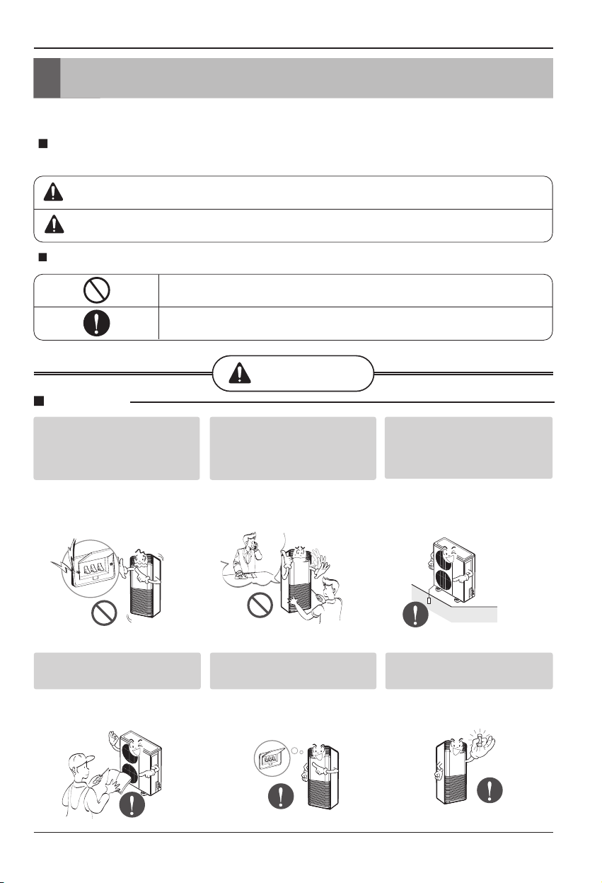
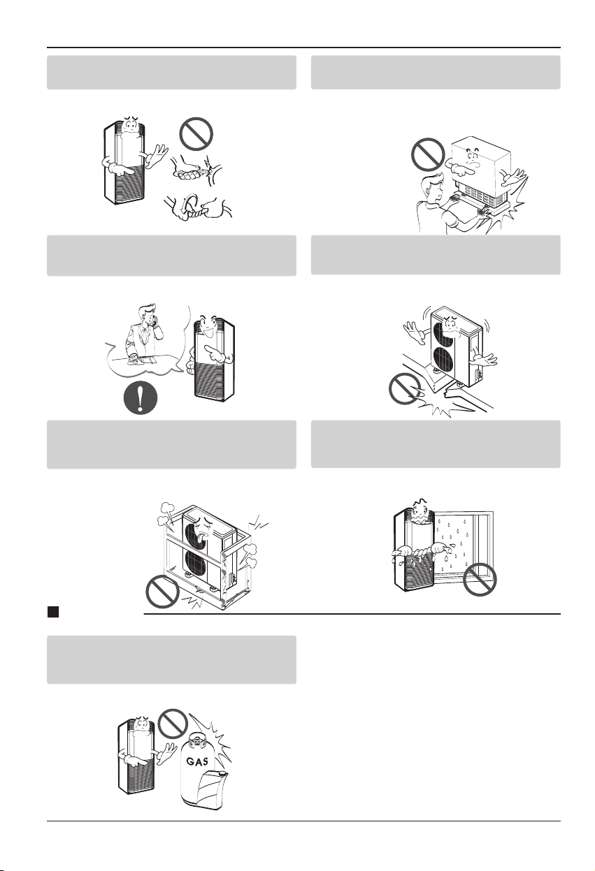
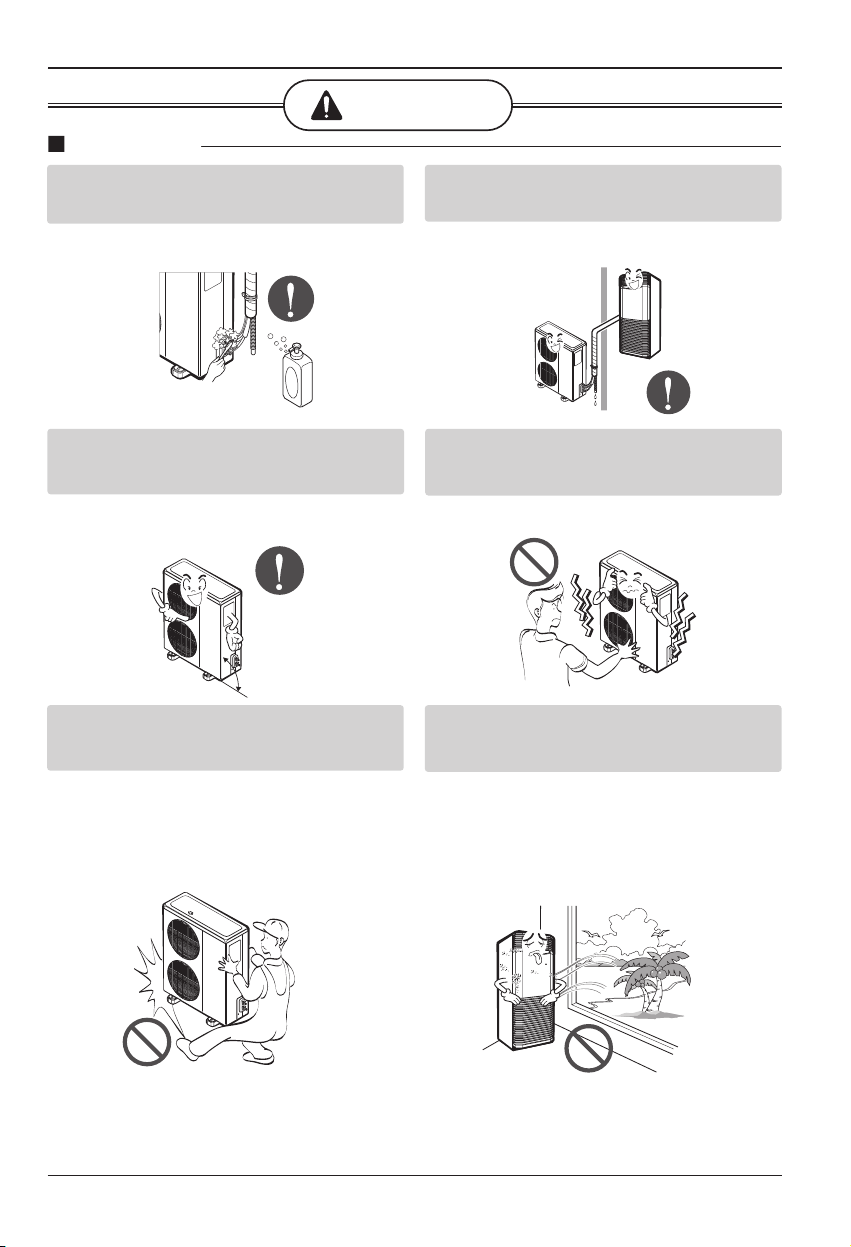
Safety Precautions
.........................................................................................3
Installation of Indoor, Outdoor Unit .............................................................7
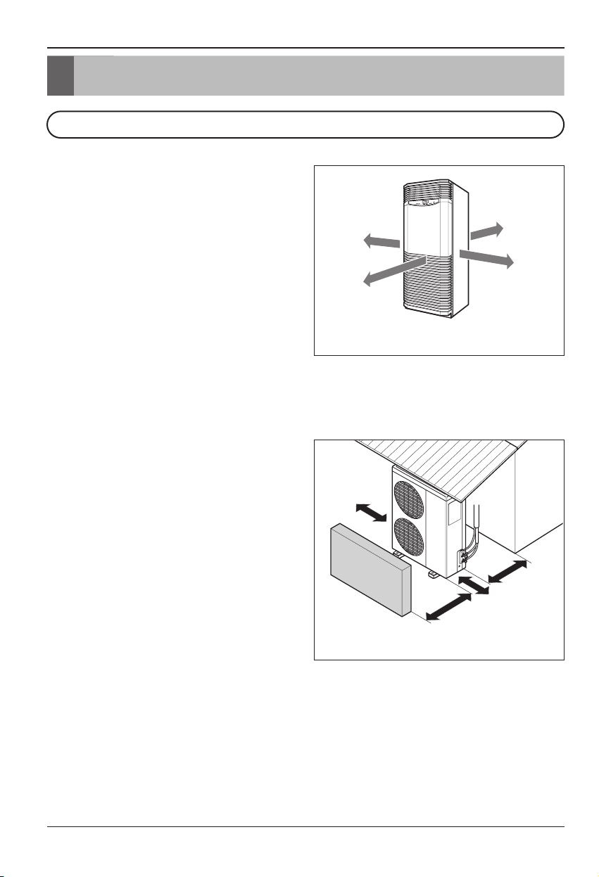
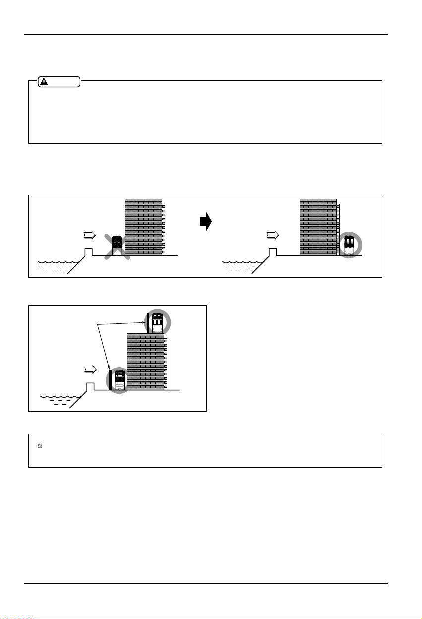
1) Selection of the best location................................................................................................................................7
2) Indoor Unit Installation .........................................................................................................................................10
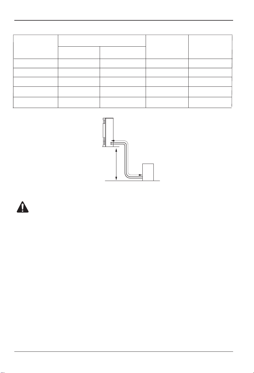
3) Outdoor unit installation .......................................................................................................................................10
4) Refrigerant amount ..............................................................................................................................................10
5) Installation method procedure..............................................................................................................................11
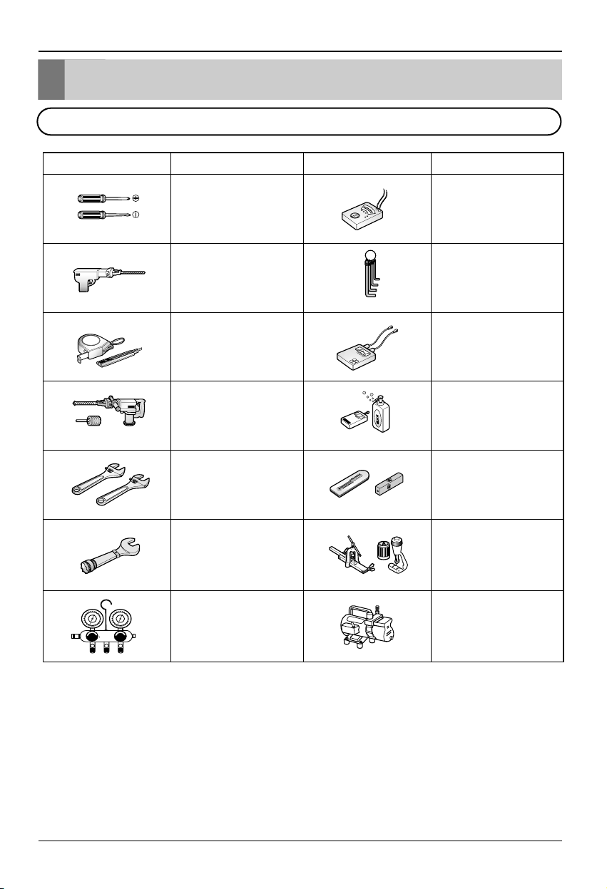
6) Preparation of installation parts and tools ...........................................................................................................12
7) Preparation of piping............................................................................................................................................13
8) Connection of piping ............................................................................................................................................14
9) Precautions in bending ........................................................................................................................................14
10) Connecting the cable to the indoor unit.............................................................................................................15
11) Connecting the piping to the outdoor unit..........................................................................................................16
12) Connecting the cable to the outdoor unit...........................................................................................................16
13) Power supply and wiring ....................................................................................................................................17
14) Vacuum drying of the connecting pipes and the indoor unit..............................................................................18
15) Form the pipe.....................................................................................................................................................19
Final Check and Test Run ...........................................................................................20
OUT-LINE OF INSTALLATION