LG SJ242CD User manual

SERVICE MANUAL
Room Air Conditioner
CAUTION
-BEFORE SERVICING THE UNIT, READ THE SAFETY
PRECAUTIONS IN THIS MANUAL.
-ONLY FOR AUTHORIZED SERVICE PERSONNEL.
WEBSITE http://biz.LGservice.com

Contents
3
4
Functions ................................................................................................................................
Product References ..............................................................................................................
Dimensions............................................................................................................................. 9
Refrigeration Cycle Diagram............................................................................................... 11
Wiring Diagram..................................................................................................................... 12
Operation Details ................................................................................................................. 14
Display Function .................................................................................................................. 21
Installation ............................................................................................................................ 22
Operation .............................................................................................................................. 33
Disassembly of the parts (Indoor Unit) .............................................................................. 34
2-way, 3-way Valve................................................................................................................ 36
Cycle Troubleshooting Guide.............................................................................................. 44
Electronic Parts Troubleshooting Guide............................................................................ 45
Electronic Control Device.................................................................................................... 52
Exploded View and Replacement Parts List...................................................................... 57
-2-

Functions
• Room temperature sensor. (THERMISTOR)
• Maintains the room temperature in accordance with the Setting Temp.
• Indoor fan is delayed for 5 sec at the starting.
• Restarting is inhibited for approx. 3 minutes.
• High, Med, Low, CHAOS
OUTDOOR---
Lights up in compressor operation (for Cooling Model)
• Intermittent operation of fan at low speed.
• The fan is switched to low(Cooling), med(Heating) speed.
• The unit will be stopped after 1, 2, 3, 4, 5, 6, 7 hours.
• The fan is switched to intermittent or irregular operation
•
The fan speed is automatically switched from high to low speed.
• The louver can be set at the desired position or swing
up and down automatically.
Indoor Unit
Operation ON/OFF by Remote controller
Sensing the Room Temperature
Room temperature control
Starting Current Control
Time Delay Safety Control
Indoor Fan Speed Control
Soft Dry Operation Mode
• The function will be operated while in any
operation mode with selecting the function.
• The function is to be stopped while it is
operating with selecting the function.
• Both the indoor and outdoor fan stops dur-
ing defrosting.
• The indoor fan stops until the
evaporator pipe temperature will be reached
at 28°C.
Sleep Mode Auto Control
Natural Air Control by CHAOS Logic
Airflow Direction Control
-3-
Defrost(Deice) control (Heating)
Hot-start Control (Heating)
PLASMA

Refrigeration Cycle Diagram
-4-
INDOOR UNIT OUTDOOR UNIT
HEAT
EXCHANGE
(EVAPORATOR)
HEAT
EXCHANGE
(EVAPORATOR)
HEAT
EXCHANGE
(CONDENSER)
HEAT
EXCHANGE
(CONDENSER)
COMPRESSOR
COMPRESSOR
ACCUMU
LATOR
GAS SIDE
GAS SIDE
VALVE
LIQUID SIDE
LIQUID SIDE
VALVE
CAPILLARY TUBE
CAPILLARY TUBE
CHECK VALVE
(Heating Model only)
COOLING
HEATING
REVERSING
VALVE
(Heating Model Only)
(1) Cooling Only Models
(2) Cooling & Heating Models

Operation Details
1. MAIN UNIT FUNCTION
• DISPLAY
1) C/O Model
Operation Indicator
• ON while in appliance operation, OFF while in appliance pause.
• Flashing while in disconnection or short in Thermistor. (3 sec off / 0.5 sec on)
Sleep Timer Indicator
• ON while in sleep timer mode, OFF when sleep timer cancel or appliance operation pause.
Timer Indicator
• ON while in timer mode (on/off), OFF when timer mode is completed or canceled.
Comp. Running Incidator
• While in appliance operation, ON while in outdoor unit compressor running, OFF while in compressor off.
2) H/P Model
Operation Indicator
• ON while in appliance operation, OFF while in appliance pause.
• Flashing while in disconnection or short in Thermistor. (3 sec off / 0.5 sec on)
Sleep Timer Indicator
• ON while in sleep timer mode, OFF when sleep timer cancel or appliance operation pause.
Timer Indicator
• ON while in timer mode (on/off), OFF when timer mode is completed or canceled.
Defrost Indicator
• OFF except when hot start during heating mode operation or while in defrost control.
■Cooling Mode Operation
• When the intak e air temper ature reaches 0.5 °C below the setting temp , the compressor and the outdoor f an
stop.
• When it reaches 0.5°C above the setting temp, they start to operate again.
Compressor ON Temp ➲ Setting Temp+0.5°C
Compressor OFF Temp ➲Setting Temp-0.5°C
• While in compressor r unning, operating with the airflo w speed set b y the remote control. While in compressor
not running, operating with the low airflow speed regardless of the setting.
■Healthy Dehumidification Mode
• When the dehumidification oper ation input b y the remote control is receiv ed, the intak e air temper ature is
detected and the setting temp is automatically set according to the intake air temperature.
26°C ≤Intake Air Temp ➲ 25°C
24°C ≤Intake Intake Air Temp<26°C ➲ Intake Air Temp-1°C
18°C ≤Intake Intake Air Temp<24°C ➲ Intake Air Temp-0.5°C
Intake Air Temp<18°C ➲ 18°C
-5-

• While in compressor off, the indoor fan repeats low airflow speed and pause.
• While the intak e air temp is betw een compressor on temp . and compressor off temp ., 10-min dehumidifica-
tion operation and 4-min compressor off repeat.
Compressor ON Temp. ➲Setting Temp+0.5°C
Compressor OFF Temp. ➲Setting Temp-0.5°C
• In 10-min dehumidification operation, the indoor fan operates with the low airflow speed.
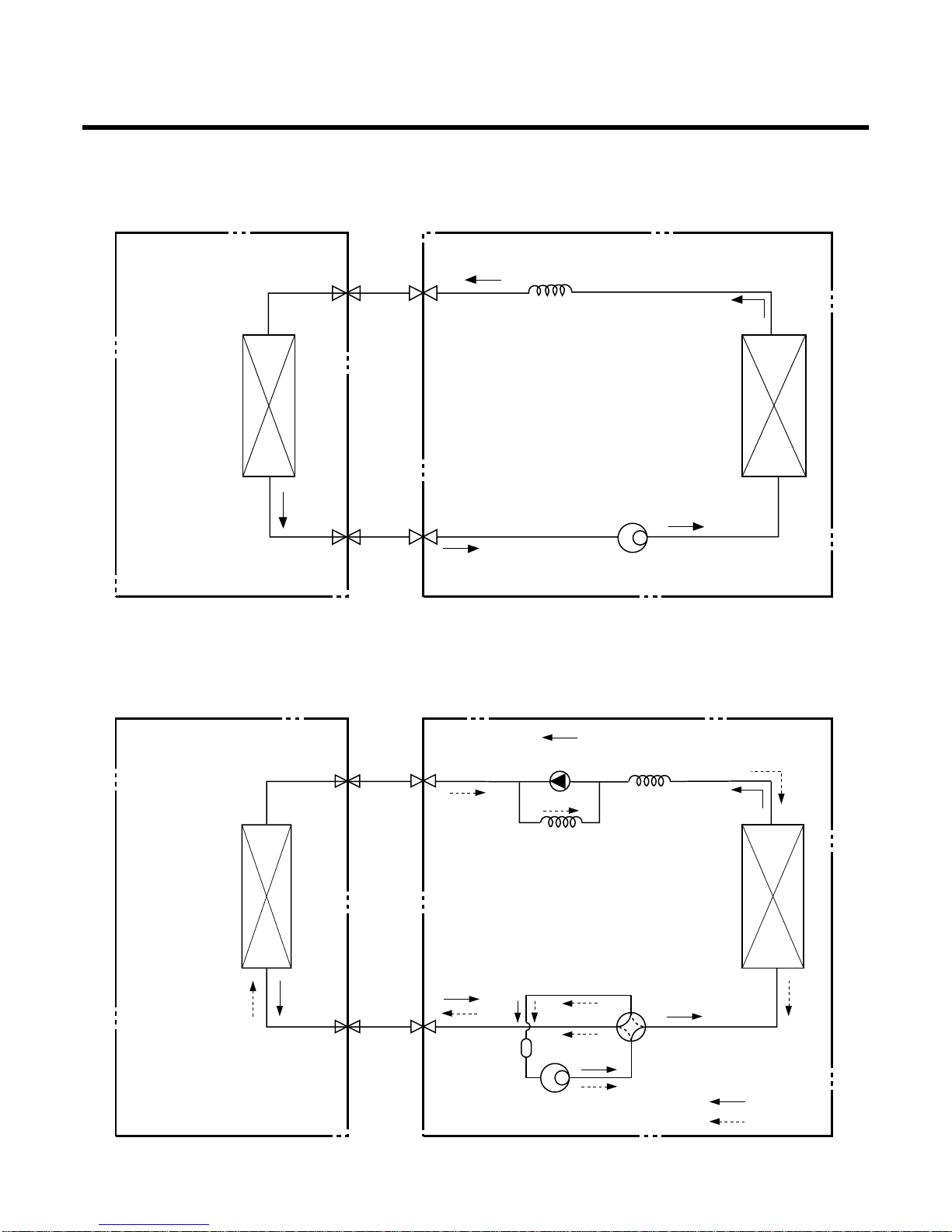
■Heating Mode Operation
• When the intak e air temp reaches +3 °…above the setting temp , the compressor is tur ned off. When belo w
the setting temp, the compressor is turned on.
Compressor ON Temp. ➲Setting Temp.
Compressor OFF Temp. ➲Setting Temp.+3°C
• While in compressor on, the indoor fan is off when the indoor pipe temp. is below 20°C, when above 28°C , it
operates with the low or setting airflow speed. When the indoor pipe temp is between 20°C and 28°C, it oper-
ates with Super-Low(while in sleep mode, with the medium airflow speed).
• While in compressor off, the indoor fan is off when the indoor pipe temp is belo w 33°C, when above 35°C , it
operates with the low airflow speed.
• If overloaded while in heating mode oper ation, in order to pre vent the compressor from OLP oper ation, the
outdoor fan is turned on/off according to the indoor pipe temp.
• While in defrost control, both of the indoor and outdoor fans are turned off.
■Defrost Control
• While in heating mode operation in order to protect the e vaporator pipe of the outdoor unit from freezing,
reversed to cooling cycle to defrost the evaporator pipe of the outdoor unit.
• After 40 min heating mode operation, at 4 min interval, whether to carry out defrost control or not and the time
of defrost control are determined according to the following conditions.
1) While in heating mode oper ation, the maxim um of the indoor pipe temper ature is measured and it is com-
pared with the present indoor pipe temper ature to get the diff erence of the indoor pipe temper atures (=the
maximum temperature of indoor pipe ? the present temper ature of indoor pipe), according to which, whether
to carry out defrost control or not is determined.
2) According to the need of defrost control shown above and the elapsed time of heating mode operation at that
moment, the defrost control time is determined.
3) When the determined time of defrost control is below 7 min, heating mode operation continues without carry-
ing out defrost control. According to the procedure stated abo ve, the determination is made again. When the
defrost control time is 7 min or longer, defrost control is then carried out.
• While in defrost control, the minimum temp of the indoor pipe is measured and it is compared with the present
temp of the indoor pipe to get the diff erence of the indoor pipe temper atures (=the present temper ature of the
indoor pipe ? the minimum temperature of the indoor pipe). When the difference is 5°C or higher, defrost con-
trol is completed and heating mode operation is carried out.
• While in defrost control, if the defrost time deter mined before the star t of defrost control is completed, defrost
control stops and heating mode operation is carried out regardless of the above condition.
• When the indoor pipe temp is 42 °C or abo ve, defrost control is not carr ied out even if the condition is one of
the defrost conditions above.
• While in defrost control, the compressor is on and the indoor fan, the outdoor fan, and the 4 way valve are off.
-6-

-7-
■ Fuzzy Operation (C/O Model)
• According to the temper ature set by Fuzzy r ule, when the intak e air temp is 0.5 °C or more belo w the setting
temp, the compressor is turned off. When 0.5°C or more above the setting temp, the compressor is turned on.
Compressor ON Temp ➲Setting Temp + 0.5°C
Compressor OFF Temp ➲Setting Temp + 0.5°C
• At the beginning of Fuzzy mode oper ation, the setting temper ature is automatically selected according to the
intake air temp at that time.
26°C ≤Intake Air Temp ➲25°C
24°C ≤Intake Air Temp < 26°C ➲Intake Air Temp + 1°C
22°C ≤Intake Air Temp < 24°C ➲Intake Air Temp + 0.5°C
18°C ≤Intake Air Temp < 22°C ➲Intake Air Temp
Intake Air Temp<18°C ➲ 18°C
• When the Fuzzy k ey (Temperature Control k ey) is input after the initial setting temper ature is selected, the
Fuzzy key value and the intak e air temper ature at that time are compared to select the setting temperature
automatically according to the Fuzzy rule.
• While in Fuzzy oper ation, the airflo w speed of the indoor f an is automatically selected according to the
temperature.
■Fuzzy Operation (H/P Model)
• When any of operation mode is not selected like the moment of the power on or when 3 hrs has passed since
the operation off, the operation mode is selected.
• When determining the operation mode, the compressor, the outdoor fan, and the 4 way valve are off and only
the indoor f an is oper ated for 15 seconds . Then an oper ation mode is selected according to the intak e air
temp at that moment as follows.
24°C ≤Inatake Air Temp ➲Fuzzy Operation for Cooling
21°C ≤Inatake Air Temp<24°C ➲Fuzzy Operation for Dehumidification
Inatake Air Temp<21°C ➲Fuzzy Operation for Heating
• If any of the operation modes among cooling / dehumidification / heating mode operations is carried out for 10
sec or longer before Fuzzy operation, the mode before Fuzzy operation is operated.
1) Fuzzy Operation for Cooling
• According to the setting temperature selected by Fuzzy rule, when the intake air temp is 0.5°C or more below
the setting temp, the compressor is tur ned off. When 0.5°C or more abo ve the setting temp, the compressor
is turned on.
Compressor ON Temp ➲Setting Temp +0.5°C
Compressor OFF Temp ➲Setting Temp + 0.5°C
• At the beginning of Fuzzy mode oper ation, the setting temper ature is automatically selected according to the
intake air temp at that time.
26°C≤Intake Air Temp ➲25°C
24°C≤Intake Air Temp<26°C ➲Intake Air Temp + 1°C
22°C≤Intake Air Temp<24°C ➲Intake Air Temp + 0.5°C
18°C≤Intake Air Temp<22°C ➲Intake Air Temp
Intake Air Temp<18°C ➲18°C
• When the Fuzzy k ey (Temperature Control k ey) is input after the initial setting temper ature is selected, the
Fuzzy key value and the intak e air temper ature at that time are compared to select the setting temperature
automatically according to the Fuzzy rule.
• While in Fuzzy oper ation, the airflo w speed of the indoor f an is automatically selected according to the tem-
perature.

-8-
2) Fuzzy Operation for Dehumidification
• According to the setting temper ature selected by Fuzzy rule, when the intake air temp is 0.5 °C or more below
the setting temp, the compressor is tur ned off. When 0.5 °C or more abo ve the setting temp, the compressor
is turned on.
Compressor ON Temp ➲Setting Temp + 0.5°C
Compressor OFF Temp ➲Setting Temp+0.5°C
• At the beginning of Fuzzy mode oper ation, the setting temper ature is automatically selected according to the
intake air temp at that time.
26°C ≤Intake Air Temp ➲25°C
24°C ≤Intake Air Temp<26°C ➲Intake Air Temp+1°C
22°C ≤Intake Air Temp<24°C ➲ Intake Air Temp+0.5°C
18°C ≤Intake Air Temp<22°C ➲Intake Air Temp
Intake Air Temp<18°C ➲18°C
• When the Fuzzy k ey (Temperature Control k ey) is input after the initial setting temper ature is selected, the
Fuzzy key value and the intak e air temper ature at that time are compared to select the setting temper ature
automatically according to the Fuzzy rule.
• While in Fuzzy oper ation, the airflo w speed of the indoor f an repeats the lo w airflow speed or pause as in
dehumidification operation.
3) Fuzzy Operation for Heating
• According to the setting temper ature selected b y Fuzzy r ule, when the intak e air temp is 3 °C or more abo ve
the setting temp, the compressor is turned off. When below the setting temp, the compressor is turned on.
Compressor ON Temp ➲Setting Temp
Compressor OFF Temp ➲Setting Temp + 3°C
• At the beginning of Fuzzy mode oper ation, the setting temper ature is automatically selected according to the
intake air temp at that time.
20°C≤Intake Air Temp ➲Intake Air Temp + 0.5°C
Intake Air Temp<20°C ➲20°C
• When the Fuzzy k ey (Temperature Control k ey) is input after the initial setting temper ature is selected, the
Fuzzy key value and the intak e air temper ature at that time are compared to select the setting temper ature
automatically according to the Fuzzy rule.
• While in Fuzzy operation, the airflow speed of the indoor fan is set to the high or the medium according to the
intake air temperature and the setting temperature.
■ Airflow Speed Selection
• The airflo w speed of the indoor f an is set to high, medium, lo w, or chaos (auto) b y the input of the airflo w
speed selection key on the remote control.
■On-Timer Operation
• When the set time is reached after the time is input by the remote control, the appliance starts to operate.
• The timer LED is on when the on-timer is input. It is off when the time set by the timer is reached.
• If the appliance is operating at the time set by the timer, the operation continues.

-9-
■ Off-Timer Operation
• When the set time is reached after the time is input by the remote control, the appliance stops operating.
• The timer LED is on when the off-timer is input. It is off when the time set by the timer is reached.
• If the appliance is on pause at the time set by the timer, the pause continues.
■ Off-Timer ↔On-Timer Operation
• When the set time is reached after the on/off time is input b y the remote control, the on/off-timer oper ation is
carried out according to the set time.
■ Sleep Timer Operation
• When the sleep time is reached after <1,2,3,4,5,6,7,0(cancel) hr> is input b y the remote control while in appli-
ance operation, the operation of the appliance stops.
• While the appliance is on pause, the sleep timer mode cannot be input.
• While in cooling mode oper ation, 30 min later since the star t of the sleep timer , the setting temper ature
increases by 1°C. After another 30 min elapse, it increases by 1°C again.
• When the sleep timer mode is input while in cooling cycle mode, the airflow speed of the indoor fan is set to the
low.
• When the sleep timer mode is input while in heating cycle mode , the airflo w speed of the indoor f an is set to
the medium.
■ Chaos Swing Mode
• By the Chaos Swing k ey input, the upper/lo wer vane automatically operates with the Chaos Swing or the y are
fixed to the desired direction.
• While in Chaos Swing mode, the angles of cooling and heating cycle operations are different.
■ Chaos Natural Wind Mode
• When the Chaos Natural Wind mode is selected and then oper ated, the high, medium, or low speed of the air-
flow mode is operated for 2~15 sec. randomly by the Chaos Simulation.
CLOSED
OPEN
< Cooling Mode >
7°
CLOSED
OPEN
< Heating Mode >
7°

-10-
■Forced Operation
• Operation procedures when the remote control can't be used.
• The operation will be started if the power button is pressed.
• If you want to stop operation, re-press the button.
• While in forced operation, the key input by the remote control has no effect and the buzzer sounds 10 times to
indicate the forced operation.
■Test operation
•
During the TEST OPERATION, the unit operates in cooling mode at high speed fan, regardless of room tem-
perature and resets in 18±1 minutes.
•
During test operation, if remote controller signal is received, the unit operates as remote controller sets.
If you want to use this operation, open the front panel upward and Press the power button let it be pressed for
about 3 seconds.
•
If you want to stop the operation, re-press the button.
■Auto restart
•
In case the power comes on again after a power failure, Auto Restarting Operation is the function to operate
procedures automatically to the previous operating conditions.
Heat pump Model
Cooling Model Room Temp. ≥24°C 21°C ≤Room Temp. < 24°C Room Temp. < 21°C
Operating mode Cooling Cooling Healthy Dehumidification Heating
Indoor FAN Speed
High High High High
Setting Temperature
22°C 22°C 23°C 24°C

-11-
■Remote Control Operation Mode
• When the remote control is selected b y the slide switch on the main unit, the appliance oper ates according to
the input by the remote control.
■Protection of the evaporator pipe from frosting
• If the indoor pipe temp is belo w 0°C in 7 min. after the compressor oper ates without any pause while in cool-
ing cycle oper ation mode, the compressor and the outdoor f an are tur ned off in order to protect the indoor
evaporator pipe from frosting.
• When the indoor pipe temp is 7 °C or higher after 3 min. pause of the compressor , the compressor and the
outdoor fan is turned on according to the condition of the room temperature.
■Buzzer Sounding Operation
• When the appliance-operation key is input by the remote control, the short "beep-beep-" sounds.
• When the appliance-pause key is input by the remote control, the long "beep—" sounds.
• When a k ey is input b y the remote control while the slide s witch on the main unit of the appliance is on the
forced operation position, the error sound "beep-beep-beep-beep-beep-" is made 10 times to indicate that the
remote control signal cannot be received.

Display Function
-12-
Self-diagnosis Function
3sec 3sec 3sec
(once)
Error
Code
1
Error Display LED
(Indoor body operation LED) Error contents
• Indoor room temperature
thermistor open/short
• Indoor pipe temperature
thermistor open/short.
• Indoor Thermistor
assembly check
SVC check point
1. Heating Model 2. Cooling Model
• Cooling, Soft Dry, Fan, Heating • Cooling, Soft Dry, Fan
• Sleep Mode • Sleep Mode
• Timer Mode • Timer Mode
• Hot-start, Defrost
Operation Indicator
Timer Indicator
Sleep Timer Indicator
Defrost Indicator
Operation Indicator
Timer Indicator
Sleep Timer Indicator
Compressor Indicator

1) Selection of the best location
1. Indoor unit
• Do not have any heat or steam near the unit.
• Select a place where there are no obstacles in front of
the unit.
• Make sure that condensation drainage can be conve-
niently routed away.
Do not install near a doorway.
• Ensure that the space around the left and right of the
unit is more than "A". The unit should be installed as
high on the wall as possible, allowing a minimum of
"B" from ceiling.
• Use a stud finder to locate studs to prevent unneces-
sary damage to the wall.
2. Outdoor unit
• If an awning is built over the unit to prevent direct sun-
light or rain exposure, make sure that heat radiation
from the condenser is not restricted.
• Ensure that the space around the back and sides is
more than 10cm. The front of the unit should have
more than 70cm of space.
• Do not place animals and plants in the path of the
warm air.
• Take the air conditioner weight into account and select
a place where noise and vibration are minimum.
• Select a place so that the warm air and noise from the
air conditioner do not disturb neighbors.
2) Piping length and elevation
Installation
1. Installation of indoor, Outdoor unit
-13-
More than "A"
More than "B"
More than 2.3m More than "B"
More than 10 cm
More than 10 cm
More than 70 cm
Install the indoor unit on the wall where the height
from the floors more than 2.3 meters.
CAUTION
• Capacity is based on standard length and maximum
allowance length is on the basis of reliability.
• Oil trap should be installed every 5~7 meters.
CAUTION
Grade Clearance(cm)
A B
7K~28K 10 5
30K~38K 30 12
Pipe Size
Capacity
(Btu/h) GAS LIQUID
Max.
Length
A(m)
Additional
Refrigerant
(g/m)
Max.
Elevation
B(m)
Standard
Length
(m)
7k~14k 3/8"(Ø9.52) 1/4"(Ø6.35) 4 or 7.5 7 15 20
1/2"(Ø12.7) 1/4"(Ø6.35) 4 or 7.5 7 15 20
1/2"(Ø12.7) 1/4"(Ø6.35) 4 or 7.5 15 30 20
18k~28k 5/8"(Ø15.88) 1/4"(Ø6.35) 4 or 7.5 15 30 20
5/8"(Ø15.88) 3/8"(Ø9.52) 4 or 7.5 15 30 30
30k~38k 5/8"(Ø15.88) 3/8"(Ø9.52) 7.5 15 30 30
3/4"(Ø19.05) 3/8"(Ø9.52) 7.5 15 30 50
If case more than 5m
Outdoor unit
Indoor unit
A
B
Outdoor unit
Indoor unit
A
B
A
Oil trap
Outdoor unit
Indoor unit
B
I

-14-
3) Drill a hole in the wall
• Drill the piping hole with a ø70mm hole core drill. Drill
the piping hole at either the right or the left with the
hole slightly slanted to the outdoor side.
mm7-5
)"61/5~"61/3(
Indoor
WALL
Outdoor

-15-
2. Flaring Work and Connection of Piping
1) Flaring work
Main cause for refrigerant leakage is due to defect in
the flaring work. Carry out correct flaring work using the
following procedure.
1. Cut the pipes and the cable.
•
Use the piping kit accessory or pipes purchased locally.
• Measure the distance between the indoor and the
outdoor unit.
• Cut the pipes a little longer than the measured
distance.
• Cut the cable 1.5m longer than the pipe length.
2. Burr removal
• Completely remove all burrs from the cut cross sec-
tion of pipe/tube.
• Put the end of the copper tube/pipe in a downward
direction as you remove burrs in order to avoid drop-
ping burrs into the tubing.
3. Putting nut on
• Remove flare nuts attached to indoor and outdoor
unit, then put them on pipe/tube having completed
burr removal.
(not possible to put them on after flaring work)
4. Flaring work
• Firmly hold copper pipe in a die in the dimension
shown in the table above.
• Carry out flaring work using flaring tool as shown
below.
5. Check
• Compare the flared work with figure below.
• If flare is noted to be defective, cut off the flared sec-
tion and re-flare it.
Copper
pipe
90°Slanted Uneven Rough
Bar
Copper pipe
Clamp handle Red arrow mark
Cone
Yoke
Handle
Bar
"A"
Inclined
Inside is shiny without scratches
Smooth all round
Even length
all round
Surface
damaged
Cracked Uneven
thickness
= Improper flaring =
Pipe
Reamer
Point down
Flare nut
Copper tube
mm inch mm
Ø6.35 1/4 0~0.5
Ø9.52 3/8 0~0.5
Ø12.7 1/2 0~0.5
Ø15.88 5/8 0~1.0
Ø19.05 3/4 1.0~1.3
Outside diameter

-16-
2) Connection of piping Indoor
• Preparing the indoor unit's piping and drain hose for
installation through the wall.
• Remove the plastic tubing retainer(see illustration
below) and pull the tubing and drain hose away from
chassis.
• Replace the plastic tubing holder in the original posi-
tion.
1. Route the indoor tubing and the drain hose in the
direction of rear right.
2. Insert the connecting cable into the indoor unit
from the outdoor unit through the piping hole.
• Do not connect the cable to the indoor unit.
• Make a small loop with the cable for easy
connection later.
3. Tape the tubing, drain hose, and the connecting
cable. Be sure that the drain hose is located at the
lowest side of the bundle. Locating at the upper
side can cause drain pan to overflow inside the
unit.
NOTE: If the drain hose is routed inside the room,
insulate the hose with an insulation material* so that
dripping from "sweating"(condensation) will not damage
furniture or floors.
*Foamed polyethylene or equivalent is recommended.
4. Indoor unit installation
• Hook the indoor unit onto the upper portion of the
installation plate.(Engage the two hooks of the rear
top of the indoor unit with the upper edge of the instal-
lation plate.) Ensure that the hooks are properly seat-
ed on the installation plate by moving it left and right.
Press the lower left and right sides of the unit against
the installation plate until the hooks engage into their
slots(clicking sound).
4. Connecting the pipings to the indoor unit and drain
hose to drain pipe.
• Align the center of the pipes and sufficiently tighten
the flare nut by hand.
For right rear piping
CAUTION
When install, mak e sure
that the remaining par ts
must be remo ved clear ly
so as not to damage the
piping and dr ain hose,
especially power cord
and connecting cable.
Tubing holder
Connecting
cable
Loop
Gas side
piping
Liquid side
piping
Drain hose
Drain hose
Connecting
cable
Indoor unit tubing Flare nut Pipes
Drain hose

-17-
• Tighten the flare nut with a wrench.
• When extending the drain hose at the indoor unit,
install the drain pipe.
5. Wrap the insulation material around the connecting
portion.
• Overlap the connection pipe insulation material and
the indoor unit pipe insulation material. Bind them
together with vinyl tape so that there is no gap.
•Wrap the area which accommodates the rear piping
housing section with vinyl tape.
• Bundle the piping and drain hose together by wrap-
ping them with vinyl tape for enough to cover where
they fit into the rear piping housing section.
1. Route the indoor tubing and the drain hose to the
required piping hole position.
2. Insert the piping, drain hose, and the connecting
cable into the piping hole.
For left rear piping
mm inch kg.m
Ø6.35 1/4 1.8
Ø9.52 3/8 4.2
Ø12.7 1/2 5.5
Ø15.88 5/8 6.6
Ø19.05 3/4 6.6
Outside diameter Torque
Wrench
Indoor unit tubing
Open-end wrench (fixed)
Connection pipe
Flare nut
Vinyl tape(narrow)
Adhesive
Drain pipe
Indoor unit drain hose
Plastic bands Insulation material
Vinyl tape(narrow)
Connection
pipe
Connecting cable
Vinyl tape
(wide) Wrap with vinyl tape
Indoor
unit pipe
Pipe
Wrap with vinyl tape
Drain hose
Pipe
Vinyl tape(wide)
Drain pipe
Connecting cable

-18-
3. Insert the connecting cable into the indoor unit.
• Don't connect the cable to the indoor unit.
•Make a small loop with the cable for easy connection
later.
4. Tape the drain hose and the connecting cable.
• Connecting cable
5. Indoor unit installation
• Hang the indoor unit from the hooks at the top of the
installation plate.
• Insert the spacer etc. between the indoor unit and the
installation plate and separate the bottom of the
indoor unit from the wall.
6. Connecting the pipings to the indoor unit and the
drain hose to drain pipe.
• Align the center of the pipes and sufficiently tighten
the flare nut by hand.
• Tighten the flare nut with a wrench.
• When extending the drain hose at the indoor unit,
install the drain pipe.
7. Wrap the insulation material around the con-
necting portion.
• Overlap the connection pipe heat insulation and the
indoor unit pipe heat insulation material. Bind them
together with vinyl tape so that there is no gap.
• Wrap the area which accommodates the rear piping
housing section with vinyl tape.
mm inch kg.m
Ø6.35 1/4 1.8
Ø9.52 3/8 4.2
Ø12.7 1/2 5.5
Ø15.88 5/8 6.6
Ø19.05 3/4 6.6
Outside diameter Torque
Vinyl tape
Adhesive
Drain hose
Indoor unit drain hose
(narrow)
Plastic bands Insulation material
Vinyl tape(narrow)
Connection
pipe
Connecting cable
Indoor
unit piping
Pipe
Vinyl tape
(wide) Wrap with vinyl tape
Installation plate
Spacer
Indoor unit
8cm
Indoor unit tubing Flare nut Pipes
Wrench
Indoor unit tubing
Connection pipe
Flare nut
Open-end wrench (fixed)

-19-
• Bundle the piping and drain hose together by wrap-
ping them with cloth tape over the range within which
they fit into the rear piping housing section.
8. Reroute the pipings and the drain hose across the
back of the chassis.
9. Set the pipings and the drain hose to the back of
the chassis with the tubing holder.
• Hook the edge of tubing holder to tap on chassis and
push the bottom of tubing holder to be engaged at the
bottom of chassis.
10. Indoor unit installation
• Remove the spacer.
• Ensure that the hooks are properly seated on the
installation plate by moving it left and right.
Press the lower left and right sides of the unit against
the installation plate until the hooks engage into their
slots(clicking sound).
3) Connection of the pipes-Outdoor
1. Align the center of the pipings and sufficiently
tighten the flare nut by hand.
2. Finally, tighten the flare nut with torque wrench
until the wrench clicks.
• When tightening the flare nut with torque wrench,
ensure the direction for tightening follows the arrow on
the wrench.
mm inch kg.m
Ø6.35 1/4 1.8
Ø9.52 3/8 4.2
Ø12.7 1/2 5.5
Ø15.88 5/8 6.6
Ø19.05 3/4 6.6
Outside diameter Torque
Drain hose
Vinyl tape(narrow)
Pipe
Wrap with
vinyl tape(wide)
Piping for
passage through
piping hole
Outdoor unit
Gas side piping
(Bigger diameter)
Liquid side
piping
(Smaller
diameter)
Torque wrench
Tubing holder
Drain hose
Connecting
cable

-20-
3. Connecting The Cable Between Indoor Unit and Outdoor Unit
1) Connect the cable to the Indoor unit.
• Connect the cable to the indoor unit by connecting the wires to the terminals on the control board in
dividually according to the outdoor unit connection. (Ensure that the color of the wires of the outdoor unit and
the terminal No. are the same as those of the indoor unit.)
The earth wire should be longer than the common wires.
Air
Conditioner
Main power source
If a power plug is not to be used, provide a circuit breaker
between power source and the unit as shown below.
Circuit Breaker
Use a circuit
breaker or time
delay fuse.
CAUTION
CAUTION
The power cord connected to the "A" unit should be
complied with the following specifications
(Type "B" approved by HAR or SAA).
Grade
5k~9K 12k~14k 18k 24k~28k 30k, 32k 36k, 38k
0.75 1.0 1.5 2.5 2.5 5.5
Unit(A) Indoor Indoor Indoor Indoor Outdoor Outdoor
Cable Type(B)
H05VV-F H05VV-F H05VV-F H05VV-F H05RN-F H05RN-F
NORMAL
CROSS
-SECTIONAL
AREA
5k~9k 12k~14k 18k 24k~28k
0.75 1.0 1.5 2.5
Cable Type(B) H07RN-F H07RN-F H07RN-F H07RN-F
NORMAL
CROSS
-SECTIONAL
AREA
Grade
30k, 32k 36k, 38k
0.75 0.75
Cable Type(B) H07RN-F H07RN-F
NORMAL CROSS
-SECTIONAL AREA
Grade
(mm2)
(mm2)
(mm2)
The power connecting cable connected to the indoor
and outdoor unit should be complied with the following
specifications
(Type "B" approved by HAR or SAA).
NORMAL
CROSS-SECTIONAL
AREA 0.75mm2
• The above circuit diagram is subject to change with-
out notice.
• Be sure to connect wires according to the wiring dia-
gram.
• Connect the wires firmly, so that not to be pulled out
easily.
• Connect the wires according to color codes by refer-
ring the wiring diagram.
CAUTION
• When installing, refer to the circuit diagram on the
Control Box of Indoor Unit.
• When installing, refer to the wiring diagram on the
Control Cover Inside Outdoor Unit.
Table of contents
Other LG Air Conditioner manuals
Popular Air Conditioner manuals by other brands

Mitsubishi Electric
Mitsubishi Electric MSC-GE20VB operating instructions

Mitsubishi Electric
Mitsubishi Electric PUZ-ZM200YKA2-ET Service manual

EcoNet
EcoNet A2024AJVCA installation instructions

Hisense
Hisense 7K Use and Installation Instructions

Admiral
Admiral AW-05CM1FLU use and care manual

Panasonic
Panasonic CU-E9GFE-2 operating instructions

Samsung
Samsung AR18NSWSPWKXCV Service manual

Sharp
Sharp AU-1802Y Operation manual

QuietCool
QuietCool QC18DVS owner's manual

Mitsubishi Electric
Mitsubishi Electric Mr.Slim MS-GK36VA operating instructions

Mitsubishi Electric
Mitsubishi Electric City Multi Series Technical & service manual

Toshiba
Toshiba RAS-10J2KV-HK owner's manual