LG LB8000ER User manual

ENGLISH ESPAÑOL
LG
Window-Type Air Conditioner
OWNER'S MANUAL
LG
MODELS: LB8000ER,LW8000ER
PRECAUTIONS
www.lgservice.com
IMPORTANT
• Please read this owner's manual carefully and thoroughly
before installing and operating your room air conditioner.
• Please retain this owner's manual for future reference after
reading it thoroughly.
• Antes de instalar y poner en marcha su ventilador de
casa, haga el favor de leer cuidadosamente esta
instrucción de Usuario.
• Luego de su lectura, guarde este manual para el futuro
usuario para las referencias.

2
Window-Type Air Conditioner Owner’s Manual
TABLE OF CONTENTS
1. Safety Precautions
2. Operating Instructions
3. Care and Maintenance
4. Hardware Installation
5. Common Issues
FOR YOUR RECORDS
Write the model and serial numbers here:
Model #
Serial #
You can find them on a label on the side of each unit.
Dealer's Name
Date Purchased
■Staple your receipt to this page in the event you need
it to prove date of purchase or for warranty issues.
READ THIS MANUAL
Inside you will find many helpful hints on how to use
and maintain your air conditioner properly. Just a little
preventive care on your part can save you a great deal
of time and money over the life of your air conditioner.
You'll find many answers to common problems in the
chart of troubleshooting tips. If you review our chart of
Troubleshooting Tips first, you may not need to call
for service at all.
PRECAUTION
•Contact the authorized service technician for repair or
maintenance of this unit.
• Contact the installer for installation of this unit.
• The air conditioner is not intended for use by young
children or invalids without supervision.
• Young children should be supervised to ensure that
they do not play with the air conditioner.
• When the power cord is to be replaced, replacement
work shall be performed by authorized personnel only
using only genuine replacement parts.
• Installation work must be performed in accordance with
the National Electric Code by qualified and authorized
personnel only.

3
ENGLISH
Precautions
Safety
Precautions
To prevent injury to the user or other people and property damage, the following instructions must
be followed.
■Incorrect operation due to ignoring instruction will cause harm or damage. The seriousness is
classified by the following indications.
WARNING
CAUTION
This symbol indicates the possibility of death or serious injury.
This symbol indicates the possibility of injury or damage to properties only.
■Meanings of symbols used in this manual are as shown below.
Be sure not to do.
Be sure to follow the instruction.
WARNING
■Installation
Always install the expansion panel(s).
• No installation may cause fire and electric
shock accident.
Do not place the power cord near a heater.
• It may cause fire and electric shock.
Do not use the power cord near flammable
gas or combustibles such as gasoline,
benzene, thinner, etc.
• It may cause explosion or fire.
Do not disassemble or modify products.
• It may cause failure and electric shock.
Gasolin

4
■Operation
Plug in the power plug
properly.
• Otherwise, it will cause
electric shock or fire due to
heat generation or electric
shock.
Do not operate or stop the
unit by inserting or pulling
out the power plug.
• It will cause electric shock or
fire due to heat generation.
Do not damage or use an
unspecified power cord.
• It will cause electric shock or
fire.
Do not modify power cord
length.
• It will cause electric shock or
fire due to heat generation.
Do not share the outlet with
other appliances.
• It will cause electric shock or
fire due to heat generation.
Always plug into a
grounded outlet.
• No grounding may cause
electric shock (See
Installation Manual).
Unplug the unit if strange
sounds, odors, or smoke
come from it.
• Otherwise it may cause fire
and electric shock accident.
Do not use the socket if it is
loose or damaged.
• It may cause fire and electric
shock.
Do not operate with wet
hands or in damp
environment.
• It will cause electric shock.
ON
ON

5
ENGLISH
Do not allow water to run
into electric parts.
• It will cause failure of machine
or electric shock.
Leave the door closed while
the air conditioner is
running.
• It is not designed to cool the
entire house.
Ventilate before operating
air conditioner when gas
goes out.
• It may cause explosion, fire,
and burn.
Never touch the metal parts
of the unit when removing
the filter.
• They are sharp and may
cause injury.
Do not block the inlet or
outlet.
• It may cause failure of
appliance or accident.
Ensure that the outer case
is not damaged by age or
wear.
• If leaving appliance damaged,
there is concern of damage
due to the falling of product.
Be cautious not to touch the
sharp edges when
installing.
• It may cause injury.
Hold the plug by the head
when taking it out.
• It may cause electric shock
and damage.
Turn off the main power
switch when not using it for
a long time.
• Prevent accidental startup
and the possibility of injury.
CAUTION
■Installation
Sharp
edges
■Operation

6
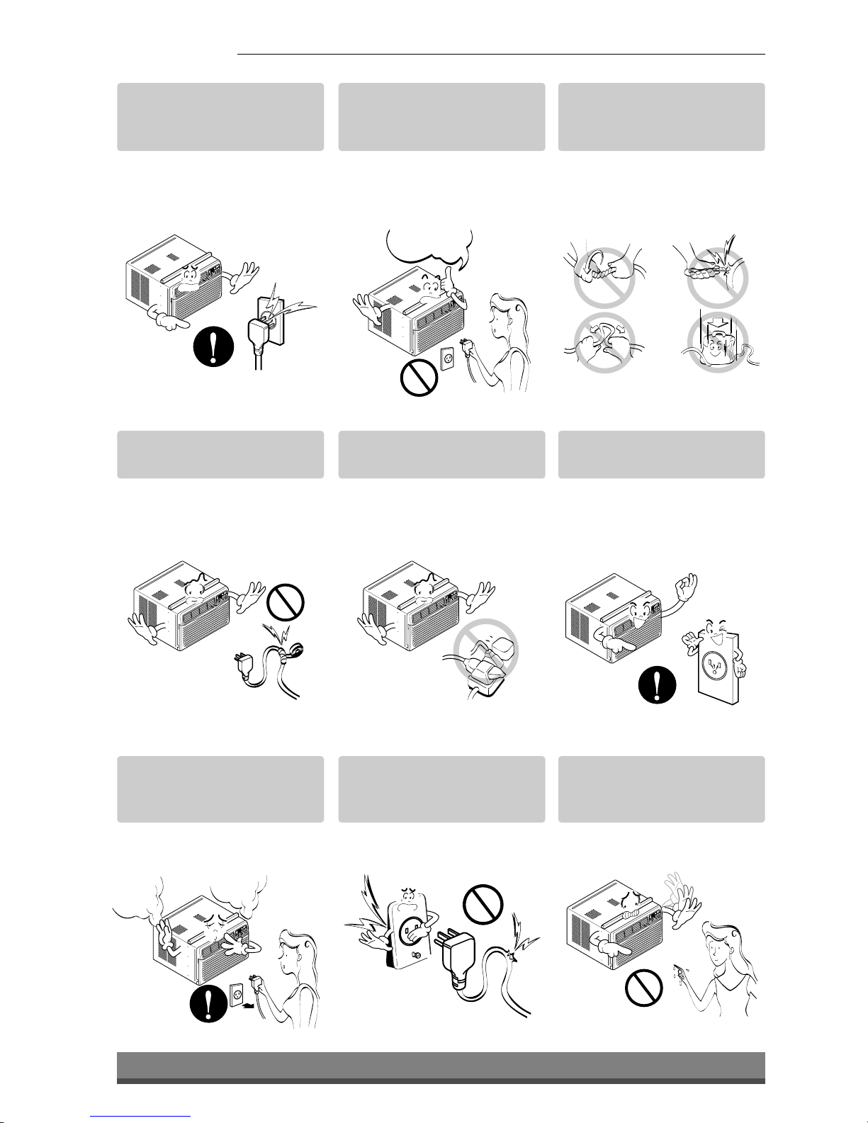
Do not place heavy object
on the power cord and take
care so that the cord should
not be pressed.
•There is danger of fire or
electric shock.
If water enters the product,
turn off the the power switch
of the main body of appliance.
Contact service center after
taking the power-plug out
from the socket.
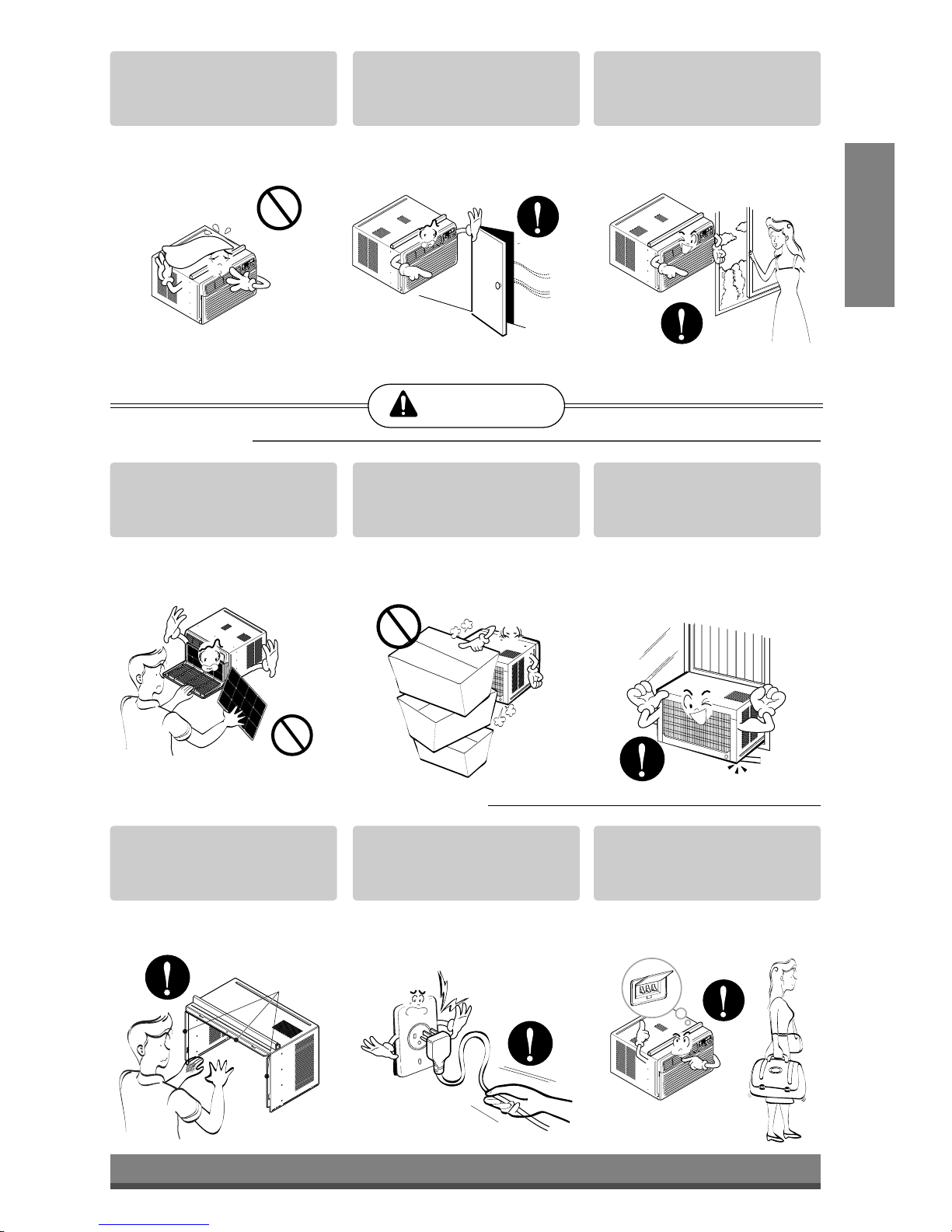
Do not clean the air
conditioner with water.
•Water may enter the unit and
degrade the insulation. It may
cause an electric shock.
Turn off the power and
breaker firstly when
cleansing the unit.
•Since the fan rotates at high
speed during operation, it
may cause injury.
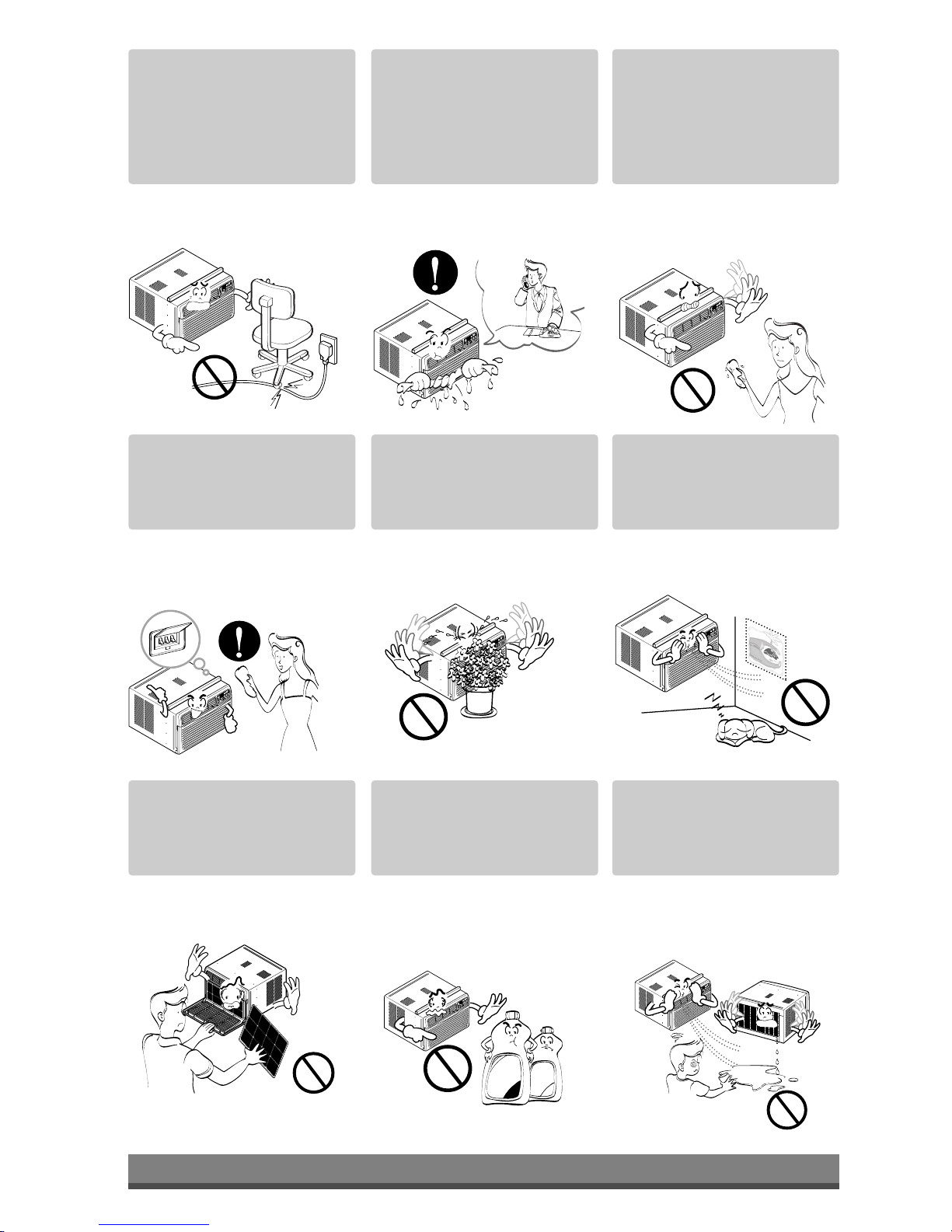
Do not put a pet or house
plant where it will be
exposed to direct air flow.
•This could injure the pet or
plant.
Do not use this appliance
for special purposes such
as pets, foods, precision
machinery, or objects of art.
•It is an air conditioner, not a
precision refrigeration system.
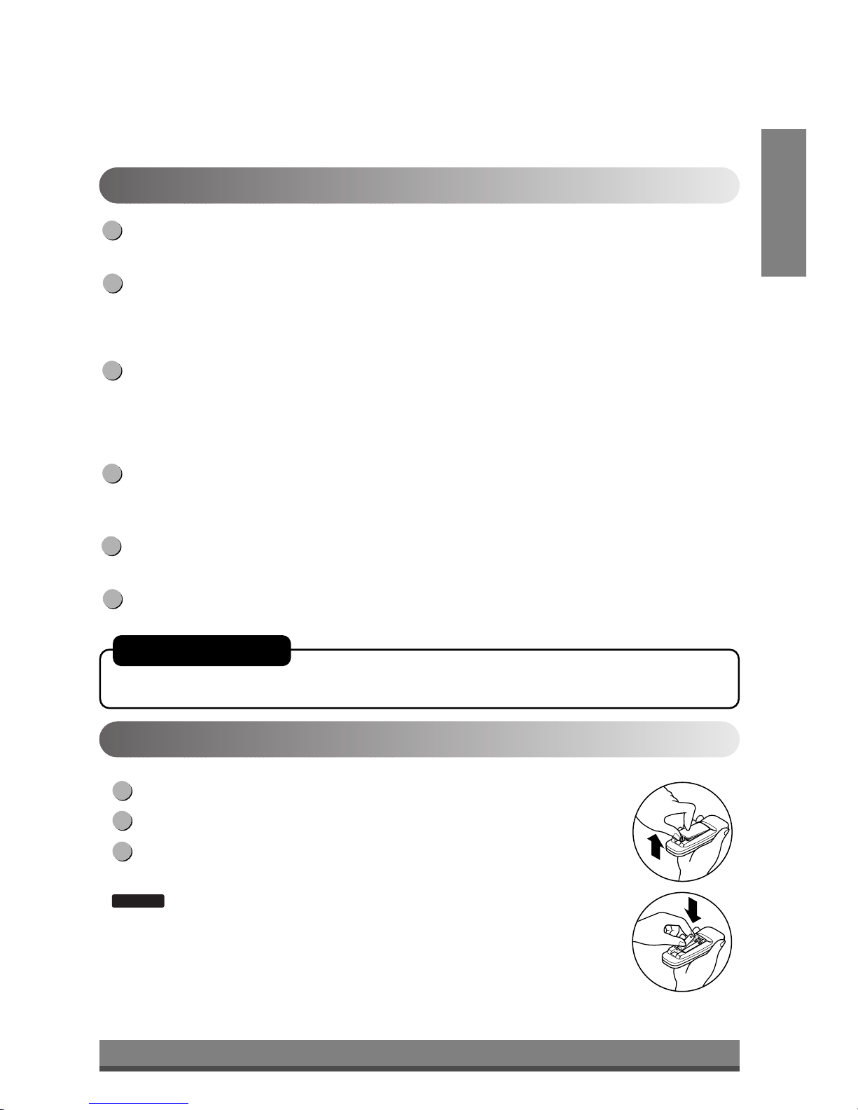
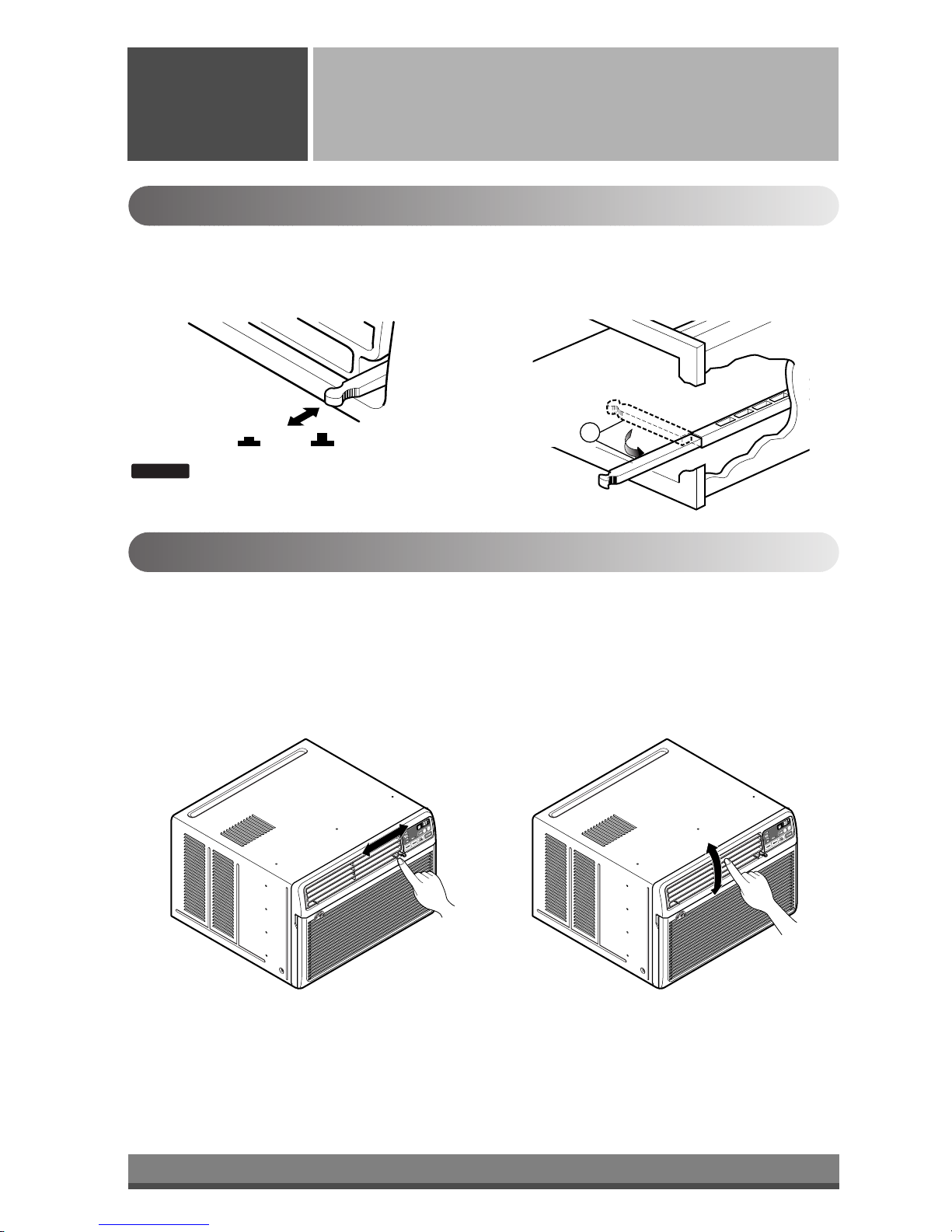
Always insert the filter
securely.
Clean it every two weeks.
•Operation without filters will
cause failure.
Use a soft cloth to clean. Do
not use wax, thinner, or a
strong detergent.
•The appearance of the air
conditioner may deteriorate,
change color, or develop
surface flaws.
Do not drink water drained
from air conditioner. / Do
not direct airflow at room
occupants only.
•It contains containments and
will make you sick. / This
could damage your health.
•It will cause electric shock
or failure of machine.
Wax
Thinner

TITLE 1
SECTION
7
ENGLISH
Prior to Operation
Safety
Precautions
Preparing for operation
Contact an installation specialist for installation.
Plug in the power plug properly.
Do not share the same outlet with other appliances
Do not use an extension cord.
Do not start/stop operation by plugging/unplugging the power cord.
If cord/plug is damaged, replace only with an authorized part.
6
5
4
3
2
1
Usage
Cleaning and maintenance
Do not use water to clean inside the air conditioner. Exposure to water can destroy the insulation, leading
to possible electric shock.
When cleaning the unit, first make sure that the power and breaker are turned off. The fan rotates at a
very high speed during operation. There is a possibility of injury if the unit’s power is accidentally
triggered on while cleaning inner parts of the unit.
2
1
Service
For repair and maintenance, contact your authorized service dealer.
Being exposed to direct airflow for an extended period of time could be hazardous to your health. Do not
expose occupants, pets, or plants to direct airflow for extended periods of time.
Due to the possibility of oxygen deficiency, ventilate the room when using together with stoves or other
heating devices.
Do not use this air conditioner for non-specified special purposes (e.g. preserving precision devices,
food, pets, plants, and art objects). Usage in such a manner could harm such property.
3
2
1

8
Power
Temp
Fan Speed
Timer Mode
1
2
3
4
5
'
F
TIMER POWERMODE
TEMP
FAN
SPEED
F1 LOW
F2 MED
F3 HIGH
Dry Timer
Fan
Energy
Saver
Cool
1
2
6
3 45
Remote Control Operations
Operating
Instructions
The remote control and control panel will look like those represented in the following pictures.

9
ENGLISH
Push out the cover on the back of the remote control with your thumb
Pay attention to polarity and insert two new AAA 1.5V batteries.
Reattach the cover.
: Do not use rechargeable batteries. Make sure that both batteries are new.
•In order to prevent discharge, remove the batteries from the remote control if the air
conditioner is not going to be used for an extended period of time
Keep the remote control away from extremely hot or humid places.
To maintain optimal operation of the remote control, the remote sensor should not be
exposed to direct sunlight.
•The remote control can be mounted on a wall using the mountable holder.
NOTICE
3
2
1
Inserting the Remote Control Batteries
POWER
Operation starts when this button is pressed and stops when you press the button again.
TEMPERATURE CONTROL
The thermostat monitors room temperature to maintain the desired temperature.
The thermostat can be set between 60°F~86°F (16°C~30°C).
The unit takes an average of 30 minutes to adjust the room temperature by 1°F.
OPERATION MODE SELECTOR
Select cooling mode to cool the room.
Select energy saver mode for energy saving operation.
Select fan mode for basic ventilating fan operation.
Select dry mode for dry operation.
FAN SPEED SELECTOR
For increased power while cooling, select a higher fan speed.
3 steps: High ➔Low ➔Med
ON/OFF TIMER
The timer can be set to start and stop the unit in hourly increments (up to 12 hours).
REMOTE CONTROL SENSOR
6
5
4
3
2
1
Remote Control OperationsRemote Control Operations
AUTO RESTART
In failure of electric power, the unit runs as previous setting operation.

10
OPEN
VENTCLOSE Part A
Adjusting the Air Flow Direction
Operating
Instructions
Vent Control
For maximum cooling efficiency, CLOSE the vent. This will allow internal air circulation.
OPEN the vent to discharge stale air.
Adjusting the Air Flow Direction
•Recommended orientation of louvers
Adjust louvers to face upwards when cooling to maximize cooling efficiency.
Airflow can be adjusted by changing the direction of the air conditioner's louvers. This can also increase the
cooling efficiency of the air conditioner.
:Before using the ventilation feature, position
the vent lever straight by pulling Part A out
and snapping it into place.
NOTICE
Adjusting horizontal air flow Adjusting vertical air flow
•Adjusting Horizontal Air Flow Direction
Adjusting the vertical louvers left and right will
change horizontal airflow.
•Adjusting Vertical Air Flow Direction
Adjusting the horizontal vane up and down will
change vertical airflow. The vane can be adjusted
by nudging the vane backward or forward.

11
ENGLISH
Drain pipe
Drain cap
Care and Maintenance
Care and
Maintenance
Turn the power off and unplug the power plug before cleaning the air conditioner.
Air Filter
The air filter behind the inlet grille should be checked and cleaned at least once every 2 weeks (or as
necessary) to maintain optimal performance of the air conditioner.
How to remove the air filter
The grille may be opened from the top for easy
maintenance after installation.
Open the inlet grille by pulling off the exposed door
on the top of the unit (based on installation).
Pull the tab slightly to release the filter. Pull the filter
in the same direction as the opening.
Clean the filter with warm, soapy water. The water
should be below 40°C (104°F).
Rinse off and gently shake off excess water from the
filter. Let it dry before replaceing it.
5
4
3
2
1
Drainage
The base pan may overflow due to high humidity. To drain the excess
water, remove the drain cap from the back of the unit and secure the
drainpipe.
When pressing the drainpipe into place, apply force in the direction
away from the fins to avoid injuring yourself.

TITLE 1
SECTION
12
4
1
2
3
13
11
14
12
7
10
B
A
6
5
8
15
9
Power Cord
Power Cord
Hardware Installation
Hardware
Installation
Product Features
1. CABINET
2. FRONT GRILLE
3. AIR FILTER
4. AIR INTAKE (INLET GRILLE)
5. AIR DISCHARGE
6. VERTICAL AIR DEFLECTOR
(HORIZONTAL LOUVER)
7. EVAPORATOR
8. HORIZONTAL AIR DEFLECTOR
(VERTICAL LOUVER)
9. CONTROL PANEL
10. POWER CORD
11. COMPRESSOR
12. BASE PAN
13. BRACE
14. CONDENSER
15. REMOTE CONTROLLER
Installing the Power cord
You can choose between two methods below according to your window stool shape and preference.
•Fasten the stopper using 2 screw holes, and lead
out the power cord through slit "A".
•Fasten the stopper using left screw hole, and rotate
properly to lead the power cord out through slit "B".
Using slit "A" Using slit "B"
CAUTION: This appliance should be installed in accordance with national wiring
regulations. The following information serves acts as a guide to help to explain product
features.

13
About 1/2"
30"~60"
Awning
Cooled air
Fence
Over 20"
Heat
radiation
23" to 36"
15" min.
Inner sill Offset
Window
Sash
Sill
Exterior
Interior wall
20 1/12" min.
(Without frame curtain)
How to Install the Unit
To prevent vibration and noise, make sure the unit
is installed securely and firmly.
Install the unit where the sunlight does not shine
directly on the unit.
There should be no obstacles, such as a fence and
wall, within 20" from the back of the cabinet
because it will prevent heat radiation of the
condenser.
Restriction of outside air will greatly reduce the
cooling efficiency of the air conditioner.
Install the unit a little slanted so the back is slightly lower than the front (about 1/2").
This will force condensed water to flow to the outside.
Install the unit with the bottom about 30"~60" above the floor level.
5
4
3
2
1
Window Requirements
:All supporting parts should be secured to firm wood, masonry, or metal.
•This unit is designed for installation in standard double
hung windows with actual opening widths from 23"
to 36".
•The top and bottom window sash must open sufficiently
to allow a clear vertical opening of 15" from the bottom
of the upper sash to the window stool.
NOTICE
CAUTION: All side louvers of the cabinet must remain exposed to the outside of the
structure.
ENGLISH

14
12 3 4
8 13
10
765
9
12
1114
9
10
13
Shipping
Screws
(Type A)
(Type A)
5
11
11
9
5
5
Installation Kits Contents
Suggested Tool Requirements
NO. NAME OF PARTS Q'TY
1 FRAME CURTAIN 2
2 SILL SUPPORT 2
3 BOLT 2
4 NUT 2
5 SCREW (TYPE A) 16
6 SCREW (TYPE B) 3
7 SCREW (TYPE C) 5
8 FOAM-STRIP 1
9 UPPER GUIDE 1
10 FOAM-PE 1
11 FRAME GUIDE 2
12 WINDOW LOCKING BRACKET 1
13 FOAM-PE 1
14 DRAIN PIPE 1
PREPARATION OF CHASSIS
Remove the screws which fasten the cabinet at both
sides and at the back.
Slide the unit from the cabinet by gripping the base pan
handle and pulling forward while bracing the cabinet.
Cut the window sash seal to the proper length.
Peel off the backing and attach the Foam-PE to the
underside of the window sash.
Remove the backing from the top upper guide Foam-PE
and attach it to the bottom of the Upper Guide .
Attach the upper guide onto the top of the cabinet with 3
Type A screws .
Insert the Frame Guides into the bottom of the
cabinet.
Insert the Frame Curtain into the Upper Guide and
Frame Guides .
Fasten the curtains to the unit with 4 Type
A screws .
8
7
6
5
4
3
2
1
SCREWDRIVER(Philips and Flatead), RULER, KNIFE, HAMMER, PENCIL, LEVEL

15
ENGLISH
Cabinet Installation
Open the window. Mark a line on center of the
window stool.
Carefully place the cabinet on the window stool and
align the center mark on the bottom front with the
center line marked in the window stool.
Pull the bottom window sash down behind the Upper
Guide until it meets.
NOTE: Do not pull the window sash down tightly that the
movement of Frame Curtain is restricted.
Loosely assemble the Sill Support using the parts
in Fig. 3.
Select the position that will place the Sill Support
near the outer most point on sill (See Fig. 4)
NOTE: Be careful when you install the cabinet (Frame
Guides are broken easily).
Attach the Sill Support to the cabinet track hole in
relation to the selected position using 2 Type A
screws in each support (See Fig. 4).
5
4
3
2
1
INDOOR OUTDOOR
Sill Support
2
Nut
4
Bolt
3
INDOOR OUTDOOR
Cabinet
About 1/2"
Frame Guide
11
Screw(Type A)
5
Upper Guide Window stool
Front Angle
Window Sash Upper guide
9
Frame Curtain
1
Foam-pe
10
Foam-pe
13
Cabinet
Fig. 1
Fig. 2
Fig. 3
Fig. 4

16
Sash track
Front Angle
About 1/2"
Screw(Type B)
6
Screw(Type B)
6
Sill Support
2
Sill Support
2
Foam-Strip
8
Fig. 5
Type C
7
Fig. 6
Screw(Type A)
Screw
(Type A)
Power cord Fig. 7
Fig. 8
The cabinet should be installed with a very slight tilt
(about 1/2") downward toward the outside
(See Fig. 5).
Adjust the bolt and the nut of Sill Support for
balancing the cabinet.
Attach the cabinet to the window stool by driving
the screws (Type B: Length 16mm (5/8 inch)
and below.) through the front angle into window
stool.
Pull each Frame Curtain fully to each window
sash track, and repeat step 2.
Attach each Frame Curtain the window sash using
screws (Type C). (See Fig. 6)
CAUTION: Do not drill a hole in the bottom pan.
The unit is designed to operate with
approximately 1/2" of water in bottom pan.
There is no need to add water if the pan is dry.
Slide the unit into the cabinet. (See Fig. 7)
CAUTION: For security purpose, reinstall screws (Type A)
at cabinet's sides.
Cut the Foam-Strip to the proper length and insert
between the upper window sash and the lower
window sash. (See Fig. 8)
11
10
9
8
7
6

17
ENGLISH
Window locking
bracket
12
Do not under any
circumstances cut
or remove the
grounding prong
from the plug.
Line Cord Plug Use Wall Receptacle Power Supply
Power supply cord with
3-prong grounding plug Standard 125V, 3-wire grounding
receptacle rated 15A, 125V AC
Use 15 AMP, time
delay fuse or circuit
breaker.
Fig. 9
Fig. 10
Fig. 11
Attach the Window Locking Bracket with a Type
C screw . (See Fig. 9)
Attach the front grille to the cabinet by inserting the
tabs on the grille into the tabs on the front of the
cabinet. Push the grille in until it snaps into place.
(See Fig. 10)
Pull down the inlet grille and secure it with a Type
A screw through the front grille. (See Fig. 11)
Window installation of room air conditioner is
now completed. See ELECTRICAL DATA for
attaching power cord to electrical outlet.
15
14
13
12
Electrical Data
Use of extension cords
•Because of potential safety hazards, we strongly discourage the use of an extension cord. However, if you wish
to use an extension cord, use a CSA certified/UL-listed 3-wire (grounding) extension cord, rated at 15A, 125V.

18
PREFERRED METHOD
Ensure proper ground
exists before use
TEMPORARY METHOD
Adapter plug
Receptacle cover
Metal screw
Fig. 12
Fig. 13
Electrical Safety
IMPORTANT
(PLEASE READ CAREFULLY)
FOR THE USER'S PERSONAL SAFETY, THIS
APPLIANCE MUST BE PROPERLY GROUNDED
The power cord of this appliance is equipped with a
three-prong (grounding) plug. Use this with a standard
three-slot (grounding) wall power outlet (Fig. 12) to
minimize the hazard of electric shock. The customer
should have the wall receptacle and circuit checked by
a qualified electrician to make sure the receptacle is
properly grounded.
DO NOT CUT OR REMOVE THE THIRD (GROUND)
PRONG FROM THE POWER PLUG.
A. SITUATIONS WHEN THE APPLIANCE WILL BE
DISCONNECTED OCCASIONALLY:
Because of potential safety hazards, we strongly
discourage the use of an adapter plug. However, if you
wish to use an adapter, a TEMPORARY
CONNECTION may be made. Use UL-listed adapter,
available from most local hardware stores (Fig. 13).
The large slot in the adapter must be aligned with the
large slot in the receptacle to assure a proper polarity
connection.
CAUTION: Attaching the adapter ground terminal to
the wall receptacle cover screw does not
ground the appliance unless the cover
screw is metal, and not insulated, and the
wall receptacle is grounded through the
house wiring. The customer should have
the circuit checked by a qualified electrician
to make sure the receptacle is properly
grounded.
Disconnect the power cord from the adapter, using one
hand on each. Otherwise, the adapter ground terminal
might break. DO NOT USE the appliance with a
broken adapter plug.
B. SITUATIONS WHEN THE APPLIANCE WILL BE
DISCONNECTED OFTEN.
Do not use an adapter plug in these situations.
Unplugging the power cord frequently can lead to an
eventual breakage of the ground terminal. The wall
power outlet should be replaced by a three-slot
(grounding) outlet instead.
USE OF EXTENSION CORDS
Because of potential safety hazards, we strongly
discourage the use of an extension cord. However, if
you wish to use an extension cord, use a CSA
certified/UL-listed 3-wire (grounding) extension cord,
rated at 15A, 125V.

19
Common Problems and Solutions
Common
Issues
Before calling for service, please review the following list of common problems and solutions.
The air conditioner is operating normally when:
•You hear a pinging noise. This is caused by water being picked up by the condenser on rainy days or in highly
humid conditions. This feature is designed to help remove moisture in the air and improve cooling efficiency.
•You hear the thermostat click. This is caused by the compressor cycle starting and stopping.
•You see water dripping from the rear of the unit. Water may be collected in the base pan in highly humid
conditions or on rainy days. This water overflows and drips from the rear of the unit.
•You hear the fan running while the compressor is silent. This is a normal operational feature.
The air conditioner may be operating abnormally when:
Problem Possible Causes What To Do
■The air conditioner is unplugged or
not plugged in completely
■The fuse is blown/circuit breaker is
triggered
■Power failure.
■Air flow is restricted
■The THERMOSTAT may not be
set cool enough
■The air filter is dirty.
■The air conditioner was just
turned on.
■Cold air is escaping.
■Cooling coils are iced up
■The cooling coils are iced over.
•Make sure the plug is completely plugged into
the outlet
•Check the fuse/circuit breaker box and replace
the fuse or reset the breaker
•In the event of a power failure, set the power
control to OFF. When the power is restored,
wait 3 minutes to restart the air conditioner to
prevent the compressor from overloading
•Make sure there are no curtains, blinds,
furniture or other obstacles in front of the air
conditioner
•Turn the knob to a higher setting. The highest
setting provides maximum cooling
•Clean the filter at least every 2 weeks. Refer to
the “Care and Maintenance”section (p.11) of
the manual.
•After the air conditioner is turned on, you need
to give the air conditioner some time to cool the
room.
•Check for open furnace floor resisters and cold
air returns.
•CLOSE the air conditioner vent
•See Ice appears on the air conditioner below
•Ice may block the air flow and obstruct the air
conditioner from properly cooling the room. Set
the fan at MED or HIGH while setting the
thermostat at 1 or 2 until the ice melts.
The air conditioner
does not operate
at all
Air conditioner
does not cool
Ice appears on the
air conditioner.
ENGLISH

20
Memo
Other manuals for LB8000ER
1
This manual suits for next models
2
Table of contents
Languages:
Other LG Air Conditioner manuals
Popular Air Conditioner manuals by other brands

Fujitsu
Fujitsu AJ**A72LBTF Installation instruction sheet

Panasonic
Panasonic CS-PS9PKV-7 operating instructions

EINHELL
EINHELL MKA 2500 E operating instructions

Mitsubishi Electric
Mitsubishi Electric Mr. SLIM PKA-M LA 2 Series installation manual

Trotec
Trotec PAC 4600 Supplemental sheet

Haier
Haier HSU-12HT03 Operation manual

Olimpia splendid
Olimpia splendid DOLCECLIMA AIR PRO 14AC Instructions for use and maintenance

Daewoo
Daewoo COL1579 user manual

Toshiba
Toshiba R410A Service manual

Samsung
Samsung FH18BTA(X) Service manual

Hitachi
Hitachi R32/R410A Series Installation & operation manual

Haier
Haier HWR10XC6 - annexe 1 manual