—3—
LP 12 0 C E M 1
12 34 5 6 7 8 9
Digits 1,2 - LG Packaged Terminal Air Conditioner Digit 6 - Product Type
Digits 3,4 - Unit Cooling Capacity C = Air Conditoner
07 = 7,000 Btu/h H = Heat Pump
09 = 9,000 Btu/h Digit 7- Electric Heat
12 = 12,000 Btu/h E = Electric Heater
15 = 15,000 Btu/h Digit 8 - D = Digital
M = Mechanical
Digit 9 - Electric Voltage
1 = 265V, 60Hz
None = 230V, 60Hz
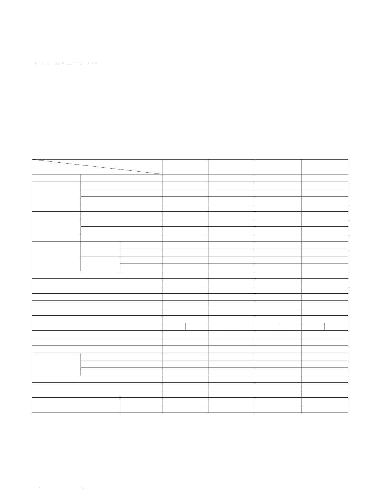
1.1 SPECIFICATIONS
MODELS
ITEMS
POWER SUPPLY
COOLING CAPACITY (Bru/h)
INPUT (W)
RUNNING CURRENT (A)
E.E.R. (Btu/h.W)
HEATING CAPACITY (Bru/h)
INPUT (W)
RUNNING CURRENT (A)
COP(W/W)
OPERATING COOLING INDOOR (°C)
TEMPERATURE OUTDOOR (°C)
HEATING INDOOR (°C)
OUTDOOR (°C)
REFRIGEANT(R-22) CHARGE(g)
EVAPORATOR
CONDENSER
FAN, INDOOR
FAN, OUTDOOR
FAN SPEEDS (FAN/COOLING/HEATING)
FAN MOTOR
OPERATION CONTROL
ROOM TEMP. CONTROL
CONSTRUCTION
ELECTRIC HEATER
PROTECTOR COMPRESSOR
FAN MOTOR
ELECTRIC HEATER
POWER CORD
DRAIN SYSTEM
NETWEIGHT(lbs/Kg)
DIMENSION (W*H*D) (inch)
(mm)
LP090CED LP120CED LP150CED LP070HED
1Ø, 230/208V, 60Hz 1Ø, 230/208V, 60Hz 1Ø, 230/208V, 60Hz 1Ø, 230/208V, 60Hz
9,000/8,800 11,800/11,500 14,300/14,100 7,600/7,300
770/750 1,055/1,025 1,430/1,410 600/575
3.5/3.8 4.8/5.2 6.5/7.1 2.7/2.9
11.7/11.7 11.2/11.2 10.0/10.0 12.7/12.7
- - - 6,400/6,200
---535/520
- - - 2.4/2.6
- - - 3.5/3.5
26.7 (DB) 19.4(WB) 26.7 (DB) 19.4(WB) 26.7 (DB) 19.4(WB) 26.7 (DB) 19.4(WB)
35 (DB) 23.9(WB) 35 (DB) 23.9(WB) 35 (DB) 23.9(WB) 35 (DB) 23.9(WB)
21.1 (DB) 15.6(WB) 21.1 (DB) 15.6(WB) 21.1 (DB) 15.6(WB) 21.1 (DB) 15.6(WB)
8.3 (DB) 6.1(WB) 8.3 (DB) 6.1(WB) 8.3 (DB) 6.1(WB) 8.3 (DB) 6.1(WB)
790(27.9 OZ) 630(22.2 OZ) 735(25.9 OZ) 610(21.5 OZ)
2 ROE 10 STACKS 2 ROE 10 STACKS 2 ROE 10 STACKS 2 ROE 12 STACKS
2 ROE 14 STACKS 2 ROE 17 STACKS 2 ROE 17 STACKS 2 ROE 17 STACKS
Cross Flow Fan Cross Flow Fan Cross Flow Fan Cross Flow Fan
Axial Fan Axial Fan Axial Fan Axial Fan
2/2/2 2/2/2 2/2/2 2/2/2
4POLES 4POLES 4POLES 4POLES
MANUAL TYPE MANUAL TYPE MANUAL TYPE MANUAL TYPE
THERMISTOR THERMISTOR THERMISTOR THERMISTOR
SLID IN-OUT SLID IN-OUT SLID IN-OUT SLID IN-OUT
3.5KW, 230V 3.5KW, 230V 3.5KW, 230V 2.5KW, 230V
EXTERNAL OVERLOAD PROTECTOR EXTERNAL OVERLOAD PROTECTOR EXTERNAL OVERLOAD PROTECTOR EXTERNAL OVERLOAD PROTECTOR
INTERNAL THERMAL PROTECTOR INTERNAL THERMAL PROTECTOR INTERNAL THERMAL PROTECTOR INTERNAL THERMAL PROTECTOR
FUSE LINK, BIMETAL THERMOSTAT FUSE LINK, BIMETAL THERMOSTAT FUSE LINK, BIMETAL THERMOSTAT FUSE LINK, BIMETAL THERMOSTAT
1.6m(3 WIRE WITH GROUDING) 1.6m(3 WIRE WITH GROUDING) 1.6m(3 WIRE WITH GROUDING) 1.6m(3 WIRE WITH GROUDING)
SPLASHED BY FAN SLINGER SPLASHED BY FAN SLINGER SPLASHED BY FAN SLINGER SPLASHED BY FAN SLINGER
92/42.8 96/43.7 101/45.7 90/40.7
41 31/32*15 31/32*19 27/32 41 31/32*15 31/32*19 27/32 41 31/32*15 31/32*19 27/32 41 31/32*15 31/32*19 27/32
1066*406*505 1066*406*505 1066*406*505 1066*406*505


 null")