manuals.online logo
Brands
  1. Home
  2. •
  3. Brands
  4. •
  5. LG
  6. •
  7. Heat Pump
  8. •
  9. LG LS091HSV3 User manual

LG LS091HSV3 User manual

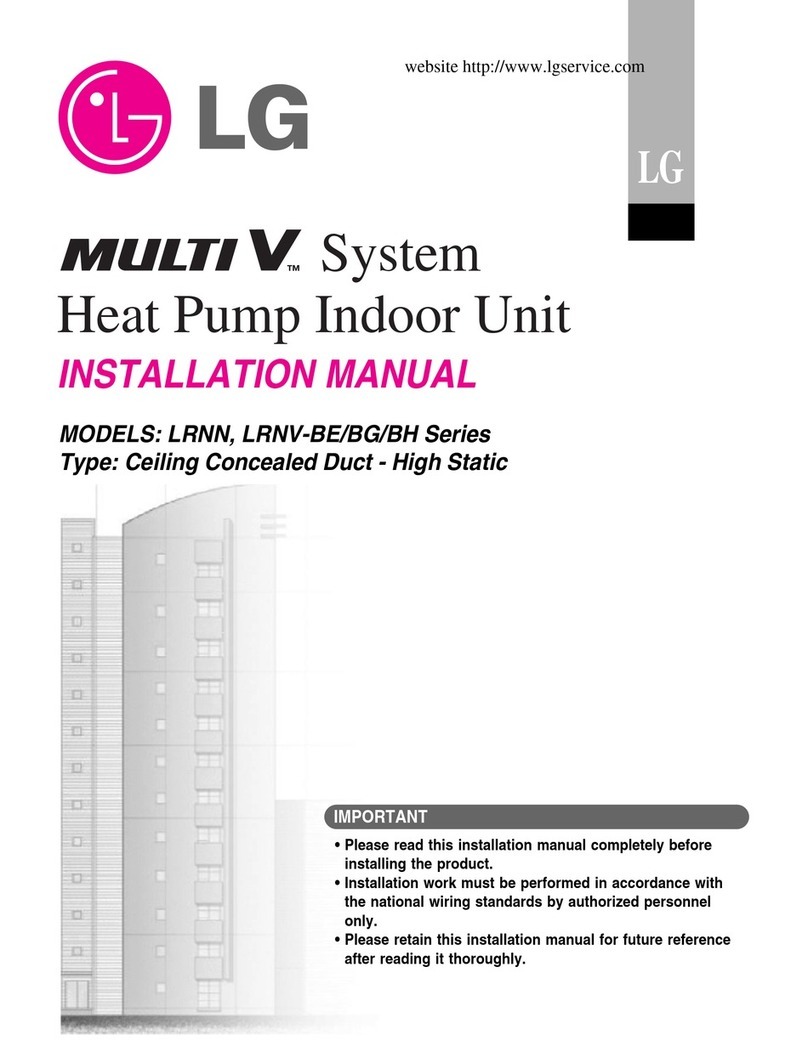
SINGLE ZONE HIGH EFFICIENCY, STANDARD,
EXTENDED PIPE, AND MEGA WALL MOUNTED
INSTALLATION MANUAL
6LQJOH=RQH+LJK(I¿FLHQF\
LS091HSV3, LS121HSV3, LS181HSV3, LS240HSV3
SLQJOH =RQH SWDQGDUG LS30HV3, LS30HV3
SLQJOH =RQH ([WHQGHG 3LSH LS240HLV, LS300HLV, LS30HLV
SLQJOH =RQH 0HJD LS090H(V, LS120H(V, LS180H(V, LS240H(V
LS090HEV1, LS120HEV1, LS180HEV1, LS240HEV1
SLQJOH =RQH 0HJD 11VLS090H;V, LS120H;V
The instructions included in this manual must be followed to prevent product malfunction, property damage, injury, or death to the user or
other people. Incorrect operation due to ignoring any instructions will cause harm or damage. The level of seriousness is classified by the
symbols described below.
'R QRW WKURZ DZD\, GHVWUR\, RU ORVH WKLV PDQXDO
Please read carefully and store in a safe place for future reference.
Content familiarity required for proper installation.
A summary list of safety precautions begins on page 3.
)RU PRUH WHFKQLFDO PDWHULDOV VXFK DV VXEPLWWDOV, HQJLQHHULQJ
GDWDERRNV, DQG FDWDORJV, YLVLW ZZZOJKYDFFRP
For continual product development, LG Electronics U.S.A., Inc., reserves the right to change specifications without notice.
©LG Electronics U.S.A., Inc.
This document, as well as all reports, illustrations, data, information, and other materials are the property of LG Electronics U.S.A., Inc.
PROPRIETARY DATA NOTICE
This document, as well as all reports, illustrations, data, information, and
other materials are the property of LG Electronics U.S.A., Inc., and are
disclosed by LG Electronics U.S.A., Inc., only in confidence.
This document is for design purposes only.
IM_WallMounted_All_11_15
3
Safety Instructions
Due to our policy of continuous product innovation, some specifications may change without notification.
©LG Electronics U.S.A., Inc., Englewood Cliffs, NJ. All rights reserved. “LG” is a registered trademark of LG Corp.
SAFETY INSTRUCTIONS
The instructions below must be followed to prevent product malfunction, property damage, injury or death to the user or other people. Incor-
rect operation due to ignoring any instructions will cause harm or damage. The level of seriousness is classified by the symbols described
below.
TABLE OF SYMBOLS
Do not install, remove, or re-install the unit by yourself
(end user). Ask the dealer or an authorized technician to
install the unit.
Improper installation Ey the user may result in water leaNaJe, ¿re,
explosion, electric shock, physical injury or death.
For replacement of an installed unit, always contact an LG
trained service provider.
There is risk of ¿re, electric shock, explosion, and physical injury or death.
The unit is shipped with refrigerant and the service valves
closed. Do not open service valves on the unit until all
non-condensibles have been removed from the piping sys-
tem and authorization to do so has been obtained from the
commissioning agent.
There is a risk of physical injury or death.
Do not run the compressor with the service valves
closed.
There is a risk of explosion, physical injury, or death.
Periodically check that the outdoor frame is not damaged.
There is a risk of explosion, physical injury, or death.
Replace all control box and panel covers.
If cover panels are not installed securely, dust, water and animals may
enter the unit, causinJ¿re, electric shock, and physical injury or death.
Always check for system refrigerant leaks after the unit has
been installed or serviced.
Exposure to high concentration levels of refrigerant gas may lead to ill-
ness or death.
Wear protective gloves when handling equipment. Sharp
edges may cause personal injury.
Dispose the packing materials safely.
• Packing materials, such as nails and other metal or wooden parts,
may cause puncture wounds or other injuries.
• Tear apart and throw away plastic packaging bags so that children
may not play with them and risk suffocation and death.
Install the unit considering the potential for strong winds or
earthquakes.
Improper installation may cause the unit to fall over, resulting in physical
injury or death.
Do not change the settings of the protection devices.
If the pressure switch, thermal switch, or other protection device is
shorted and forced to operate improperly, or parts other than those
speci¿ed by LG are used, there is risk of ¿re, electric shock, explosion,
and physical injury or death.
Do not install the unit on a defective stand.
There is a risk of physical injury.
INSTALLATION
'RQ¶WVWRUHRUXVHÀDPPDEOHJDVFRPEXVWLEOHVQHDUWKH
unit.
There is risk of ¿re, explosion, and physical injury or death.
This symbol indicates an imminently hazardous situation which, if not avoided, will result in death or serious injury.
This symbol indicates a potentially hazardous situation which, if not avoided, could result in death or serious injury.
This symbol indicates a potentially hazardous situation which, if not avoided, may result in minor or moderate injury.
This symbol indicates situations that may result in equipment or property damage accidents only.
This symbol indicates an action should not be completed.
DANGER
CAUTION
4
6LQJOH=RQH+LJK(I¿FLHQF\6WDQGDUG([WHQGHG3LSHDQG0HJD:DOO0RXQW,QVWDOODWLRQ0DQXDO
Due to our policy of continuous product innovation, some specifications may change without notification.
©LG Electronics U.S.A., Inc., Englewood Cliffs, NJ. All rights reserved. “LG” is a registered trademark of LG Corp.
SAFETY INSTRUCTIONS
INSTALLATION - CONTINUED
Don’t install the unit where it’s directly exposed to ocean
winds.
Ocean winds may cause corrosion, particularly on the condenser and
evaporator ¿ns, which, in turn could cause product malfunction or inef-
¿cient performance.
When installing the unit in a low-lying area, or a location that
is not level, use a raised concrete pad or concrete blocks to
provide a solid, level foundation.
This may prevent water damage and reduce abnormal vibration.
Properly insulate all cold surfaces to prevent “sweating.”
Cold surfaces such as uninsulated piping can generate condensate that may
drip and cause a slippery surface condition and/or water damage to walls.
When installing the unit in a hospital, mechanical room, or
VLPLODUHOHFWURPDJQHWLF¿HOG(0)VHQVLWLYHHQYLURQPHQW
SURYLGHVXI¿FLHQWSURWHFWLRQDJDLQVWHOHFWULFDOQRLVH
Inverter equipment, power generators, high-frequency medical equip-
ment, or radio communication equipment may cause the air conditioner to
operate improperly. The unit may also affect such equipment by creating
electrical noise that disturbs medical treatment or image broadcasting.
Do not use the product for special purposes such as
preserving foods, works of art, wine coolers, or other
precision air conditioning applications. The equipment is
designed to provide comfort cooling and heating.
There is risk of property damage.
Do not make refrigerant substitutions. Use R410A only.
If a different refrigerant is used, or air mixes with original refrigerant, the
unit will malfunction and be damaged.
Keep the unit upright during installation to avoid vibration or
water leakage.
Do not install the unit in a noise sensitive area.
When connecting refrigerant tubing, remember to allow for
pipe expansion.
Improper piping may cause refrigerant leaks and system malfunction.
Take appropriate actions at the end of HVAC equipment life
to recover, recycle, reclaim or destroy R410A refrigerant
according to applicable U.S. Environmental Protection
Agency (EPA) rules.
Periodically check that the outdoor frame is not damaged.
There is a risk of equipment damage.
Install the unit in a safe location where nobody can step on
or fall onto it. Do not install the unit on a defective stand.
There is risk of unit and property damage.
Install the drain hose to ensure adequate drainage.
There is a risk of water leakage and property damage.
'RQ¶WVWRUHRUXVHÀDPPDEOHJDVFRPEXVWLEOHVQHDUWKH
unit.
There is risk of product failure.
Always check for system refrigerant leaks after the unit has
been installed or serviced.
Low refrigerant levels may cause product failure
The unit is shipped with refrigerant and the service valves
closed. Do not open service valves on the unit until all
non-condensibles have been removed from the piping system
and authorization to do so has been obtained from the com-
missioning agent.
There is a risk of refrigerant contamination, refrigerant loss and equip-
ment damage.
Do not run the compressor with the service valves
closed.
There is a risk of equipment damage.
Be very careful when transporting the product.
•Do not attempt to carry the product without assistance.
• Some products use polypropylene bands for packaging. Do not
use polypropylene bands to lift the unit.
• Suspend the unit from the base at specified positions.
• Support the unit a minimum of four points to avoid slippage from
rigging apparatus.
If the air conditioner is installed in a small space, take
measures to prevent the refrigerant concentration from
exceeding safety limits in the event of a refrigerant leak.
Consult the latest edition of ASHRAE (American Society of Heating,
Refrigerating, and Air Conditioning Engineers) Standard 15. If the
refrigerant leaks and safety limits are exceeded, it could result in personal
injuries or death from oxygen depletion.
Install the unit in a safe location where nobody can step on or
fall onto it.
There is risk of physical injury or death.
Properly insulate all cold surfaces to prevent “sweating.”
Cold surfaces such as uninsulated piping can generate condensate that
could drip, causing a slippery surface that creates a risk of slipping, falling,
and personal injury.
5
Safety Instructions
Due to our policy of continuous product innovation, some specifications may change without notification.
©LG Electronics U.S.A., Inc., Englewood Cliffs, NJ. All rights reserved. “LG” is a registered trademark of LG Corp.
SAFETY INSTRUCTIONS
High voltage electricity is required to operate this system.
Adhere to the National Electrical Codes and these
instructions when wiring.
Improper connections and inadequate grounding can cause accidental
injury or death.
Always ground the unit following local, state, and National
Electrical Codes.
Turn the power off at the nearest disconnect before servicing
the equipment.
Electrical shock can cause physical injury or death.
Properly size all circuit breakers or fuses.
There is risk of ¿re, electric shock, explosion, physical injury or death.
WIRING
The information contained in this manual is intended for use
E\DQLQGXVWU\TXDOL¿HGH[SHULHQFHGFHUWL¿HGHOHFWULFLDQ
familiar with the U.S. National Electric Code (NEC) who is
equipped with the proper tools and test instruments.
Failure to carefully read and follow all instructions in this manual can
result in equipment malfunction, property damage, personal injury or death.
All electric work must be performed by a licensed electrician
and conform to local building codes or, in the absence of
local codes, with the National Electrical Code, and the
instructions given in this manual.
If the power source capacity is inadequate or the electric work is not per-
formed properly, it may result in ¿re, electric shock, physical injury or death.
Refer to local, state, and federal codes, and use power wires
RIVXI¿FLHQWFXUUHQWFDSDFLW\DQGUDWLQJ
:ires that are too small may generate heat and cause a ¿re.
6HFXUHDOO¿HOGZLULQJFRQQHFWLRQVZLWKDSSURSULDWHZLUH
strain relief.
Improperly securing wires will create undue stress on equipment power
lugs. Inadequate connections may generate heat, cause a ¿re and phys-
ical injury or death.

6LQJOH=RQH+LJK(I¿FLHQF\6WDQGDUG([WHQGHG3LSHDQG0HJD:DOO0RXQW,QVWDOODWLRQ0DQXDO
Due to our policy of continuous product innovation, some specifications may change without notification.
©LG Electronics U.S.A., Inc., Englewood Cliffs, NJ. All rights reserved. “LG” is a registered trademark of LG Corp.
SAFETY INSTRUCTIONS
&OHDQXSWKHVLWHDIWHULQVWDOODWLRQLV¿QLVKHGDQGFKHFN
that no metal scraps, screws, or bits of wiring have been left
inside or surrounding the unit.
Do not use this equipment in mission critical or special-
purpose applications such as preserving foods, works of art,
wine coolers or refrigeration. The equipment is designed to
provide comfort cooling and heating.
Oil, steam, sulfuric smoke, etc., can signi¿cantly reduce the performance
of the unit, or damage its parts.
Provide power to the compressor crankcase heaters at least
six (6) hours before operation begins.
Starting operation with a cold compressor sump(s) may result in severe
bearing damage to the compressor(s). Keep the power switch on during
the operational season.
Do not block the inlet or outlet.
Unit may malfunction.
Securely attach the electrical part cover to the indoor unit
and the service panel to the outdoor unit.
Non-secured covers can result in malfunction due to dust or water in the
service panel.
Periodically verify the equipment mounts have not
deteriorated.
If the base collapses, the unit could fall and cause property damage
or product failure.
Do not allow water, dirt, or animals to enter the unit.
There is risk of unit failure.
OPERATION
'RQRWSURYLGHSRZHUWRRURSHUDWHWKHXQLWLILWLVÀRRG-
ed or submerged.
There is risk of ¿re, electric shock, physical injury or death.
Use a dedicated power source for this product.
There is risk of ¿re, electric shock, physical injury or death.
Do not operate the disconnect switch with wet hands.
There is risk of ¿re, electric shock, physical injury or death.
If gas leaks out, ventilate the area before operating the unit.
If the unit is mounted in an enclosed, low-lying, or poorly ventilated area,
and the system develops a refrigerant leak, it may cause ¿re electric
shock, explosion, physical injury or death.
To avoid physical injury, use caution when cleaning or
servicing the air conditioner.
Do not allow water, dirt, or animals to enter the unit.
There is risk of ¿re, electric shock, physical injury or death.
Avoid excessive cooling and periodically perform ventilation
to the unit.
Inadequate ventilation is a health hazard.
Do not touch the refrigerant piping during or after oper-
ation.
It can cause burns or frostbite.
Do not operate the unit with the panel(s) or protective
FRYHUVUHPRYHGNHHS¿QJHUVDQGFORWKLQJDZD\IURP
moving parts.
The rotating, hot, cold, and high-voltage parts of the unit can cause
physical injury or death.
Periodically verify the equipment mounts have not
deteriorated.
If the base collapses, the unit could fall and cause physical injury or death.
Periodically, check power cord and plug for damage.
Cord must be replaced by the manufacturer, its service agent, or similar
quali¿ed persons in order to avoid physical injury and/or electric shock.
Do not open the inlet grille of the unit during operation.
Do not operate the unit with the panels or guards re-
moved. Do not insert hands or other objects through the
inlet or outlet when the unit is plugged in. Do not touch
WKHHOHFWURVWDWLF¿OWHULIWKHXQLWLQFOXGHVRQH
The unit contains sharp, rotating, hot, and high voltage parts that can
cause personal injury and/or electric shock.
Securely attach the electrical part cover to the indoor unit
and the service panel to the outdoor unit.
Non-secured covers can result in burns or electric shock due to dust or
water in the service panel.

Due to our policy of continuous product innovation, some specifications may change without notification.
©LG Electronics U.S.A., Inc., Englewood Cliffs, NJ. All rights reserved. “LG” is a registered trademark of LG Corp.
TABLE OF CONTENTS
Safety Instructions................................................................................3
General Data..........................................................................................8
Unit Nomenclature............................................................................... 8
Single =one High Ef¿ciency Unit Speci¿cations.................................. 9
Single =one Standard Unit Speci¿cations ......................................... 10
Single =one Extended Pipe Unit Speci¿cations .................................11
Single =one 0ega Unit Speci¿cations.......................................... 12-13
Single =one 0ega 1159Unit Speci¿cations...................................... 14
Electrical............................................................................................ 15
R410A Refrigerant............................................................................. 16
General Installation Guidelines..........................................................17
Location Selection ............................................................................. 17
Oceanside Applications ..................................................................... 18
Mounting Bolt Location...................................................................... 19
Required Clearances.................................................................... 19-20
Mounting of Indoor Unit Installation Plate..................................... 21-25
Mounting of Indoor Unit ..................................................................... 26
Piping Preparation............................................................................. 27
Piping Materials and Handling...................................................... 28-33
Piping Support, Elbow Usage............................................................ 33
Refrigerant Piping System Layout..................................................... 35
Refrigerant Piping Connections.........................................................36
Refrigerant Piping System Limitations............................................... 36
Installation Overview ......................................................................... 38
Directional Pipe Formation ................................................................ 39
Drain Hose......................................................................................... 40
Outdoor Unit Connections ............................................................ 41-42
Indoor Unit Connections.................................................................... 43
Indoor Unit Connections - Conduit Bracket Placement ..................... 44
Bundling and Cutting Line ................................................................. 45
Refrigerant Piping Insulation ........................................................ 46-48
Air Purging......................................................................................... 49
Leak Test/Soap Method Check.......................................................... 50
Evacuation of Lines ........................................................................... 51
Finishing Up....................................................................................... 51
Remote Controller ............................................................................. 51
Pump Down, Cooling Only Mode ...................................................... 52
Electrical Wiring..................................................................................53
General Information and Safety Guidelines....................................... 53
Power :iring Speci¿cations and Best Practices.......................... 53-55
Controllers ......................................................................................... 55
Indoor Unit Electrical Connections ............................................... 56-60
Outdoor Unit Electrical Connections............................................. 61-65
Self Diagnosis Functions ............................................................. 66-67
LG SIMS - Self Diagnosis Functions ........................................... 68-69
Troubleshooting..................................................................................70
Error Codes ................................................................................. 70-72
Refrigerant Leaks .............................................................................. 73
Installation Checklist...........................................................................74
8
6LQJOH=RQH+LJK(I¿FLHQF\6WDQGDUG([WHQGHG3LSHDQG0HJD:DOO0RXQW,QVWDOODWLRQ0DQXDO
Due to our policy of continuous product innovation, some specifications may change without notification.
©LG Electronics U.S.A., Inc., Englewood Cliffs, NJ. All rights reserved. “LG” is a registered trademark of LG Corp.
GENERAL DATA
Single Zone Wall Mount Indoor and Outdoor Units
LS N091 HSV 3
Generation
3 = Third
Indoor/Outdoor Product
HSV = High Efficiency
HV = Standard
HLV = Extended Pipe
HEV/HEV1 = Mega
HXV = Mega 115V
Nominal Capacity
(Nominal cooling capacity in Btu/h)
090/091 = 9,000
120/121 = 12,000
180/181 = 18,000
240 = 24,000
300/307 = 30,000
360 = 36,000
Type
N = Indoor Wall Mount Unit
U = Outdoor Heat Pump Unit
Family
LS= High Efficiency Wall Mount / Standard/ / Extended Pipe / Mega
8QLW 1RPHQFODWXUH
11
Product Data
Due to our policy of continuous product innovation, some specifications may change without notification.
©LG Electronics U.S.A., Inc., Englewood Cliffs, NJ. All rights reserved. “LG” is a registered trademark of LG Corp.
GENERAL DATA
Type Single Zone Extended Pipe Units
System Model Number (IDU/ODU) LS240HLV
(LSN240HLV/LSU240HLV) LS300HLV
(LSN300HLV/LSU300HLV) LS360HLV
(LSN360HLV/LSU360HLV)
Nominal Cooling Capacity (Btu/h) 22,000 30,000 33,000
Cooling Power Input1(kW) 1.7 3.0 4.0
Nominal Heating Capacity (Btu/h)127,000 32,000 35,200
Heating Power Input1(kW) 2.3 3.1 3.8
COP 3.32 3.03 2.69
EER 12.5 10.0 8.2
SEER 21.0 18.5 16.5
HSPF 11 10 10
Power Supply (V/Hz/Ø) 208-230/60/1
Outdoor Unit Operating Range
Cooling (°F DB) 14-118
Heating (°F WB) -4-65
Indoor Unit Operating Range
Cooling (°F) 53-75
Heating (°F) 60-86
Unit Data
Refrigerant Type2R410A
Refrigerant Control EEV
IDU Sound Pressure3dB(A) (H/M/L) 49/44/40 49/44/40 49/44/40
ODU Sound Pressure3dB(A) 55 55 55
Power/Communication Cable4 (No. xAWG) 4 x 18
IDU Net/Shipping Weight (lbs) 40/46 40/46 40/46
ODU Net/Shipping Weight (lbs) 125/133 125/133 125/133
Compressor
Compressor Type (Qty) Twin Rotary (1) Twin Rotary (1) Twin Rotary (1)
Fan
IDU Type (Qty) Cross Flow
ODU Type (Qty) Propeller
Motor/Drive Brushless Digitally Controlled/Direct
Airflow Rate
IDU Max/H/M/L (CFM) 848/706/530/459 848/706/530/459 848/706/530/459
ODU Max (CFM) 2,119 2,119 2,119
Piping
Liquid Line (in, OD) 3/8 3/8 3/8
Vapor Line (in, OD) 5/8 5/8 5/8
Condensation Line (OD, ID) 27/32, 5/8 27/32, 5/8 27/32, 5/8
Additional Refrigerant Charge (oz/ft) 0.38 0.38 0.38
Pipe Length5(ft) (Min./Max.) 9.8/164 9.8/164 9.8/164
Piping Length5(no add’l refrigerant, ft) 24.6 24.6 24.6
Max Elevation Difference (ft) 98.4 98.4 98.4
Table 3: Single =one Extended Pipe Unit Speci¿cations
EEV: Electronic Expansion Valve IDU: Indoor Unit ODU: Outdoor Unit
1Power Input is rated at high speed.
2Take appropriate actions at the end of HVAC equipment life to recover, recycle, reclaim or destroy
R410A refrigerant according to applicable regulations (40 CFR Part 82, Subpart F) under section 608
of CAA.
3Sound Pressure levels are tested in an anechoic chamber under ISO Standard 1996.
4Power/communication cables from the outdoor unit to the indoor unit to be minimum 18 AWG, 4-con-
ductor, stranded, shielded or unshielded (if shielded, it must be grounded to the chassis at the outdoor
unit only) and must comply with applicable and national code.
5Piping lengths are equivalent.
Power wiring to the outdoor unit is field supplied, solid or stranded, and must comply with the applicable
local and national codes.
This unit comes with a dry helium charge.
This data is rated 0 ft above sea level with 24.6 of refrigerant line per indoor unit and a 0 ft level
difference outdoor and indoor units.
Cooling capacity rating obtained with air entering the indoor unit at 80ºF dry bulb (DB) and 67ºF wet
bulb (WB) and outdoor ambient conditions of 95ºF dry bulb (DB) and 75ºF wet bulb (WB).
Heating capacity rating obtained with air entering the indoor unit at 70ºF dry bulb (DB) and 59ºF wet
bulb (WB) and outdoor ambient conditions of 47ºF dry bulb (DB) and 43ºF wet bulb (WB).
SLQJOH =RQH E[WHQGHG 3LSH 8QLW SSHFL¿FDWLRQV
57
Electrical Wiring
Due to our policy of continuous product innovation, some specifications may change without notification.
©LG Electronics U.S.A., Inc., Englewood Cliffs, NJ. All rights reserved. “LG” is a registered trademark of LG Corp.
ELECTRICAL WIRING
Figure 90: Indoor Unit Knockout (Communication Wires) Figure 91: Indoor Unit Terminal Block with Grounding Cable
(Example Only)
Indoor Unit Electrical Connections
Connecting Indoor Unit Electrical Wiring - Continued
5. When done, reattach the bottom panel to the indoor unit, being careful to align panel using the rear tabs.
• You might need to give the panel a gentle tap with the palm of your hand to be sure it engages at the bottom.
6. Using a phillips screwdriver, reattach the screws to the bottom panel and secure.
7. Once screws are in place, re-snap the latches over the screws.
• Refer back to Figure 87 as an example.
8. If all other piping and electrical wiring to the outside unit has been completed at this stage, you can turn the system on to test.
• If you have not completed the piping connections, do not turn power on at this time and proceed to complete all other piping, (along
with drain hose) and wiring to the system.
Terminal Block Connection for HLV
See Figure 92 for specific terminal block wiring for all following
Single Zone models:
LSN240HLV
LSN300HLV
LSN360HLV
Control Cover
Bottom Panel
Electrical Wiring
Knockout
Indoor Unit
1(L1)
2(L2)
3
1(L ) 2(N)
3
Power Connection Cable
Grounding Cable
Figure 92: HLV Indoor Units - Terminal Block Connections
61
Electrical Wiring
Due to our policy of continuous product innovation, some specifications may change without notification.
©LG Electronics U.S.A., Inc., Englewood Cliffs, NJ. All rights reserved. “LG” is a registered trademark of LG Corp.
ELECTRICAL WIRING
Outdoor Unit Electrical Connections
Connecting Outdoor Unit Electrical Wiring
The general guidelines for connecting electrical and communication cables to the outdoor unit are the same for each of the Single Zone Wall
Mount units, however, the actual connections on the terminal block will differ. See each illustration for the Single Zone unit model that you are
installing for correct wiring of each terminal block.
• Be sure that main power to the unit is completely off before proceeding with these steps. Follow all safety and warning information out-
lined at the beginning of this manual. Failure to do so may cause bodily injury.
• Be sure that a circuit breaker or some other emergency power cutoff device is in place before any power wiring is done to the system.
Failure to do so, may cause bodily injury or death.
•Never touch any power lines or live cables before all power is cutoff to the system. To do so, may cause bodily injury or death.
Air
Conditioner
Main Power Source
Circuit Breaker
Use a circuit breaker
or time delay fuse
Figure 99: Circuit Breaker
Outdoor Unit
Terminal Block
Over 0.2”
Conduit Panel
Conduit Panel Cover
Connection/Communication
Cable (Leading to Indoor Unit)
Power Cord
1(L1) 2(L2) 1(L1) 2(L2)
3
Figure 100: HLV Outdoor Unit - Electrical Connections
Procedure
Refer to Figure 99 for an example of how a circuit breaker should be wired through to the Single Zone system.
• Be sure there is no power going through the Single Zone system before proceed-
ing with these connections as it may result in electric shock.
• Familiarize yourself with the location of the circuit breaker and be sure that all
power is cut to the Single Zone unit as it may result in electric shock.
1. Using a phillips head screwdriver, remove the conduit panel cover from the
outside unit.
2. Before proceeding, inspect all wiring inside the casing to be sure they are
secure and have not come loose during transportation and installation of the
outdoor unit.
• Loose wires can cause the wiring to burn out quickly.
• Inspect wires for any damage or cracks (manufacturing defects).
3. Confirm that electrical power supply capacity is sufficient to run the unit.
See specifications sheets at the beginning of this installation manual for
details on power.
4. Confirm that you are using the right gauge size for wiring to proceed.
5. Using a screwdriver, connect the wires as shown in Figure 100.
• Figure 100 shows the connections for the HLV models, however the basic
connection procedure is the same for all models. Use this diagram as a
general reference on connecting the power cables.
• Each wire should be securely attached to the terminal block.
• Bundle the cabling by using a cable restrainer.
• Pay attention to the location/connection of the green/yellow grounding cable;
as in some models the connection may be located to the side of the actual
terminal block.
• Maintain a minimum of .2” of wire length from terminal block to cable bundle.
Terminal Block Connection for HLV
See Figure 100 for specific terminal block wiring for all following
Single Zone outdoor unit models:
LSN240HLV
LSN300HLV
LSN360HLV

Other manuals for LS091HSV3

5

This manual suits for next models

18

Other LG Heat Pump manuals

LG ARNU07GB1G1 User manual

LG

LG ARNU07GB1G1 User manual

LG MULTI V ARNU-GVE Series User manual

LG

LG MULTI V ARNU-GVE Series User manual

LG WBNB036AAA0 User manual

LG

LG WBNB036AAA0 User manual

LG ThermaV16 User manual

LG

LG ThermaV16 User manual

LG Multi V Water V ARWM072CAS5 User manual

LG

LG Multi V Water V ARWM072CAS5 User manual

LG Therma V R32 Gen3 Manual

LG

LG Therma V R32 Gen3 Manual

LG THERMA V Air-to-Water Heat Pump User manual

LG

LG THERMA V Air-to-Water Heat Pump User manual

LG MULTI V WATER IV ARWN080LAS4 Product guide

LG

LG MULTI V WATER IV ARWN080LAS4 Product guide

LG THERMA V Series User manual

LG

LG THERMA V Series User manual

LG Multi V CRNN-SP Series User manual

LG

LG Multi V CRNN-SP Series User manual

LG HM031M Product guide

LG

LG HM031M Product guide

LG MULTI F Series User manual

LG

LG MULTI F Series User manual

LG ARNU07GSEL1 User manual

LG

LG ARNU07GSEL1 User manual

LG 0CVW0-01O User manual

LG

LG 0CVW0-01O User manual

LG AUUW09GAE(LUU097HV) User manual

LG

LG AUUW09GAE(LUU097HV) User manual

LG LC098HV4 Installation and operation manual

LG

LG LC098HV4 Installation and operation manual

LG MULTI V LRNN-BE Series User manual

LG

LG MULTI V LRNN-BE Series User manual

LG Multi V SE Series User manual

LG

LG Multi V SE Series User manual

LG MULTI V ARUN050LMS0 Product guide

LG

LG MULTI V ARUN050LMS0 Product guide

LG THERMA V AHNW16606B0 User manual

LG

LG THERMA V AHNW16606B0 User manual

LG Multi V 5 Manual

LG

LG Multi V 5 Manual

LG MULTI F Series Installation and operation manual

LG

LG MULTI F Series Installation and operation manual

LG Multi V III Solo ARUN LM3 Series User manual

LG

LG Multi V III Solo ARUN LM3 Series User manual

LG THERMA V HN0916T User manual

LG

LG THERMA V HN0916T User manual

Popular Heat Pump manuals by other brands

Carrier Weathermaster III 38HQ Installation, Start-Up and Service Instructions

Carrier

Carrier Weathermaster III 38HQ Installation, Start-Up and Service Instructions

Unitary products group YMB Series installation manual

Unitary products group

Unitary products group YMB Series installation manual

Envision NCW09-18 installation manual

Envision

Envision NCW09-18 installation manual

Dimplex SI 11CS Mounting and operating manual

Dimplex

Dimplex SI 11CS Mounting and operating manual

Zodiac AquaLink Z350iQ quick start guide

Zodiac

Zodiac AquaLink Z350iQ quick start guide

MITS AIR MOD31-24HFN1-MTOW Installation & service manual

MITS AIR

MITS AIR MOD31-24HFN1-MTOW Installation & service manual

Franklin Electric Little Giant 2-ABS Series quick start guide

Franklin Electric

Franklin Electric Little Giant 2-ABS Series quick start guide

Toyotomi hydria+ THSSDIU04/1 owner's manual

Toyotomi

Toyotomi hydria+ THSSDIU04/1 owner's manual

Dimplex LI 22HS Installation and operating instructions

Dimplex

Dimplex LI 22HS Installation and operating instructions

Riello R32 Series Installation and technical service instructions

Riello

Riello R32 Series Installation and technical service instructions

Bryant DURAPAC PLUS SERIES 542J Installation, Start-Up and Service Instructions

Bryant

Bryant DURAPAC PLUS SERIES 542J Installation, Start-Up and Service Instructions

Carrier DHMVHA Service manual

Carrier

Carrier DHMVHA Service manual

EMI DFPH093 (FHP12-SHC09) specification

EMI

EMI DFPH093 (FHP12-SHC09) specification

Carrier EconoMiser 2 installation instructions

Carrier

Carrier EconoMiser 2 installation instructions

KwiKool KPHP Series Operation manual

KwiKool

KwiKool KPHP Series Operation manual

Daikin ETVX16E6V7 installation manual

Daikin

Daikin ETVX16E6V7 installation manual

Olimpia splendid SHERPA SHW S2 200 Installation and maintenance manual

Olimpia splendid

Olimpia splendid SHERPA SHW S2 200 Installation and maintenance manual

Viessmann Vitocal 242-S Installation and service instructions

Viessmann

Viessmann Vitocal 242-S Installation and service instructions

manuals.online logo
manuals.online logoBrands
  • About & Mission
  • Contact us
  • Privacy Policy
  • Terms and Conditions

Copyright 2025 Manuals.Online. All Rights Reserved.