Care
Carry out the electrical installation with care.
Do not connect the ground lead to the gas line, water line, lightning
conductor or telephone line's ground lead. Incorrect grounding
can cause unit faults such as electric shocks due to short-circuiting.
Use main switch with sufficient breaking capacity.
If the switch does not have sufficient breaking capacity, malfunc-
tions and fire can occur.
Always use a fuse with the correct rating in the locations where
fuses are to be used.
Connecting the unit with copper wire or other metal thread can
cause unit breakdown and fire.
Cables must be routed so that they are not damaged by metal
edges or trapped by panels.
Incorrect installation can cause electric shocks, heat generation
and fire.
Do not install the unit in close proximity to locations where
leakage of combustible gases can occur.
If leaking gases collect around the unit, fire may occur.
Do not install the unit where corrosive gas (for example nitrous
fumes) or combustible gas or steam (for example thinner and
petroleum gases) can build up or collect, or where volatile
combustible substances are handled.
Corrosive gas can cause corrosion to the heat exchanger, breaks
in plastic parts etc. and combustible gas or steam can cause fire.
Do not use the unit for specialist purposes such as for storing
food, cooling precision instruments, freeze-conservation of
animals, plants or art.
This can damage the items.
Do not install and use the system close to equipment that
generates electromagnetic fields or high frequency harmonics.
Equipment such as inverters, standby sets, medical high frequency
equipment and telecommunications equipment can affect the unit
and cause malfunctions and breakdowns. The unit can also affect
medical equipment and telecommunications equipment, so that
it functions incorrectly or not at all.
Take care when carrying the unit by hand.
If the unit weights more than 20 kg, it must be carried by two
people. Use gloves to minimize the risk of cuts.
Dispose of any packaging material correctly.
Any remaining packaging material can cause personal injury as it
may contain nails and wood.
Do not touch any buttons with wet hands.
This can cause electric shocks.
Do not touch any refrigerant pipes with your hands when the
system is in operation.
During operation the pipes become extremely hot or extremely
cold, depending on the method of operation. This can cause burn
injuries or frost injuries.
Do not shut off the power supply immediately after operation
has start.
Wait at least 5 minutes, otherwise there is a risk of water leakage
or breakdown.
Do not control the system with the main switch.
This can cause fire or water leakage. In addition, the fan can start
unexpectedly, which can cause personal injury.
Especially for units intended for R407C and R410A
- Do not use other refrigerants that those intended for the unit.
- Do not use charging bottles. These types of bottles change the
composition of the refrigerant, which makes the performance of
the system worse.
- When filling refrigerant, the refrigerant must always leave the
bottle in liquid form.
- R410A means that the pressure is about 1.6 times as high as for
conventional refrigerants.
- The filling connections on units with R410A are different sizes, to
prevent the system being filled with the incorrect refrigerant by
mistake.
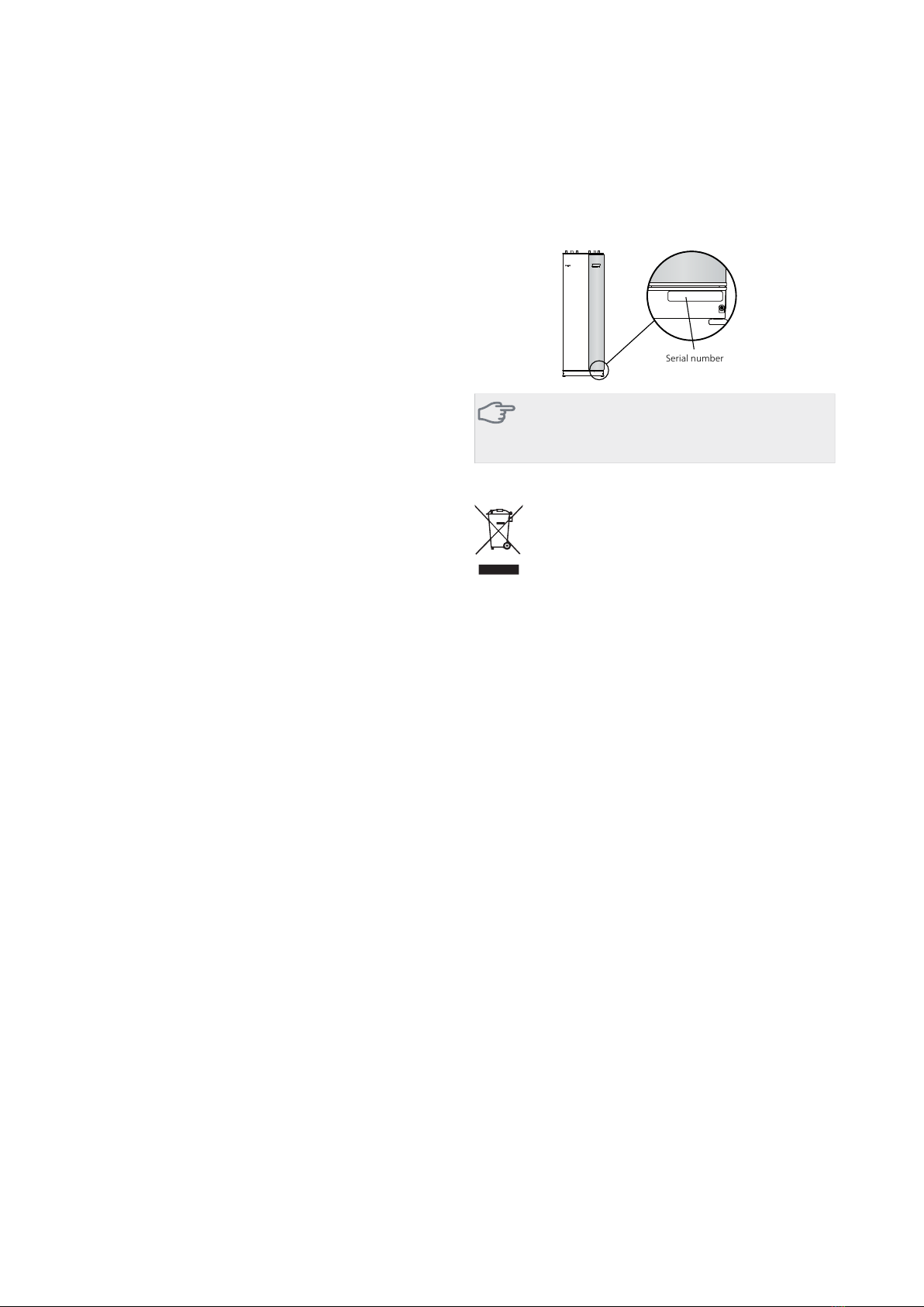
Serial number
The serial number can be found at the bottom right of
the front cover and in the info menu (menu 3.1) and on
the type plate (PF1).
Caution
You need the product's ((14 digit) serial number
for servicing and support.
Recovery
Leave the disposal of the packaging to the in-
staller who installed the product or to special
waste stations.
Do not dispose of used products with normal
household waste. It must be disposed of at a
special waste station or dealer who provides this type of
service.
Improper disposal of the product by the user results in
administrative penalties in accordance with current legis-
lation.
Environmental information
The equipment contains R407C or R410A, fluorinated
greenhouse gases with GWP values (Global Warming
Potential) of 1774 and 2088 respectively. Do not release
R407C or R410A into the atmosphere.
5Chapter 1 | Important informationF1345