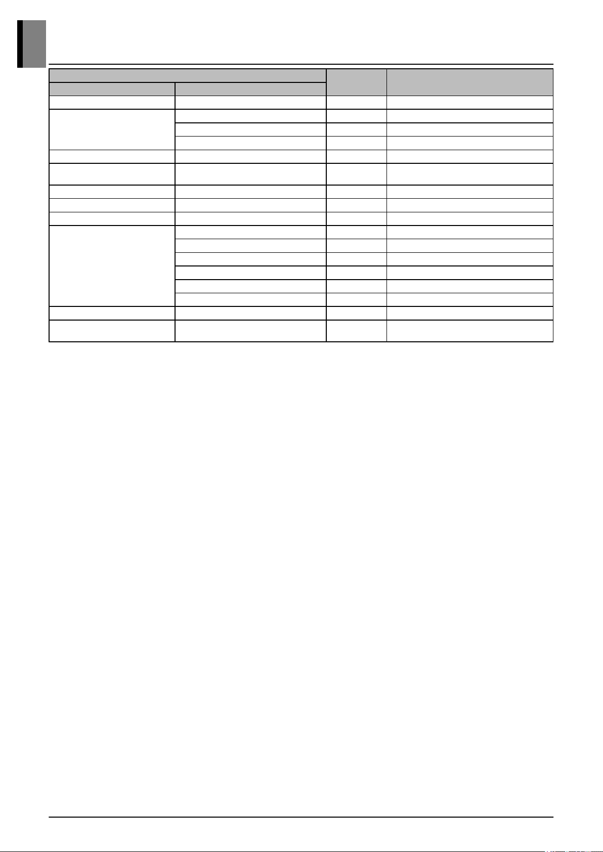
Category
Unit Specification
Major Minor
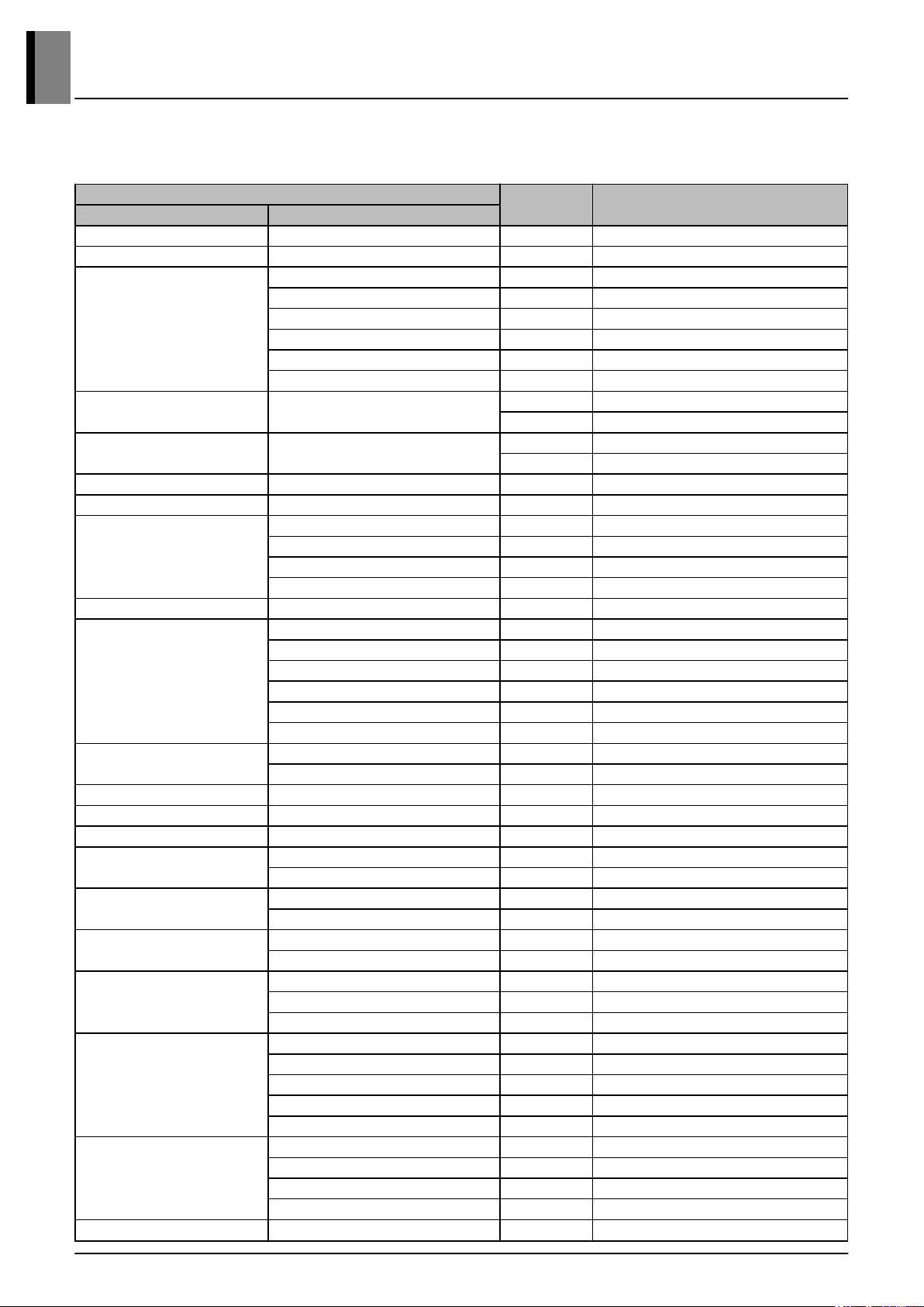
Piping Connection Type
Gas - Brazing
Low Pressure Gas (Heat Recovery) - Brazing
High Pressure Gas (Heat Recovery) - Brazing
Water Connecting Pipes
Inlet mm PT 40 (Internal Thread)
Outlet mm PT 40 (Internal Thread)
Drain Outlet mm PT 20 (External Thread)
Sound Pressure Level (Outdoor Unit) Cooling / Heating dB(A) 45.0 / 48.0
Measurement Standard (Pressure Leve
l) - - ISO 3741
Sound Power Level (Outdoor Unit) Cooling / Heating dB(A) 57.0 / 60.0
Measurement Standard (Power Level) - - -
Connecting Cable Communication Cable(VCTF-SB) mm² × cores 1.0 ~ 1.5 × 2C
Electrical Characteristic
Minimum Circuit Amperes (MCA) A 19.0
Maximum Fuse Amperes (MFA) A 20.0
Total Over Current Amperes (TOCA) A 20.0
Comp_Maximum Starting Current (MSC) A -
Comp_Rated Load Amperes (Cooling) A 9.2
Comp_Rated Load Amperes (Heating) A 9.9
Connectable indoor units number Max. (Conditional) Units 13(20)
Allowable Total Indoor Unit Connected
Capacity Ratio Min. / Max. (Conditional) % 50~130(200)
Note
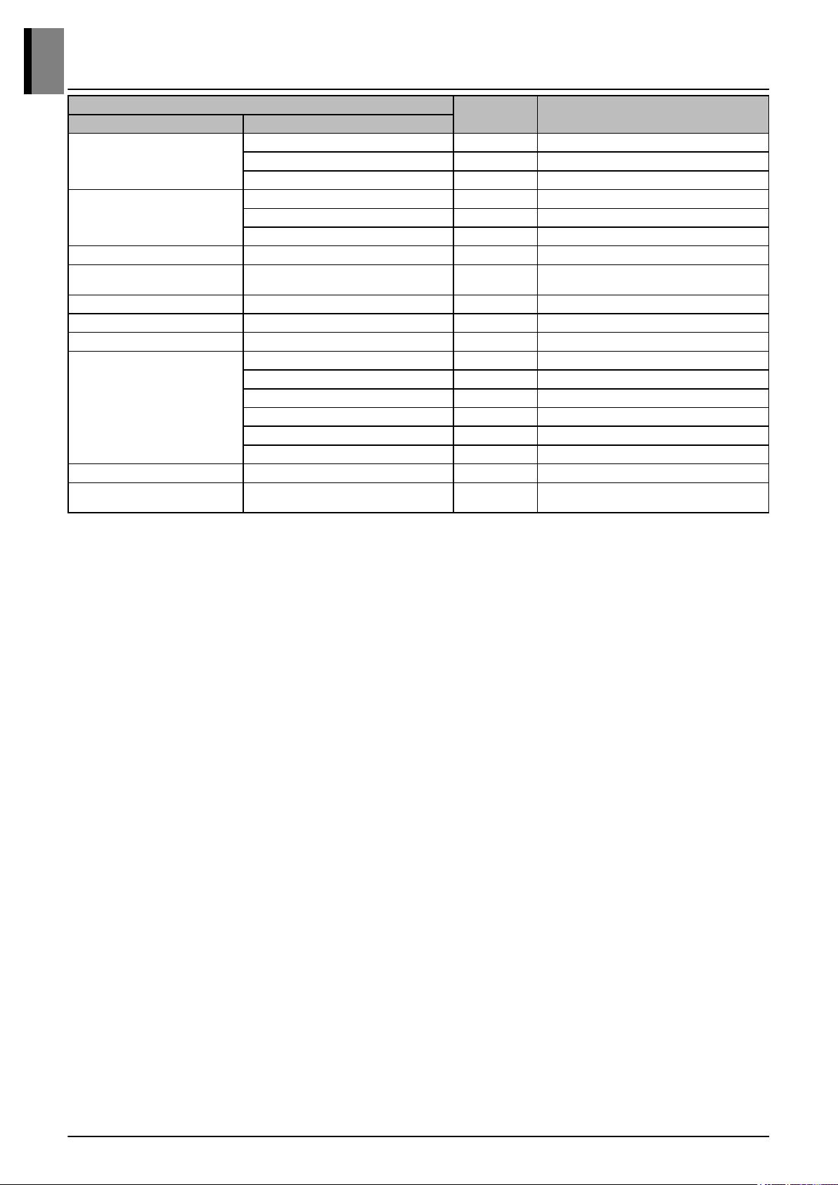
■ Due to our policy of innovation some specifications may be changed without notification.
■ The minimum flow rate of the product is based on 50% of the rated flow rate or the minimum flow rate value indicated in the specifications, whichever is
greater. However, when the 'Variable Water Flow Valve Control KIT' is applied, the minimum flow rate is allowed to 40% of the rated flow rate.
■ If the flow rate is less than minimum flow rate and the indoor unit combination ratio exceeds 130%, ask to LG Electronics even if the 'Variable Water Flow
Valve Control KIT' is applied.
■ Sound pressure level is measured on the rated condition in the anechoic rooms.
Sound power level is conversion value based on value measured in the anechoic rooms.
Therefore, these values can be increased owing to ambient conditions during operation.
■ Sound values of combination model are calculated values based on sound results of independent models.
Sound values of system [dB(A)] = 10*log [10^(A1/10)+ ... +10^(An/10)] , A1~An means sound values of independent models.
■ Of maximum connectable indoor units, the (conditional) number in parentheses means number in accordance with outdoor units combination (160~200%).
The recommended ratio is 130%.
■ Power factor could vary less than ±1% according to the operating conditions.
■ Voltage supplied to the unit terminals should be within the minimum and maximum range. Maximum allowable voltage unbalance between phase is 2%.
■ MSC and RLA values are compressor only test condition.
■ Select the wire size based on the larger value among MCA or TOCA. Wiring cable size must comply with the applicable local and national codes.
■ MFA is recommended fuse amperes.
■ TOCA is minimum required amperes for selecting the circuit breaker and ground fault circuit interrupter. Please select the circuit breaker size equal or greater
than TOCA.
■ All installation site must require attachment of an earth leakage breaker.[Circuit breaker type is ELCB (Earth Leakage Circuit Breaker)].
■ Select the electrical equipment of combination unit according to the electrical characteristics of individual unit.
■ Performances are based on the following conditions :
- Cooling : Indoor Ambient Temp. 27°CDB / 19°CWB, Water inlet temp. 30°C
- Heating : Indoor Ambient Temp. 20°CDB / 15°CWB, Water Inlet temp. 20°C
- Interconnected Pipe Length is 7.5m and difference of Elevation (Outdoor ~ Indoor Unit) is 0m.
Multi V Water 5
1. Specifications
Product Data
1-2