LG 32LH7*** series User manual

OWNER’S MANUAL
LCD TV MODELS
1199LLHH22******
2222LLHH22******
2266LLHH22******
3322LLHH22******
3377LLHH22******
4422LLHH22******
3322LLFF22******
4422LLFF22******
3322LLHH33******
3377LLHH33******
4422LLHH33******
4477LLHH33******
1199LLUU55******
2222LLUU55******
2266LLUU55******
LCD TV
Please read this manual carefully bef re perating
y ur TV.
Retain it f r future reference.
Rec rd the m del number and serial number f the
TV.
Refer t the label n the back c ver and qu te this
inf rmati n.
T y ur dealer when requiring any service.
ENGLISH
3377LLHH55******
4422LLHH55******
4477LLHH55******
5555LLHH55******
3322LLHH66******
4422LLHH66******
3322LLHH77******
3377LLHH77******
4422LLHH77******
4477LLHH77******
3322SSLL88******
4422SSLL88******
4477SSLL88******
5555SSLL88******
LED LCD TV MODELS
4422LLHH99******
4477LLHH99******
4422SSLL99******
4477SSLL99******
LED LCD TV

Wall Mounting Bracket(Separate purchase)
RW120
(19/22LH2***
19/22LU5***)
RW230
(26/32LH2*** 32LF2***
26LU5*** 32LH3***
32LH6*** 32LH7***
32SL8***)
AW-47LG30M
(32/37/42LH2*** 32/42LF2***
32/37/42/47LH3***
37/42/47LH5*** 32/42LH6***
32/37/42/47LH7*** 42/47LH9***
32/42/47SL8*** 42/47SL9***)
12mm 12mm
Use screws 12mm(+0.5/-0.5) long on the SET assembly side.(Separate purchase)
(
Only 42/47LH7*** 42/47SL8*** 42/47SL9***
)
AW-55LH40M
(55LH5*** 55SL8***)
Set assembly side
(without guide spacer)
Set assembly side
(with guide spacer)
Guide spacer
HDMI, the HDMI l g and High-Definiti n Multimedia
Interface are trademarks r registered trademarks f
HDMI Licensing LLC.
Only 32/42/47/55SL8***
Cable management
clip
(Refer to p.25)
Protection Cover
(Refer to p.22)
x 8
Bolts for stand
assembly
(Refer to p.20)
(Except 55SL8***)
Cable Holder
(Refer to p.25)
Only 42/47SL9***
Bolts for stand assembly
(Refer to p.20)
Cable Holder
(Refer to p.25)
20mm
x 3 x 4
16mm
Remote Controls
POWER
AV
MODE
ENERGY SAVING
P
A
G
E
P
FAV
MARK/
MUTE
ON/OFF
123
45
0
6
789
LIST
Q.VIEW
INPUT
MENU RATIO
Q.MENU
RETURN
OK
TV
OK
TV/INPUT
Batteries
x 2
1-screw for stand fixing
(Refer to p.23)
(Only 26/32/37/42LH2*** 32/42LF2***
26LU5*** 32/37/42LH3*** 37/42LH5***
32/42LH6*** 32/37LH7*** 42LH9***)
Cable management
clip
(Refer to p.25)

1
ACCESSORIES
ACCESSORIES
Ensure that the following accessories are included with your TV
If an accessory is missing, please contact the dealer where you purchased the TV
■
Here sh wn may be s mewhat different fr m y ur TV.
Owner’s Manual
Batteries (Except 42/47SL9***)
Remote Controls (Except 42/47SL9***)
Power Cord
Polishing Cloth
Polishing cloth for use on the screen.
This item is not included for all models.
* Lightly wipe any stains or fingerprints on
the surface of the TV with the polishing
cloth.
Do not use excessive force. This may cause
scratching or discolouration.
RARATIO
SLEEPSLEEP
ENERGY SAVING
Cable management clip
(Refer to p.25)
Protection cover
(Refer to p.22)
bolts for stand assembly (Refer to p. 19)
OOnnllyy 1199//2222LLHH22******
Protection cover
(Refer to p.21)
Only 32/37/42/47LH7***
AVMODEVMODE
ENERGYENERGYSASAVINGVING
RETURN
MENU
Q.MENU
MARK
MUTEMUTE
POWERPOWER
LISTLIST
Q.VIEWQ.VIEW
RARATIOTIO
FAV
AVMODE
ENERGYSAVING
MUTE
LIST
Q.VIEW
or
Bolts for stand assembly
(Refer to p.18)
Cable Holder
(Refer to p.24)
OOnnllyy 1199//2222//2266LLUU55******
Bolts for stand assembly
(Refer to p.19)
x 4
OOnnllyy 2266//3322//3377//4422LLHH22******,, 3322//3377//4422//4477LLHH33******,,
3377//4422//4477//5555LLHH55******,, 3322//4422LLHH66******,, 4422//4477LLHH99******
Protection cover
(Refer to p.22)
Cable management clip
(Refer to p.24)
Stand rear cover
(Refer to p.23)
(37LH7*** only)
x 8
(42LH7*** only)
x 3 x 4
M4x20 M4x16
M4x20
(32LH7*** only)
x 7
M4x20
(Only 19/22LU5***)(Only 26LU5***,)
x 2 x 3
Protective Bracket and Bolt for Power Cord
(Refer to P27)
(Only 37/42/47LH7***)
(47LH7*** only)
x 8
USB extension cable
Bolts for stand assembly
(Refer to p.18)
x 4
x 4
Protection Cover
(Refer to
p
22)
OOnnllyy 3322//4422LLFF22******
Make sure t use the pr vided USB extensi n cable,
Which is specially designed f r a slim fit.
or
M4x16
(Except 55LH5***)
or
POWERPOWER
TVTV
ON/OFFON/OFF
MARKMARK
FAV
AVMODEV MODE
or
POWERPOWER
TVTV
MARKMARK
FAV
AVMODEV MODE
or
AVMODE
ENERGYSAVING
MUTE
POWER
LIST
Q.VIEW
RATIO
AVMODEVMODE
ENERGYENERGYSASAVINGVING
RETURN
MENU
Q.MENU
MARK
MUTEMUTE
LISTLIST
Q.VIEWQ.VIEW
FAV
or

CONTENTS
2
CONTENTS
ACCESSORIES
. . . . . . . . . . . . . . . . . . . . . . . . . . . . . . . . . . . . . . . . . . . .
1
PREPARATION
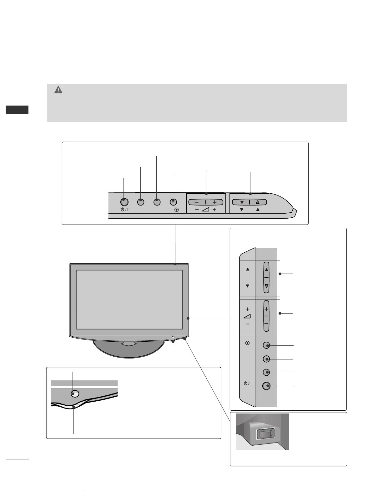
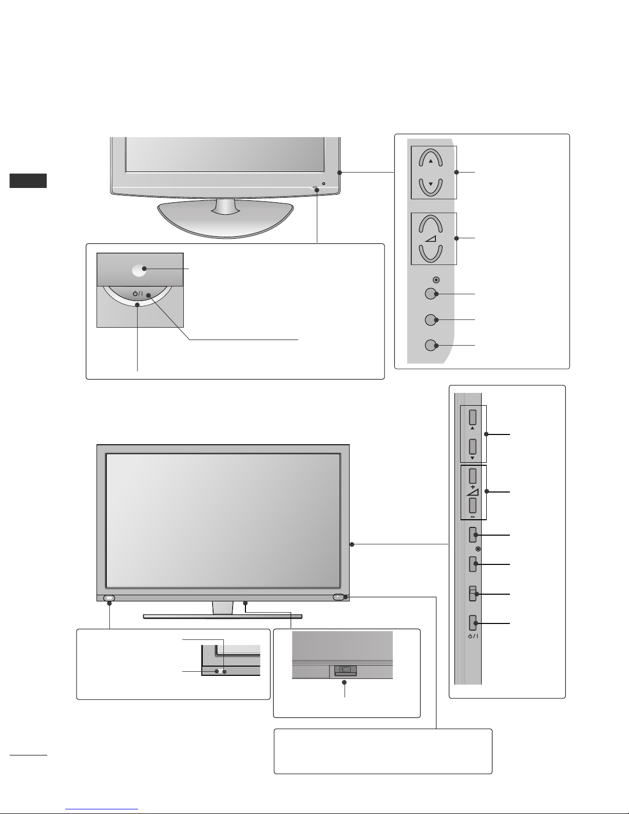
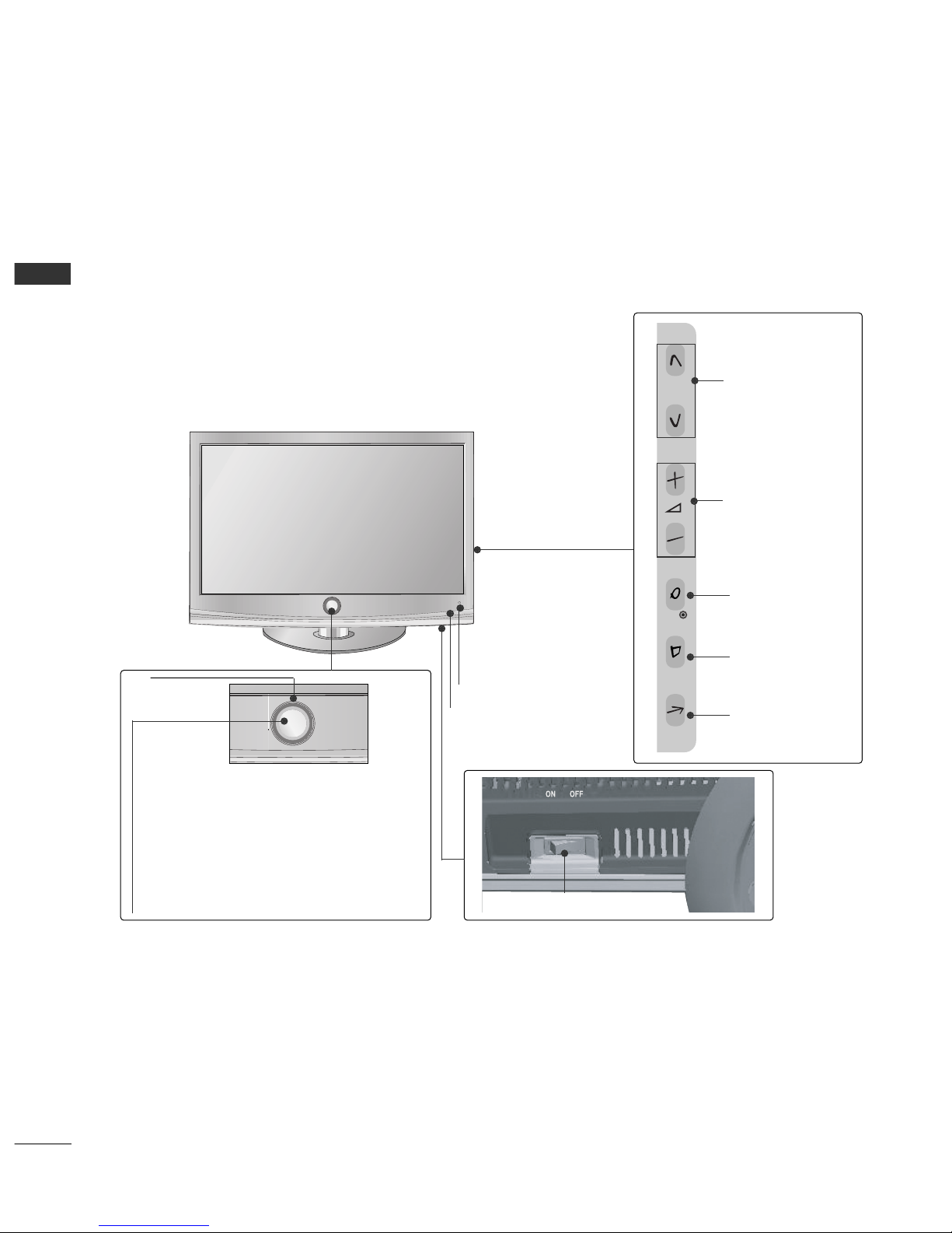
Fr nt Panel C ntr ls..................................................... 4
Back Panel Inf rmati n .............................................. 12
Stand Installati n......................................................... 18
N t Using the desk-type stand ................................21
Attaching the TV t a desk ........................................23
Swivel Stand ................................................................. 23
T Use The Stand Rear C ver ..................................23
P siti ning y ur display ........................................... 23
Back C ver f r Wire Arrangement.......................... 24
Detaching Stand.......................................................... 26
Kensingt n Security System......................................26
Careful Installati n Advice .........................................27
H w t Secure the P wer Cable ............................. 27
Deskt p Pedestal Installati n................................... 27
Wall M unt: H riz ntal Installati n........................ 28
Antenna C nnecti n.................................................. 29
EXTERNAL EQUIPMENT SETUP
HD Receiver Setup...................................................... 30
DVD Setup......................................................................33
VCR Setup..................................................................... 35
Other A/V S urce Setup............................................37
External Stere Setup ................................................ 38
AV Output Setup ........................................................ 39
Usb in Setup..................................................................40
PC Setup........................................................................ 41
- Screen Setup f r PC M de.............................. 44
WATCHING TV / PROGRAMME CONTROL
Rem te C ntr l Key Functi ns.................................48
Turning n the TV....................................................... 57
Pr gramme Selecti n ................................................ 57
V lume Adjustment ................................................... 57
Quick Menu ................................................................. 58
On-Screen Menus Selecti n and Adjustment..... 59
Aut Pr gramme Tuning............................................ 60
Manual Pr gramme Tuning ....................................... 61
Pr gramme Edit ........................................................... 63
Selecting the Pr gramme List .................................. 65
Fav urite Pr gramme Setup...................................... 66
Input List........................................................................ 67
Input Label .....................................................................68
..................................................................69
Key L ck......................................................................... 71
Initializing(Reset t riginal fact ry settings) ..... 72
AV M de........................................................................ 73
TO USE THE BLUETOOTH
Precauti ns when using the Bluet th ................. 74
Setting the Bluet th................................................. 75
Set TV PIN......................................................................76
Bluet th headset
- C nnecting a new Bluet th headset .............77
- C nnecting t Bluet th headset already
registered................................................................... 77
-
Disc nnecting the Bluet th headset during use
....78
- When requesting t c nnect t TV fr m the
Bluet th headset....................................................78
Managing Registered Bluet th device ................ 79
My Bluet th Inf rmati n. ........................................80
Receiving ph t s fr m external Bluet th device .........
81
Listening t the musics fr m external Bluet th device
81
TO USE A USB DEVICE
When c nnecting the USB device.......................... 82
Ph t List ...................................................................... 83
Music List........................................................................87
M vie List .......................................................................90
Divx Registrati n C de...............................................93
Deactivati n...................................................................94

CONTENTS
3
PICTURE CONTROL
Picture Size (Aspect Rati ) C ntr l....................... 95
Energy Saving.................................................... 97
Preset Picture Settings
- Picture M de-Preset............................................ 98
Manual Picture Adjustment
- Picture M de-User pti n................................. 99
Picture Impr vement Techn l gy......................... 100
Expert Picture C ntr l............................................. 101
Picture Reset .............................................................. 104
LED L cal Dimming................................................... 105
P wer Indicat r ...........................................................106
Dem M de................................................................ 107
M de Setting.............................................................. 108
SOUND & LANGUAGE CONTROL
Aut V lume Leveler..................................................109
Preset S und Settings - S und M de ................. 110
S und Setting Adjustment - User M de............. 111
SRS TruSurr und XT ................................................. 111
Ultra S und ................................................................. 112
Clear V ice ll................................................................ 113
Balance.......................................................................... 114
TV Speakers On/ Off Setup ................................... 115
Selecting Audi Out.................................................. 116
Audi Reset...................................................................117
I/II
- Stere /Dual Recepti n...................................... 118
- NICAM Recepti n ............................................................ 119
- Speaker S und Output Selecti n .................. 119
On-Screen Menu Language Selecti n....................... 120
TIME SETTING
Cl ck Setup................................................................. 121
Aut On/ Off Timer Setting ....................................122
Sleep Timer Setting .................................................. 122
TELETEXT
Switch n/ ff.............................................................. 123
SIMPLE Text..................................................................123
TOP Text...................................................................... 123
FASTEXT .......................................................................124
Special Teletext Functi ns....................................... 124
APPENDIX
Tr ublesh ting......................................................... 125
Maintenance ...............................................................127
Pr duct Specificati ns............................................. 128
IR C des ...................................................................... 133
External C ntr l Device Setup .............................. 135

PREPARATION
4
PREPARATION
FRONT PANEL CONTROLS
■
Here sh wn may be s mewhat different fr m y ur TV.
Only 32/37/42LH2***
32/37/42/47LH3***
INPUT MENU
P
OK
PROGRAMME
VOLUME
OK
Only 19/22/26LH2***
MENU
POWER
INPUT
INPUT
MENU
OK
P
PROGRAMME
VOLUME
OK
MENU
INPUT
POWER
Remote Control Sensor
Power/Standby Indicator
• Illuminates red in standby m de.
• Illuminates blue when the TV is switched n.
ON OFF
Only 19/22/26/32/37/42LH2*** 32/37/42/47LH3***
Main Power Switch
GGWhen the TV cann t be turned n with the rem te c ntr l, press the main p wer butt n n the TV.
(When the p wer is turned ff with the main p wer butt n n the TV, it will n t be turned n with the
rem te c ntr l.)
CAUTION
Except 19/22LH2***

5
PREPARATION
■
Here sh wn may be s mewhat different fr m y ur TV.
Only 19/22/26LU5***
P
INPUT
MENU
OK
P
P
PROGRAMME
VOLUME
OK
MENU
INPUT
POWER
INPUT MENU
OK
P
Only 19/22LU5***
Only 26LU5***
VOLUME
POWER INPUT MENU OK PROGRAMME
Main
Power
Switch
ON
OFF
P
Remote Control Sensor
Power/Standby Indicator
Illuminates red in standby m de.
Illuminates white when the TV is switched n.

6
PREPARATION
PREPARATION
P
MENU
INPUT
OK
+
-
PROGRAMME
VOLUME
OK
MENU
INPUT
POWER Button
Power/Standby Indicator
• illuminates red in standby m de.
• illuminates blue when the TV is switched n.
Remote Control Sensor
Only 32/42LF2***
■
Here sh wn may be s mewhat different fr m y ur TV.
■
Here sh wn may be s mewhat different fr m y ur TV.
Main Power Switch
OFF ON
INPUT
MENU
OK
P
PROGRAMME
VOLUME
MENU
OK
INPUT
POWER
Intelligent Sensor
Adjusts picture acc rding t
the surr unding c nditi ns.
Remote Control Sensor
Power/Standby Indicator
• Illuminates red in standby m de.
• Illuminates white when the TV is switched n.
Only 42/47SL9***

7
PREPARATION
Only 37/42/47/55LH5***
■
Here sh wn may be s mewhat different fr m y ur TV.
INPUT
MENU
OK
P
PROGRAMME
VOLUME
OK
MENU
INPUT
POWER
Remote Control Sensor
Intelligent Sensor
Adjusts picture acc rding t
the surr unding c nditi ns.
Power/Standby Indicator
• Illuminates red in standby m de.
• Illuminates blue when the TV is switched n.
OFF ON
Main Power Switch

8
PREPARATION
PREPARATION
Only 32/37/42/47LH7***
■
Here sh wn may be s mewhat different fr m y ur TV.
P
P
OK
MENU
INPUT
P
PROGRAMME
VOLUME
OK
MENU
INPUT
Intelligent Sensor
Adjusts picture acc rding t
the surr unding c nditi ns
POWER(Touch Sensor)
Power/Standby Indicator
• Illuminates red in standby mode
• Illuminates Whitish when the TV is switched on
Note: You can adjust PPoowweerr IInnddiiccaattoorrin the
OPTION menu
Moving LED
Main Power Switch
Remote Control Sensor

9
PREPARATION
Only 42/47LH9***
INPUT
MENU
OK
P
PROGRAMME
VOLUME
OK
MENU
INPUT
POWER
Remote Control Sensor
Intelligent Sensor
Adjusts picture acc rding t
the surr unding c nditi ns.
Power/Standby Indicator
• Illuminates red in standby m de.
•
Illuminates white when the TV is switched n.
SPEAKER
Main Power Switch
■
Here sh wn may be s mewhat different fr m y ur TV.

10
PREPARATION
PREPARATION
■
Here sh wn may be s mewhat different fr m y ur TV.
Only 32/42LH6***
PROGRAMMEVOLUMEMENU OKINPUTPOWER
Remote Control Sensor
Intelligent Sensor
Adjusts picture acc rding t the surr unding c nditi ns.
Power/Standby Indicator
•
Illuminates red in standby m de.
• Illuminates blue when the TV is switched n.
Main Power Switch
Power Indicator(Only 42LH6***)
• Illuminates blue when the TV is switched n.

11
PREPARATION
Only 32/42/47/55SL8***
■
Here sh wn may be s mewhat different fr m y ur TV.
Main Power Switch
OFF ON
INPUT
MENU
OK
P
PROGRAMME VOLUME MENU
OK INPUT POWER
(Only 42/47/55SL8***)
Main Power Switch
OFFON
(Only 32SL8***)
Intelligent Sensor
Adjusts picture acc rding
t the surr unding
c nditi ns.
Remote Control
Sensor
Power/Standby Indicator
• Illuminates red in standby m de.
•
Illuminates blue when the TV is switched n.

12
PREPARATION
PREPARATION
■
Here sh wn may be s mewhat different fr m y ur TV.
L( MONO)
R
AUDIO
VIDEO
VARIABLE AUDIO OUT
ANTENNA IN
L( MONO)
R
AUDIO
VIDEO
VARIABLE AUDIO OUT
ANTENNA
IN
Only 19/22/26/32/37/42LH2*** 32/42LF2*** 32/37/42/47LH3***
(Refer to p.13)
COMPONENT IN
AUDIO
VIDEO
L(L(MONO)MONO)
R
AUDIOAUDIO
AV IN
VIDEOVIDEO
IN
OUT
VARIABLE AUDIO OUTVARIABLE AUDIO OUT
ANTENNA IN
HDMI/DVI IN RGB IN
(PC)
RS-232C IN
(CONTROL)
AUDIO IN
(RGB/DVI)
USB IN
SERVICE ONLY
L(MONO)
R
AUDIO
VIDEO
VARIABLE AUDIO OUT
ANTENNA
IN
3
2
79
L(MONO)
R
AUDIO
VIDEO
VARIABLE AUDIO OUT
ANTENNA IN
AUDIO
VIDEO
L(L(MONO)MONO)
R
AUDIOAUDIO
AV
VIDEOVIDEO
IN
OUT
VARIABLE AUDIO OUTVARIABLE AUDIO OUT
ANTENNA
IN
HDMI
/DVI IN
RGB IN
(PC)
RS-232C IN
(CONTROL)
AUDIO IN
(RGB/DVI)
USB IN
SERVICE ONLY
HDMI
1
2
ANTENNA
IN
L/MONO
R
AUDIO
VIDEO
VARIABLE AUDIO OUT
COMPONENT IN
456
10
8
Only 26/32/37/42LH20**
Only 19/22LH2***
Only 32/37/42/47LH3*** 32/37/42LH23**
6
3
245
7910
8
L(MONO)
R
AUDIO
VIDEO
VARIABLE AUDIO OUT
ANTENNA IN
L(MONO)
R
AUDIO
VIDEO
VARIABLE AUDIO OUT
ANTENNA
IN
COMPONENT IN
AUDIO
VIDEO
ANTENNA
IN
HDMI
/DVI IN
RGB IN
(PC)
RS-232C IN
(CONTROL)
AUDIO IN
(RGB/DVI)
HDMI
1
2
AV OUT
L/L/MONOMONO
R
AUDIOAUDIO
VIDEOVIDEO
VARIABLE AUDIO OUTVARIABLE AUDIO OUT
AV IN1
Only 32/37/42/47LH3*** 32/37/42LH23**
6
3
24
7910
8
L( MONO)
R
AUDIO
VIDEO
VARIABLE AUDIO OUT
ANTENNA IN
AV IN2
IN 3
L( MONO)
R
AUDIO
VIDEO
VARIABLE AUDIO OUT
ANTENNA
IN
ANTENNA
IN
L/MONO
R
AUDIO
VIDEO
VARIABLE AUDIO OUT
2
8
11
1
AUDIO
VIDEO
L(
L(
MONO)
MONO)
R
AUDIO
AUDIO
AV
VIDEO
VIDEO
IN1
OUT
VARIABLE AUDIO OUT
VARIABLE AUDIO OUT
HDMI/DVI IN RGB IN
(PC)
RS-232C IN
(CONTROL)
AUDIO IN
(RGB/DVI)
USB IN
SERVICE ONLY
ANTENNA
IN
1
COMPONENT IN
3
2
79
456
10
8
Only 32/42LF2***
Only 32/42LF2***
L( MONO)
R
AUDIO
VIDEO
VARIABLE AUDIO OUT
ANTENNA
IN
AV IN2
IN 2
2
8
BACK PANEL INFORMATION

13
PREPARATION
L( MONO)
R
AUDIO
VIDEO
VARIABLE AUDIO OUT
ANTENNA IN
L( MONO)
R
AUDIO
VIDEO
VARIABLE AUDIO OUT
ANTENNA
IN
L( MONO)
R
AUDIO
VIDEO
VARIABLE AUDIO OUT
ANTENNA IN
L( MONO)
R
AUDIO
VIDEO
VARIABLE AUDIO OUT
ANTENNA
IN
AV IN2
IN 3
2
8
Only 26LU5***
ON
OFF
1
Power Cord Socket
This TV perates n an AC p wer. The v ltage is
indicated n the Specificati ns page. Never
attempt t perate the TV n DC p wer.
HDMI Input
C nnect a HDMI signal t HDMI IN.
Or DVI(VIDEO)signal t HDMI/DVI p rt with DVI
t HDMI cable.
RS-232C IN PORT
C nnect t the RS-232C p rt n a PC.
This p rt is used f r Service r H tel m de.
RGB IN Input
C nnect the utput fr m a PC.
SERVICE ONLY PORT
RGB/DVI Audio Input
C nnect the audi fr m a PC.
Component Input
C nnect a c mp nent vide /audi device t
these jacks.
Audio/Video Input
C nnect audi /vide utput fr m an external
device t these jacks.
AV Output
C nnect sec nd TV r m nit r t the AV OUT
s cket n the TV.
Variable Audio Output
C nnect an external amplifier r add a subw fer
t y ur surr und s und system.
Antenna Input
C nnect RF antenna t this jack.
USB IN Input
C nnect USB st rage device t this jack.
1
2
3
4
5
6
8
9
10
11
7
L/MONO
R
AUDIO
VIDEO
VARIABLE AUDIO OUT
ANTENNA
IN
AV IN2
IN 3
L/MONO
R
AUDIO
VIDEO
VARIABLE AUDIO OUT
ANTENNA
IN
11
2
8
1
Only 19/22/26LU5*** 37/42/47/55LH5*** 42/47LH9***
■
Here sh wn may be s mewhat different fr m y ur TV.
AV OUT
L/L/MONOMONO
R
AUDIOAUDIO
VIDEOVIDEO
VARIABLE AUDIO OUTVARIABLE AUDIO OUT
ANTENNA
IN
RGB IN
(PC)
RS-232C IN
(CONTROL)
AUDIO IN
(RGB/DVI)
1
2
COMPONENT IN
AUDIO
VIDEO
1(DVI)
2
AV IN1
/DVI IN
L/MONO
R
AUDIO
VIDEO
VARIABLE AUDIO OUT
ANTENNA
IN
3
2
79
46
10
8
Only 19/22/26LU5***
COMPONENT IN
AUDIO
VIDEO
HDMI/DVI IN
RGB IN
(PC)
RS-232C IN
(CONTROL)
AUDIO IN
(RGB/DVI)
USB IN
SERVICE ONLY
L(L(MONO)MONO)
R
AUDIOAUDIO
VIDEOVIDEO
1(DVI)
2
ANTENNA
IN
AV OUT
VARIABLE AUDIO OUTVARIABLE AUDIO OUT
AV IN
L(MONO)
R
AUDIO
VIDEO
ANTENNA
IN
VARIABLE AUDIO OUT
3
2
79
456
10
8
L(MONO)
R
AUDIO
VIDEO
ANTENNA
IN
VARIABLE AUDIO OUT
L(MONO)
R
AUDIO
VIDEO
ANTENNA
IN
VARIABLE AUDIO OUT
AV IN1
Only 26LU5***

14
PREPARATION
PREPARATION
L/ MONO
R
AUDIO
VIDEO
VARIABLE AUDIO OUT
ANTENNA
IN
1
Only 32/42LH6***
Power Cord Socket
This TV perates n an AC p wer. The v ltage is
indicated n the Specificati ns page. Never
attempt t perate the TV n DC p wer.
HDMI Input
C nnect a HDMI signal t HDMI IN.
Or DVI(VIDEO)signal t HDMI/DVI p rt with DVI
t HDMI cable.
RGB IN Input
C nnect the utput fr m a PC.
RGB/DVI Audio Input
C nnect the audi fr m a PC.
Component Input
C nnect a c mp nent vide /audi device t
these jacks.
Audio/Video Input
C nnect audi /vide utput fr m an external
device t these jacks.
AV Output
C nnect sec nd TV r m nit r t the AV OUT
s cket n the TV.
Variable Audio Output
C nnect an external amplifier r add a subw fer
t y ur surr und s und system.
Antenna Input
C nnect RF antenna t this jack.
USB IN Input
C nnect USB st rage device t this jack.
1
2
3
4
5
7
6
8
9
L/MONO
R
AUDIO
VIDEO
VARIABLE AUDIO OUT
ANTENNA
IN
AV IN2
IN 3
6
AV OUT
L/
L/
MONO
MONO
R
AUDIO
AUDIO
VIDEO
VIDEO
VARIABLE AUDIO OUT
VARIABLE AUDIO OUT
ANTENNA
IN
RGB IN
(PC)
AUDIO IN
(RGB/DVI)
1
2
COMPONENT IN
AUDIO
VIDEO
1(DVI)
2
AV IN1
/DVI IN
■
Here sh wn may be s mewhat different fr m y ur TV.
2
57
34
8
6
9
2

15
PREPARATION
1
2
AUDIO IN
(RGB/DVI)
RGB IN
(PC)
RGB IN
COMPONENT IN
AUDIO
VIDEO
L/L/MONOMONO
R
AUDIOAUDIO
VIDEOVIDEO
VARIABLE AUDIO OUTVARIABLE AUDIO OUT
AV IN1 AV OUT
AV IN2
ANTENNA IN
RS-232C IN
(CONTROL)
2
57
1
Only 32/37/42/47LH7***
Power Cord Socket
This TV perates n an AC p wer. The v ltage is
indicated n the Specificati ns page. Never
attempt t perate the TV n DC p wer.
RGB IN Input
C nnect the utput fr m a PC.
RGB/DVI Audio Input
C nnect the audi fr m a PC.
Audio/Video Input
C nnect audi /vide utput fr m an external
device t these jacks.
RS-232C IN PORT
C nnect t the RS-232C p rt n a PC.
This p rt is used f r Service r H tel m de.
Component Input
C nnect a c mp nent vide /audi device t
these jacks.
AV Output
C nnect sec nd TV r m nit r t the AV OUT
s cket n the TV.
Variable Audio Output
C nnect an external amplifier r add a subw fer
t y ur surr und s und system.
Antenna Input
C nnect RF antenna t this jack.
USB IN Input
C nnect USB st rage device t this jack.
HDMI Input
C nnect a HDMI signal t HDMI IN.
Or DVI(VIDEO)signal t HDMI/DVI p rt with DVI
t HDMI cable.
1
2
3
4
6
7
8
4
3
6
L/MONO
R
AUDIO
VIDEO
VARIABLE AUDIO OUT
ANTENNA IN
1(DVI)
2
/DVI IN
3
8
9
5
9
■
Here sh wn may be s mewhat different fr m y ur TV.

16
PREPARATION
PREPARATION
Only
32/42/47/55SL8***
Power Cord Socket
This TV perates n an AC p wer. The v ltage is
indicated n the Specificati ns page. Never
attempt t perate the TV n DC p wer.
HDMI IN Input
C nnect a HDMI signal t HDMI IN. Or DVI (VIDEO)
signal t HDMI/DVI p rt with DVI t HDMI cable.
RGB IN Input
C nnect the utput fr m a PC.
Audio/Video Input
C nnect audi /vide utput fr m an external
device t these jacks.
RGB/DVI Audio Input
C nnect the audi fr m a PC.
Component Input
C nnect a c mp nent vide /audi device t
these jacks.
AV Output
C nnect sec nd TV r m nit r t the AV OUT
s cket n the TV.
Variable Audio Output
C nnect an external amplifier r add a subw fer
t y ur surr und s und system.
Antenna Input
C nnect RF antenna t this jack.
USB IN Input
C nnect USB st rage device t this jack.
1
2
3
4
5
6
7
8
9
■
Here sh wn may be s mewhat different fr m y ur TV.
AV IN 2
L/MONO
R
AUDIOAUDIO
VIDEOVIDEO
L/ MONO
R
AUDIO
VIDEO
VARIABLE AUDIO OUT
4
AV IN 2
L/MONO
R
AUDIO
VIDEO
L/ MONO
R
AUDIO
VIDEO
VARIABLE AUDIO OUT
1
AV IN 2
L/MONO
R
AUDIO
VIDEO
IN 3
L/ MONO
R
AUDIO
VIDEO
VARIABLE AUDIO OUT
9
2
AV IN 2
L/MONO
R
AUDIO
VIDEO
2
IN /DVI IN
1
1
2
COMPONENT IN
AUDIO
VIDEO
AV OUT
L/
L/
MONO
MONO
R
AUDIO
AUDIO
VIDEO
VIDEO
VARIABLE AUDIO OUT
VARIABLE AUDIO OUT
AV IN 1
RGB IN
(PC)
AUDIO IN
(RGB/DVI)
ANTENNA
IN
3
25
68
4
7

17
PREPARATION
■
Here sh wn may be s mewhat different fr m y ur TV.
L/ MONO
R
AUDIO
VIDEO
VARIABLE AUDIO OUT
1
IN 3
L/ MONO
R
AUDIO
VIDEO
VARIABLE AUDIO OUT
10
2
Only
42/47SL9***
2
IN /DVI IN
1
1
2
COMPONENT IN
AUDIO
VIDEO
AV OUT
L/L/MONOMONO
R
AUDIOAUDIO
VIDEOVIDEO
VARIABLE AUDIO OUTVARIABLE AUDIO OUT
AV IN
RGB IN
(PC)
AUDIO IN
(RGB/DVI)
ANTENNA
IN
(CONTROL)
RS-232C IN
4
26
79
5
8
3
Power Cord Socket
This TV perates n an AC p wer. The v ltage is
indicated n the Specificati ns page. Never
attempt t perate the TV n DC p wer.
HDMI IN Input
C nnect a HDMI signal t HDMI IN. Or DVI (VIDEO)
signal t HDMI/DVI p rt with DVI t HDMI cable.
RGB IN Input
C nnect the utput fr m a PC.
RS-232C IN PORT
C nnect t the RS-232C p rt n a PC.
This p rt is used f r Service r H tel m de.
Audio/Video Input
C nnect audi /vide utput fr m an external
device t these jacks.
RGB/DVI Audio Input
C nnect the audi fr m a PC.
Component Input
C nnect a c mp nent vide /audi device t
these jacks.
AV Output
C nnect sec nd TV r m nit r t the AV OUT
s cket n the TV.
Variable Audio Output
C nnect an external amplifier r add a subw fer
t y ur surr und s und system.
Antenna Input
C nnect RF antenna t this jack.
USB IN Input
C nnect USB st rage device t this jack.
1
2
3
4
5
7
8
9
10
6
CAUTION
GUse a pr duct with the f ll wing thickness
f r ptimal c nnecti n t HDMI cable ( nly
HDMI IN 3) / USB device.
*A 10mm

18
PREPARATION
PREPARATION
STAND INSTALLATION
■
Here sh wn may be s mewhat different fr m y ur TV.
When assembling the desk type stand, check whether the b lt is fully tightened. (If n t tightened fully, the pr duct can
tilt f rward after the pr duct installati n.) If y u tighten the b lt with excessive f rce, the b lt can deviate fr m abrasi n
f the tightening part f the b lt.
Only 19/22/26LU5***
1
2
Carefully place the TV screen side d wn n a cush-
i ned surface t pr tect the screen fr m damage.
Fix the 2 r 3 b lts securely using the h les as
sh wn.
1Carefully place the TV screen side d wn n a cush-
i ned surface t pr tect the screen fr m damage.
2Assemble the TV as sh wn.
Only 19/22LH2***
Cover Base
(Only 26LU5***)
1
3
4
Carefully place the TV screen side d wn n a
cushi ned surface t pr tect the screen fr m
damage.
2Assemble the parts f the SSttaanndd BBddyywith
the SSttaanndd BBaasseef the TV.
Assemble the TV as sh wn.
Fix the 4 b lts securely using the h les in the
back f the TV.
Stand Body
Stand Base
Only 32/42LF2***
This manual suits for next models
142
Table of contents
Other LG LCD TV manuals