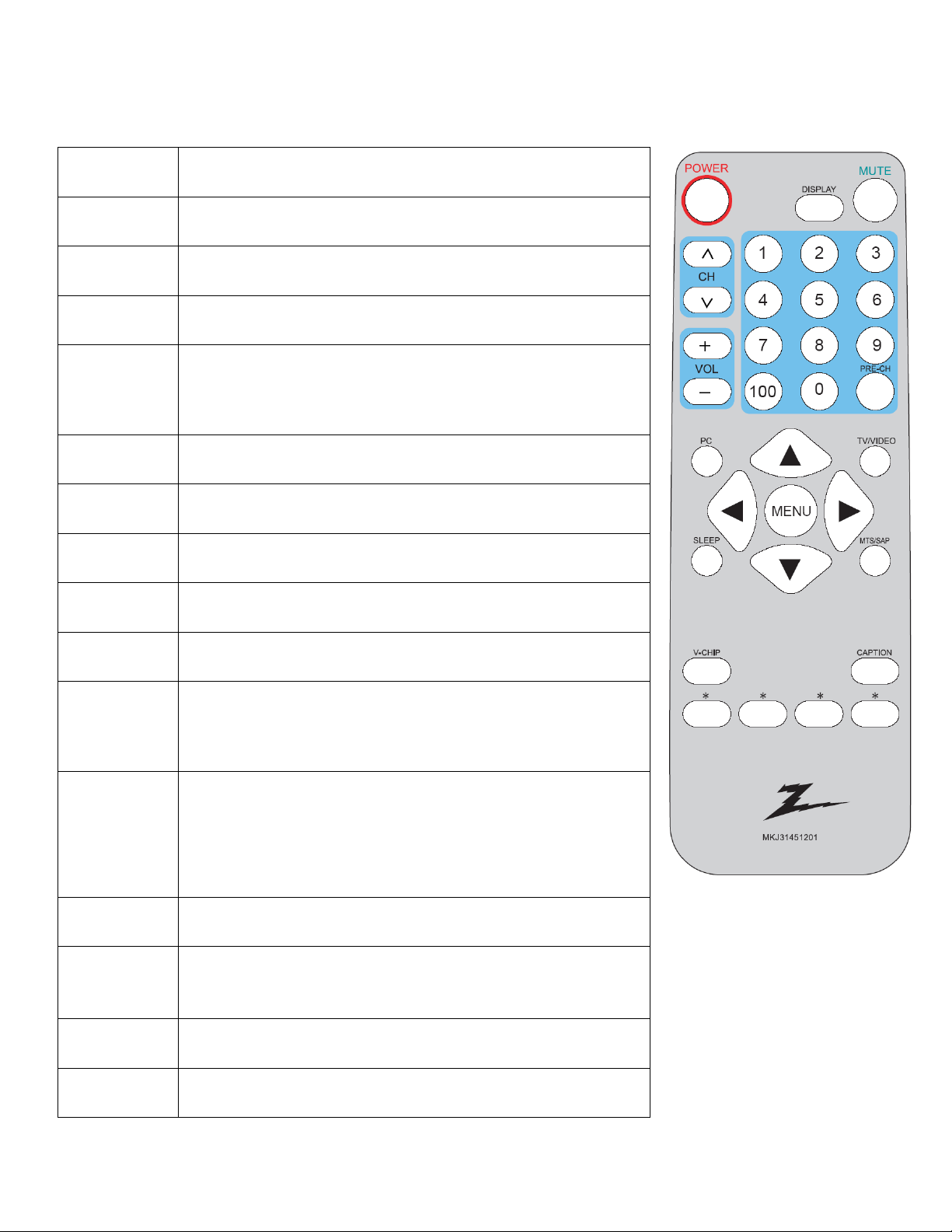
LG Z20LCD1 User manual

- 1 -
Website:http://biz.LGservice.com
e-mail: http://www.LGEservice.com/techsup.html
LCD TV SERVICE
MANUAL
FACTORY MODEL: 20LV1R.AUSBZA
MODEL: Z20LCD1
CAUTION
BEFORE SERVICING THE CHASSIS,
READ THE SAFETY PRECAUTIONS IN THIS MANUAL.

- 2 -
CONTENTS
CONTENTS ......................................................................................................................................2
PRODUCT SAFETY .......................................................................................................................3
SPECIFICATION ...............................................................................................................................6
SVC REMOCON……………... .....................................................................................................8
TROUBLE SHOOTING ..................................................................................................................9
BLOCK DIAGRAM.........................................................................................................................13
WIRING DIAGRAM .........................................................................................................................15
EXPLODED VIEW ...............……………………………................................................................... 16
REPLACEMENT PARTS LIST ............................…...............……………………………................ 18
SVC. SHEET .................................................................................................................................

- 3 -
SAFETY PRECAUTIONS

- 4 -
SERVICING PRECAUTIONS

- 5 -
.

- 6 -

- 7 -
SPECIFICATION
NOTE: Specifications and others are subject to change without notice for improvement.
1. Application range
1.1 This spec sheet is applied all of the 20" LCD TV
1.2 Not included spec and each product spec in this spec sheet apply correspondingly to the following each country
standard and requirement of Buyer
2. Specification
Each part is tested as below without special appointment.
2.1 Temperature: 20±5°C
2.2 Relative Humidity: 65±20%
2.3 Power Voltage: input voltage (110V±10%, 50/60±3 Hz)
* Standard Voltage of each product is marked by models
2.4 Specification and performance of each parts are followed each drawing and specification by part number in
accordance with BOM.
2.5 The receiver must be operated for about 30 minutes prior to the adjustment.
3.General Specification (TV)
No Item Specification
1. Input Signal RF (NTSC-M), Video, S-Video, Component Video, Graphic (VGA)
2.
Component Support 480i, 576i, 480P, 576P, 720P, 1080i
3. Input Voltage 110V±10%, 50/60±3 Hz
4. Market USA
5. Screen Size 20 inch Wide
6. Vertical refresh rate 56 Hz to 75 Hz
7. Horizontal frequency 31.5 kHz
8.
Resolutions
640 x 480
9.
Operating Environment Temp: 0 ~ 40 deg, Humidity: 10% ~ 80 %
10.
Storage Environment
Temp: -10 ~ 50 deg, Humidity: 5% ~ 85 %

- 8 -
4. External Input Format
4-1. AV/S-Video/Component Video Inputs
AV (Composite Video)
Video system NTSC
Amplitude 1.0Vpp (including sync)
Impedance 75 ohm terminated
S-Video
Video system NTSC
Y signal amplitude 1.0Vpp (including sync)
C signal amplitude 0.286Vpp
Impedance 75 ohm terminated
Component Video
HDTV 480i, 480p, 720p, 1080i
Y signal amplitude 1.0Vpp (including sync)
Pr,(R-Y) / Pb ,(B-Y) signal amplitude 0.7Vpp
Impedance 75 ohm terminated
4-2. TV RF Inputs
TUNER SIGNAL
Receiving System NSTC-M
Channel Coverage NSTC-M
Tuner ChangHong AF5-U2F11RW
AIR CATV
VHF Low band 55.25~127.25 55.25~127.25
VHF High band 133.25~361.25 133.25~361.25
UHF band 367.25~801.25 367.25~801.25
Picture carrier Sound carrier
IF Frequency 45.75 MHz 41.25MHz
Impedance 75 ohm terminated
LEVEL 70dBuV

- 9 -

- 10 -
SVC REMOCON
Key Function
POWER Press to turn on/off the TV. The TV is never completely powered
off unless it is physically unplugged.
DISPLAY Display current status
MUTE Temporarily interrupt the sound or restore
CH
Press ▲ or▼ to brows through the TV channels which are not
erased. To view a blocked channel, use the digit buttons to access
the channel and enter your access code.
VOL Press + or – to adjust the volume.
0~9/100 To select a TV channel directly
PRE-CH To return the last channel you were watching.
PC To change PC mode (only for Z15LCD1)
V-CHIP Press this button to setup parental control.
TV/VIDE
O
Select your input source: press repeatedly to select TV, AV1, AV2,
S-Video or Component Video mode, according to where you
connected your external source.
SLEEP
With this key you can set a time period after which the TV should
switch itself to standby. Press the key repeatedly to select the
number of minutes. The counter runs from 0,30,60,90,120
minutes. The timer begins to count down from the number of
minutes selected after the display has disappeared.
MTS/SAP Press this key to activate Multi-channel Television Sound, Stereo
or Mono sound.
Up/Down/
Left/Right
Up/Down to select the function in the Menu.
Left/Right to enter the function or adjust the value
MENU Press repeatedly to display OSD menu or exit the menu or
sub-menu.
CAPTION Press this button to bring up closed caption setup menu.

- 11 -
TROUBLE SHOOTING
1. No Power (No LED indicator)
No Power
Check power
cord and board
NG
Plug in power cord and interface
OK
Check F901, BD901
NG
Replace F901 or BD901
OK
Check the load
Check IC901
NG
Replace IC901 or Q901
OK
Check T901
NG
Replace T901
OK
Check D904, D905
Replace D904, D905
NG
OK
Replace Q903, ZD902, IC903 IC902
Check Q903, ZD902, IC903 IC902 and
NG
OK
Check Q906, IC905 and relative circuit

- 12 -
2. No Display (LED indicator green)
3. Can’t start (LED indicator yellow)
Check the source
OK
Reset source
NG
Check LVDS cable
NG
Replace LVDS cable
OK
Check 12V power supply
NG
Return to “1”
OK
OK
Check U406
NG
Replace U406
OK
OK
Check panel
NG
Replace panel
Check main board power
Check I2C communication
Repair I2C communication relative circuit
NG
No display
NG
Repair the keyboard
OK
Check 5V_SB
NG
Check every chip power supply
OK
NG
Check I2C communication
OK
Check keyboard
Replace I2C communication component
Check oscillistor
NG
Replace oscillistor
Can’t start

- 13 -
4. Abnormal Display
Check the source
OK
Reset source
NG
Check signal filter circuit
NG
Replace the filter or inductance
Repair each relative circuit
RF signal
Check TV system setup
OK
Check TU100
Replace TU100
AV, S-video signal
component PC signal
OK
Check LVDS cable
Check input signal
OK
OK
OK
NG
Replace LVDS cable
OK
Check panel
Replace panel
NG
Abnormal display

- 14 -
5. No Sound
Check the source
OK
Reset source
Check signal filter circuit
NG
Replace the filter or inductance
OK
NG
SIF signal
Check TV system setup
OK
Check TU100
Replace TU100
AV, component, S-video, PC signal
NG
Check Amplifier TDA7266D U601
Replace U601
Check Earphone jack
NG
Replace the Earphone jack
OK
Check speaker
NG
Replace speaker
Check relative circuit
NG
No sound

- 15 -
BLOCK DIAGRAM
1. Main Board
PHILIPS LOC1 TV Block Diagram
Speaker (2Wx 2)
Philips
LOC1
TDA15501E
Key PAD
VIDEO 1
S-VIDEO
IF Tuner
Philips
1336MK
TDA7266D
Audio AMP
Headphone
SDA/SCL
IR
PC D-sub
Flash
SST39V F020B
Video IF
Audio IF
Audio Output
HD input
RGB
Y/PR/PB
PI5V
330W
PI5V
330W
RGB Gain Input
PC Audio
AV Audio
HD Audio
Switch
4052
Video H/V Output
PC H/V Input
Select H/V Input
SDA/SCL
TTL output
TTL TO LVDS
THC63LVDM84R
LVDS output
PANEL
AU or CPT
Power Internal
AC 100~220 Input
Inverter For TV
DC 12V
DC 5V
Inverter
Switch
4052
DDC
EEPROM
SDA/SCL
EEPROMM24C32
32K
VSCL/VSDA
SawFilter /VF45A3M
SawFilter /AF45A3M

- 16 -
2. Power Board

- 17 -
WIRING DIAGRAM

- 18 -
EXPLODED VIEW

- 19 -
EXPLODED VIEW PARTS LIST
No. LG Part No. TPV Part No. Desc. Q'TY
010 EBU32316701 CBPFAA6KCHLTP MAIN BOARD 1
020 EBU32326801 PWTVA62CG1P POWER BOARD 1
030 EBR32317001 TUPFAAAP TUNER BOARD 1
040 EBR32317401 HJPFAA7P HEAD PHONE JACK BOARD 20"TV 1
050 EBR32317201 IRPFAACP IR BOARD 1
060 EBR32317301 KEPFAA7P KEY BOARD 1
070 6410TUW008A 089T402A15N IS POWER CORD 1
080 EBU32326401 750VVCA1A07 11 CPT 20.1" PANEL 1
090 MJH31853901 034T1522 GM L HANDLE 1
100 MCK31854101 034T1529 GM L COVER CABLE 1
110 MCK31857701 034T6360 GM L COVER HINGE 1
120 ACQ30828201 705TQAK0B34025 BACK COVER ASS'Y 1
130 MDQ31858301 Q15T8152 16 MAIN FRAME 1
140 MGJ31858401 Q85T 689 9 SHIELD MAIN 1
150 ABJ30828901 Q34T0046YKA1L BEZELASS'Y 1
160 AAN30829101 705TQAK0P34013 STAND ASS'Y 1
170 AGF30829701 705G 780 77 07 sw901 ASS'Y FOR ROHS 1
180 EAB32239301 078T 309501 KL SPK 4OHM 2W KUAIDA 1
190 EAB32239401 078T 309501 KR SPK 4OHM 2W KUAIDA 1

- 20 -
REPLACEMENT PARTS LIST
Location
Part No. for TPV
Description
002T6008 1
SCREW
007T 6 5S10
COMPOUND PALLET
026T 800504 7
BARCODE LABEL
034T1522 GM L
HANDLE
034T1529 GM L
COVER HIMGE
034T6360 GM L
COVER HWGE
040T 20061514A
ID LABEL
040T 58162435A
LABEL
044T2006 1
EPS
044T2006 2
EPS
044T2006 5 1A
DEU 26 TV STAND BOX
044T2006624 1A
CARTON
044T3231 15
EVAWASHER
044T3231 15528
EVAWASHER
044T600210A
PAPER PLATE
044T9003 6
CORNER PAPER
044TZ001200 4B
PIZZA BOX
045T 88606 3
PE BAG FOR BASE
045T 88609 20
EPE COVER-AOC
050T 500 1
CABLE TIE
052G6019 12
TAPE
052T 1185
MIDDLE TAPE FOR CARTON
052T 1186
SMALL TAPE
052T 1209500
ALUMINIUM TAPE
052T6020 6
PROTECT FILM
089T 173 56531
AUDIO CABLE
089T 718HAA600
SIGNAL CABLE
089T176J 50514
FFC CABLE 5OP
089T402A15N IS
POWER CORD
Location
Part No. for TPV model
Description
090T 372 1
HEAT SINK
092TB1JX1A31GF
BATTERY
095T8014 2521
WIRE HARNESS
095T8014 3536
WIRE HARNESS
095T8014 5563
WIRE HARNESS
095T8014 8609
WIRE HARNESS
098TR7SW3NELGF
Remote fuhua for LG
0M1T 330 4128
SCREW
0M1T 330 4128
SCREW
0M1T 330 4128
SCREW
0M1T 330 6120
SCREW
0M1T 340 14120
SCREW M4X14
0M1T1130 6128
SCREW
0M1T1140 6120
SCREW 4*6MM
0M1T1740 14120
SCREW
0M1T1740 14120
SCREW
0Q1T 330 8120
SCREW 3X8mm
0Q1T 340 12 47
SCREW T4X12
0Q1T 930 6128
SCREW T3X6
0Q1T1030 12128
SCREW
705G 780 77 07
sw901 ASS'Y FOR ROHS
705TQAK0B34025
BACK COVER ASS'Y
750VVCA1A07 11
CPT 20.1" PANEL
AM1T1740 14120
SCREW
CBPFAA6KCHLTP
MAIN BOARD
PWTVA62CG1P
POWER BOARD
Q01T6017 2 GP
SCREW
Q15T5930 16
BKT CONNECTOR
Q15T8152 16
MAIN FRAME
This manual suits for next models
1
Table of contents
Other LG LCD TV manuals