LG StudioWorks 560LS User manual

+
COLOR MONITOR
SERVICE MANUAL
Website:http://biz.LGservice.com
E-mail:http://www.LGEservice.com/techsup.html
CAUTION
BEFORE SERVICING THE UNIT,
READ THE SAFETY PRECAUTIONS IN THIS MANUAL.
CHASSIS NO. : CL-18
FACTORY MODEL: LB570F
MODEL: StudioWorks 560LS (LB570F-EA)
*( ) ID LABEL MODEL No.

CONTENTS
SPECIFICATIONS
- 2 -
1. LCD CHARACTERISTICS
Type : Color Active Matrix TFT LCD
Size : 15.1inch (38.35cm)
Pixel Pitch : 0.3mm x 0.3mm
Pixel Format : 1024 x 768 pixels (XGA)
RGB Stripe Arrangement
Color Depth : 6-bit, 262,000 colors
Active Video Area : 307mm x 230mm
Surface Treatment : Anti-Glare, Hard Coating (3H)
Backlight Unit : CCFL (Cold Cathode
Fluorescent Lamp)
2. OPTICAL CHARACTERISTICS
2-1. Viewing Angle by Contrast Ratio
≥
10
Left : 60° typ., 55° min.
Right : 60° typ., 55° min.
Top : 45° typ., 40° min.
Bottom : 45° typ., 40° min.
2-2. Luminance : 200 cd/m2typ.
2-3. Angle at Half Luminance
Left : 75° min.
Right : 75° min.
Top : 55° min.
Bottom : 55° min.
2-4. Contrast Ratio : 200° typ.
3. SIGNAL (Refer to the Timing Chart)
3-1. Sync Signal
1) Type : Separate Sync. (Horizontal & Vertical)
2) Input Voltage Level: Low=0~0.8V, High=2.1~5.5V
3) Sync Polarity : Positive or Negative
3-2. Video Input Signal
1) Type : R, G, B Analog
2) Voltage Level : 0~0.714 V
a) Color 0, 0 : 0 Vp-p
b) Color 7, 0 : 0.467 Vp-p
c) Color 15, 0 : 0.714 Vp-p
3) Input Impedance : 75 Ω
3-3. Operating Frequency
Horizontal : 31 ~ 61kHz
Vertical : 56 ~ 75Hz
4. POWER SUPPLY
4-1. Power Adaptor
Input : AC 100~240V, 50/60Hz 1.2A
Output : DC 24V 1.2A
4-2. Power Consumption
5. ENVIRONMENT
5-1. Operating Temperature: 10°C~35°C (50°F~95°F)
(Ambient)
5-2. Relative Humidity : 10%~80%
(Non-condensing)
5-3. Altitude : 0~10,000ft (3,030m)
6. DIMENSIONS (with TILT/SWIVEL)
Width : 405.2mm (15.95'')
Depth : 182.4mm (7.18'')
Height : 361.6mm (14.24'')
7. WEIGHT (with TILT/SWIVEL)
Net. Weight : 5.2kg (11.46 lbs)
Gross Weight : 7.1kg (15.65 lbs)
SPECIFICATIONS ................................................... 2
PRECAUTIONS ....................................................... 3
TIMING CHART ....................................................... 4
OPERATING INSTRUCTIONS ................................ 5
CONTROL LOCATIONS ......................................... 7
WIRING DIAGRAM ................................................. 7
DISASSEMBLY ....................................................... 8
BLOCK DIAGRAM ................................................. 10
DESCRIPTION OF BLOCK DIAGRAM...................12
ADJUSTMENT ...................................................... 13
TROUBLESHOOTING GUIDE .............................. 14
PRINTED CIRCUIT BOARD................................... 18
EXPLODED VIEW...................................................20
REPLACEMENT PARTS LIST ...............................22
PIN CONFIGURATION............................................27
SCHEMATIC DIAGRAM......................................... 29
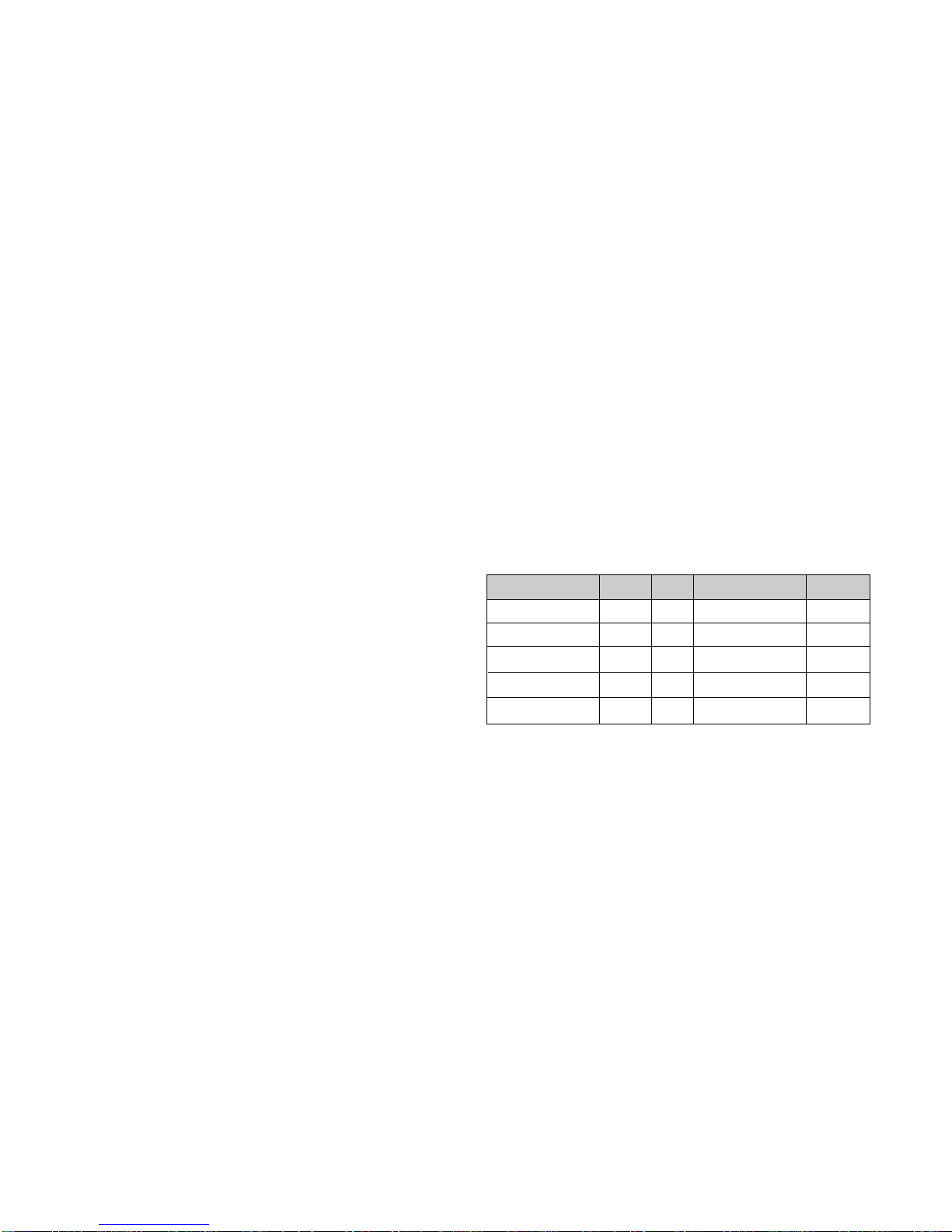
MODE
POWER ON (NORMAL)
STAND-BY
SUSPEND
OFF
POWER OFF
H/V SYNC
ON/ON
OFF/ON
ON/OFF
OFF/OFF
-
POWER CONSUMPTION
less than 30 W
less than 3 W
less than 3 W
less than 3 W
less than 3 W
LED COLOR
GREEN
ORANGE
ORANGE
ORANGE
OFF
VIDEO
ACTIVE
OFF
OFF
OFF
-

- 3 -
WARNING FOR THE SAFETY-RELATED COMPONENT.
• There are some special components used in LCD
monitor that are important for safety. These parts are
marked on the schematic diagram and the
replacement parts list. It is essential that these critical
parts should be replaced with the manufacturer’s
specified parts to prevent electric shock, fire or other
hazard.
• Do not modify original design without obtaining written
permission from LG or you will void the original parts
and labor guarantee.
TAKE CARE DURING HANDLING THE LCD MODULE
WITH BACKLIGHT UNIT.
• Must mount the module using mounting holes arranged
in four corners.
• Do not press on the panel, edge of the frame strongly
or electric shock as this will result in damage to the
screen.
• Do not scratch or press on the panel with any sharp
objects, such as pencil or pen as this may result in
damage to the panel.
• Protect the module from the ESD as it may damage the
electronic circuit (C-MOS).
• Make certain that treatment person’s body are
grounded through wrist band.
• Do not leave the module in high temperature and in
areas of high humidity for a long time.
• The module not be exposed to the direct sunlight.
• Avoid contact with water as it may a short circuit within
the module.
• If the surface of panel become dirty, please wipe it off
with a softmaterial. (Cleaning with a dirty or rough cloth
may damage the panel.)
WARNING
BE CAREFUL ELECTRIC SHOCK !
• If you want to replace with the new backlight (CCFL) or
inverter circuit, must disconnect the AC adapter
because high voltage appears at inverter circuit about
650Vrms.
• Handle with care wires or connectors of the inverter
circuit. If the wires are pressed cause short and may
burn or take fire.
PRECAUTION
CAUTION
Please use only a plastic screwdriver to protect yourself
from shock hazard during service operation.
CAUTION
• There is two backlight, must distinguish between
the top (upper) and the bottom (lower), and be
careful of treatment it.
• MTBF (Mean Time Between Failure) of a backlight
is about 25,000 hours.
Top (Upper) Backlight Ass’y
(P/N: 6913TZZ001D)
Bottom (Lower) Backlight Ass’y
(P/N: 6913TZZ001E)
IF BRIGHTNESS OF THE LCD MODULE DARKEN,
REPLACE THE BACKLIGHT ONE OR ALL.

TIMING CHART
- 4 -
VIDEO
SYNC
B
D
CFE
A
H / V
H (Pixels)
V (Lines)
H (Pixels)
V (Lines)
H (Pixels)
V (Lines)
H (Pixels)
V (Lines)
H (Pixels)
V (Lines)
H (Pixels)
V (Lines)
H (Pixels)
V (Lines)
H (Pixels)
V (Lines)
H (Pixels)
V (Lines)
H (Pixels)
V (Lines)
H (Pixels)
V (Lines)
H (Pixels)
V (Lines)
H (Pixels)
V (Lines)
H (Pixels)
V (Lines)
Sync
Polarity
+
–
–
+
–
–
–
–
–
–
–
–
+
+
+
+
+
+
+
+
–
–
–
–
–
–
+
+
Dot
Clock
25.175
28.322
25.175
30.24
31.5
31.5
36.0
40.0
50.0
49.5
57.2832
65
75
78.75
Frequency
31.468 KHz
70.0 Hz
31.468 KHz
70.0 Hz
31.469 KHz
60.0 Hz
35.00 KHz
66.67 Hz
37.861 KHz
72.8 Hz
37.50 KHz
75.0 Hz
35.156 KHz
56.25 Hz
37.879 KHz
60.3 Hz
48.077 KHz
72.188 Hz
46.875 KHz
75.0 Hz
49.725 KHz
74.55 Hz
48.363 KHz
60.0 Hz
56.476 KHz
70.0 Hz
60.023 KHz
75.0 Hz
Resolution
640 x 350
720 x 400
(TEXT)
640 x 480
640 x 480
640 x 480
640 x 480
800 x 600
800 x 600
800 x 600
800 x 600
832 x 624
(MAC)
1024 x 768
1024 x 768
1024 x 768
Total
Period
( E )
800
449
900
449
800
525
864
525
832
520
840
500
1024
625
1056
628
1040
666
1056
625
1152
667
1344
806
1328
806
1312
800
Video
Active
Time ( A )
640
350
720
400
640
480
640
480
640
480
640
480
800
600
800
600
800
600
800
600
832
624
1024
768
1024
768
1204
768
Blanking
Time
( B )
160
99
180
49
160
45
224
45
192
40
200
20
224
25
256
28
240
66
256
25
320
43
320
38
304
38
288
32
Sync
Duration
( D )
96
2
108
2
96
2
64
3
40
3
64
3
72
2
128
4
120
6
80
3
64
3
136
6
136
6
96
3
Back
Porch
( F )
48
60
55
34
48
33
96
39
128
28
120
16
128
22
88
23
64
23
160
21
224
39
160
29
144
29
176
28
Front
Porch
( C )
16
37
17
13
16
10
64
3
24
9
16
1
24
1
40
1
56
37
16
1
32
1
24
3
24
3
16
1
MODE
1
2
3
4
5
6
7
8
9
10
11
12
13
14

+
OPERATING INSTRUCTIONS
- 5 -
FRONT VIEW REAR VIEW
Front Control Panel
ID Label
Power (DPMS) Indicator
1. Power ON/OFF Button
This button is used to turn the monitor ON and OFF.
2. Power Indicator
This indicator lights up green when the monitor
operates normally; in DPMS (Energy Saving) mode,
-stand-by, suspend, or power off mode -its color
changes to orange.
3. AUTO/SET Button
Use this button to enter a selection in the on screen
display.
* AUTO adjustment function
Touch the AUTO button
before using OSD menu.
This button is for the automatic
adjustment of the screen position, clock and phase.
Note: Some signal from some graphics boards may not function
properly. If the results are unsatisfactory, adjust your
monitor’s Position, Clock and Phase manually.
4. OSD Select/Adjustment Buttons
Use these buttons to choose or adjust
items in the on screen display.
5. OSD Select/Adjustment Buttons
Use this button to enter and from the on screen display
(OSD).
Power ON/OFF Button
Front Control Panel DC Power Connector
D-Sub
Signal Connector
-+
AUTO/SET
5. OSD Button
3. AUTO/SET Button
1. Power ON/OFF Enter Button
2. Power (DPMS) Indicator
4. OSD Select/Adjustment Buttons
AUTO/SET
<Shortcut Keys>
•Brightness and Contrast can be adjusted
directly without entering the On Screen
Display (OSD) system. Touch the
buttons to adjust the settings and then the
OSD button to save all changes. The
Brightness and Contrast functions are also
available in the On Screen Display (OSD)
menu.

- 6 -
On-Screen-Display (OSD) Control
Making adjustments to the image size, position and operating
parameters of the monitor are quick and easy with the On
Screen Display Control system. A quick example is given below
to familiarize you with the use of the controls. Following section
is an outline of the available adjustments and selections you can
make using the OSD.
To make adjustments in the On Screen Display, follow these
steps:
NOTE
Allow the monitor to stabilize for at least 30 minutes before
making image adjustment.
/
AUTO
AUTO
1.
Press the Button, then the main menu of the
OSD appears.
2.
To acces a control, use the Buttons.
When the icon you want becomes highlighted, press
the AUTO Button.
3.
Use the Buttons to adjust
the item to the desired level.
4. Accept the changes by pressing the AUTO Button.
5.
Exit the OSD by Pressing the Button.
Listed below are the icons, icon names, and icon
descriptions of the items that are shown on the Menu.
88
100
BRIGHTNESS CONTRAST
9300K 6500K
COLOR
PRESET
RED
GREEN
BLUE
61
39
POSITION
Brightness
Used to adjust the brightness of the
screen.
Contrast
Adjust the display to the contrast
desired.
PRESET
RED
GREEN
BLUE
9300K/ 6500K
To appear the displays color temperature.
•9300K:Slightly bluish white.
•6500K:Slightly reddish white.
To set your own color levels.
Vertical Position
To move image up and down.
Horizontal Position
To move picture image left and right.
TRACKING
CLOCK
PHASE
LANGUAGE ENGLISH
OSD POSITION
48.3kHz / 60.0Hz
PRESET MODE
SETUP
To minimize any vertical bars or stripes
visible on the screen background.The
horizontal screen size will also change.
To adjust the focus of the display. This item
allows you to remove any horizontal noise and
clear or sharpen the image of characters.
To choose the language in which the
control names are displayed.
To adjust position of the OSD window
on the screen.
LANGUAGE
OSD POSITION
CLOCK
PHASE

- 7 -
CONTROL LOCATIONS
MAIN PCB
CONTROL PCB
1234567
NO.
1
2
3
4
5
6
7
Ref. No.
S9
S3
S4
S5
S6
S7
S8
Control Function
POWER SWITCH
AUTO BUTTON
OSD +
OSD
-
OSD RIGHT
OSD LEFT
OSD ON/OFF
WIRING DIAGRAM
CN1
CN2
P1
P2
J6
CN3
J4
J5
P3

- 8 -
DISASSEMBLY
(a)
1. TILT/SWIVEL REMOVAL
(1) Remove four screws (a).
(2) Remove the Tilt/swivel.
2. BACK COVER REMOVAL
(1) Remove four screws (a) from the Back Cover.
(2) Remove the Back Cover.
3. TOP SHIELD & INVERTER SHIELD REMOVAL
(1) Remove six screws (a).
(2) Remove the Top Shield.
(3) Disconnect P1. (P1: See control Board)
(4) Remove two screws (b).
(5) Release two latchs (c).
(6) Remove the Inverter Shield.
(b)
(b)
(a)
(a)
(a)
(a)
(a)
(c)
(a)
(a)
(a)
Back Cover

- 9 -
5. BACKLIGHT REMOVAL
(1) Remove two screws (a).
(2) Remove the Backlight from the LCD Module.
6. LCD MODULE REMOVAL
(1) Remove four screws (a).
(2) Separate the LCD Module from the Main Frame.
Bottom (Lower) Backlight Ass’y
Top (Upper) Backlight Ass’yLCD Module
(a)
(a)
(a)
(a)
(a)
(a)
(a)
(d)
(d)
(a)(a)
CN2
J6
CN3
J4
J5
(a)
(d)
(b)
(b)
(d)
(c)
(c)
4. INVERTER, POWER, CONTROL, AND MAIN PCB
ASSEMBLY REMOVAL
(1) Disconnect J4, J6 and J5.
(2) Remove four screws (a).
(3) Remove the Main PCB Ass’y.
(4) Disconnect CN2 and CN3.
(5) Remove two screws (b).
(6) Remove the Inverter PCB Ass’y.
(7) Remove two screws (c).
(8) Remove the Control and Power PCB Ass’y.
(9) Remove four screws (d).
(10) Remove the Front Cabinet..

BLOCK DIAGRAM
- 10 -
POWER CORD
15-pin D-SUB SIGNAL CABLE
POWER
SUPPLY
CONTROL PCB
INVERTER PCB
MAIN LOGIC
PCB
LCD MODULE
System Block Diagram

- 11 -
BLOCK DIAGRAM

DESCRIPTION OF BLOCK DIAGRAM
- 12 -
1. Scaler One chip IC(GMZAN1, U3)
GMZAN1 (U3) is one chip IC which it supports four internal function blocks of Video Amp, PLL,
A/D converter and Video processor.
Video signal (0.7Vp.p) clamped through C44, 45, 191 with matching IC’s proper cut off voltage.
This signal is processed as a proper 8 bit digital signal by U3’s amplifying, phase locking, A/D converting,
and scaling operations.
U3 generates Clock, Horizontal and Vertical sync, Data Enable signals as LCD Panel’s input signals.
2. System Controller (Microprocessor) Circuit
1) Microprocessor (U4) distinguishes polarity and frequency by calculating horizontal and vertical sync input
from signal source.
2) Microprocessor (U4) carries out power control by sending power-down trigger signal to each IC.
3) Microprocessor (U4) communicates with EEPROM (U1), and GMZAN1 (U3)
through IIC(2 lines) or 6 bit bus line. It makes all devices operated properly.
4) Microprocessor (U4) let User adjust screen by OSD function.
3. DC/ DC Converter
This circuit supplies DC power for each device needing DC voltage of 3.3VD, 3.3V_AD, 3.3V_PL, and 5VS.
L4973D5.1(U13) , the DC/DC controller IC converts input 24Vdc into 5VS and 3.3Vdc with peripheral circuit
composed of Inductor (L11), condensing components (ZD5, C72), and Regulators(U2, U7, U24).
MODPWR(3.3V) for LCD module power is switched by U12, switching FET, controlled by Microprocessor.
3.3VD, 3.3V_AD, and 3.3V_PL for GMZAN1 (U3) is switched by U5, switching FET, controlled by
Microprocessor for Power saving.

ADJUSTMENT
- 13 -
220
IBM
Compatible PC
PARALLEL PORT
Power inlet (required)
Power LED
ST Switch
Power Select Switch
(110V/220V)
Control Line
Not used
RS232C
PARALLEL
V-SYNC POWER
ST
VGS MONITOR
E
E
V-Sync On/Off Switch
(Switch must be ON.)
F
F
A
A
B
B
C
C
1510
5
569
1
1
1
14
13
25
6
5V
5V
5V
4.7K
4.7K
4.7K
74LS06
74LS06
OFF ON
OFF
ON
11
Figure 1. Cable Connection
All adjustment are thoroughly checked and corrected
when the monitor leaves the factory, but sometimes
several minor adjustment may be required.
Adjustment should be following procedure and after
warming up for a minimum of 10 minutes.
Alignment appliances and tools.
- IBM Compatible PC
- Programmable Signal Generator.
(eg. VG-819 made by Astrodesign Co.)
- E(E)PROM with each mode data saved.
- Alignment Adapter and Software.
1. Adjustment for Factory Preset Mode
1) Run alignment program for LB570F on the IBM
compatible PC.
2) Select EEPROM ALL Init command and Enter.
3) Display cross hatch pattern at Mode 1.
4) Select FOS DEFAULT command and Enter.
5) Press "Y" key, it will automatically save all FOS data
to EEPROM.
2. Adjustment for White Balance
1) Display color 0,0 pattern at Mode 13.
2) Set External Bright to MAX position and Contrast to
MAX Position.
3) Select PRESET START →BIAS CAL command
and Enter.
4) No attempt to manually adjust, BIAS data is auto-
matically adjusted and saved to the EEPROM.
5) Display color 15,0 pattern at Mode 13.
6) Select DRIVE CAL command and Enter.
7) Color 1 (9300K) and Color 2 (6500K) are
automatically adjusted and saved to the EEPROM.
8) Select PRESET EXIT command and Enter.
3. DDC Data Write Procedure
1) Use this procedure only when there is some
probelm on EDID data.
2) Select EEPROM →EDID Write command and
Enter.
3) This will write the EDID data to EEPROM.

- 14 -
TROUBLESHOOTING GUIDE
1. NO POWER
CHECK U4.
CHECK
U4 PIN 8 VOLTAGE
(5V) ?
NO
NO POWER
(POWER INDICATOR OFF)
CHECK ADAPTER,
AND FIND OUT
A SHORT POINT
AS OPENING
EACH POWER LINE
CHECK J1’S
VOLTAGE
(24V) ?
NO
CHECK L11
(OPEN CHECK)
CHECK
U5 Voltage
(5V) ?
NO
U13’S PIN11
0V ?
CHECK U13, AND
CHECK 5VA LINE
CHECK IIC LINE
CONNECTION
(U4, U1)
CHECK U3’S VCC,
XTAL, RESET
IS U3 PIN12
VOLTAGE REPEATED
AS PULSE SHAPE ? NO
YES
YES
YES
NO YES
NO PROBLEM
NO
CHECK KEY CONTROL
CONNECTOR ROUTINE

- 15 -
2. NO RASTER (OSD IS NOT DISPLAYED) – INVERTER
CHECK MICOM INV
ON/OFF PORT.
J4 PIN5
5V? NO
NO RASTER
(OSD IS NOT DISPLAYED)
CHECK ADAPTER
J4 PIN10
24V? NO
1. CONFIRM BRIGHTNESS
OSD CONTRL STATE.
2. CHECK MICOM DIM-ADJ
PORT
J4 PIN1
5V? NO
REPLACE
INVERTER ASS’Y
CHECK
PULSE AS
CONTACTING SCOPE
PROBE TO CAUTION LABEL.
(CONTACT PROBE TO
CAUTION LABEL.
CAN YOU SEE PULSE
AT YOUR
SCOPE?
NO
REPLACE CCFL LAMP
IN THE LCD MODULE
YES
YES
YES
YES

- 16 -
1. CHECK PIN141, 142
SOLDERING CONDITION
2. CHECK X2
3. TROUBLE IN U3
U3
POWER PINS
3.3V?
NO CHECK U2, U24
U3 PIN141, 142
OSCILLATE AS 14.3M? NO
CHECK U5’S SOLDERING
CONDITION AND
CHECK CONNECTION LINE
FROM U3 TO J5
NO
TROUBLE IN CABLE
OR LCD MODULE
CHECK U12, U7
J5 PIN40
3.3V? NO
YES
YES
YES
YES
3. NO RASTER (OSD IS NOT DISPLAYED) – gmzanl
NO RASTER
(OSD IS NOT DISPLAYED)
J5
PIN2 IS 65MHz CLOCK?
PIN4 IS 48KHz H-SYNC?
PIN5 IS 60Hz V-SYNC?
PIN37 IS 48KHz H-SYNC?
IS PULSE APPEARED
AT SIGNAL PINS?

- 17 -
CHECK U2, U24
U3
POWER PIN
3.3V?
NO
1. CHECK PC
2. CHECK SIGNAL CABLE
& D-SUB CONNECTOR
LINE
CHECK
R,G,B INPUT?
U3 PIN 87, 91, 95 NO
CHECK H-SYNC LINE
(D-SUB→U6→MICOM
→U3 PIN150)
CHECK
H-SYNC INPUT
U3 PIN 150?
NO
YES
YES
YES
YES
NO RASTER
(OSD IS DISPLAYED)
4. NO RASTER (OSD IS DISPLAYED) – gmzanl
CHECK SIGNAL LINE
FROM U1 PIN84
TO U4 PIN254
(1024x768/85Hz : 95MHz)
CHECK
CLOCK INPUT
(25MHz-95MHz SINEWAVE)?
U5 PIN207
NO
CHECK SIGNAL LINE
FROM U2 PIN80
TO U5 PIN203
CHECK
H-SYNC INPUT?
U5 PIN203
NO
YES

PRINTED CIRCUIT BOARD
- 18 -
41
C197
C227
40
C195
MODEL:LB570F
P/N :6870T291A10
DATE :2000.11.07
U7
C90
L7
C88
C137
2
1
L8
L9
R54
80
BA20BA19
70
BA22
BA21
60
50
L2
BA24
BA23
40
U12
R81
J5
C89
90
R1
C1
C46
C49
30
R79
D5D6
R5
100
R53
20
R95
R94
R96
D3 D2
R98
R97
R99
C70
R6R7
C23
110
U3
10
5
R2
D4
R29
D1
U2
120
130
150
140 160
R28
ZD1 ZD2
C48
R91
X2
R37 C17 C19
R55
R9
R64
C59
U6
L3
L4
C71
J6
U24
C28
RA1
R50
C131
C26
R12
R11
C10
RA2
R78
U1
R4
L5
L6
R8
C12
C14
J3
U5
C72
R52
R74
R80
R82
R3
R60
J1
C6
J2
L11
C239 R87
C238
R51
X1
R10
R38
C237 R15
R13
C135
ZD5
U13
C64
C37 C38
U4
Q1
U8
C236 R86
1
J4
C188
1. MAIN BOARD (Component Side)

- 19 -
2. MAIN BOARD (Solder Side)

- 20 -
EXPLODED VIEW
12
4
3
8
9
10
11
12
13
14
15
5
6
7
MODULE
This manual suits for next models
1
Table of contents
Other LG Monitor manuals