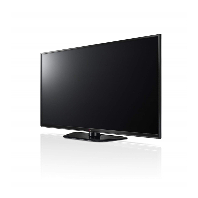
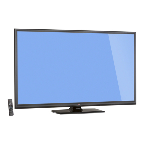
LG 50PB2DR Series User manual

PLASMA TV
SERVICE MANUAL
CAUTION
BEFORE SERVICING THE CHASSIS,
READ THE SAFETY PRECAUTIONS IN THIS MANUAL.
CHASSIS : PB61C
MODEL : 50PB2DR
50PC2DR-AC
website:http://biz.LGservice.com
e-mail:http://www.LGEservice.com/techsup.html

- 2 -
CONTENTS
SAFETY PRECAUTIONS ....................................................................................3
DESCRIPTION OF CONTROLS ..........................................................................4
SPECIFICATIONS ................................................................................................9
ADJUSTMENT INSTRUCTIONS .......................................................................12
BLOCK DIAGRAM & TROUBLE SHOOTING GUIDE ......................................19
EXPLODED VIEW..............................................................................................44
EXPLODED VIEW PARTS LIST ........................................................................45
REPLACEMENT PARTS LIST...........................................................................46
SCHEMATIC DIAGRAM.........................................................................................
PRINTED CIRCUIT DIAGRAM ..............................................................................

- 3 -
SAFETY PRECAUTIONS
Many electrical and mechanical parts in this chassis have special safety-related characteristics. These parts are identified by in the
Schematic Diagram and Replacement Parts List.
It is essential that these special safety parts should be replaced with the same components as recommended in this manual to prevent
X-RADIATION, Shock, Fire, or other Hazards.
Do not modify the original design without permission of manufacturer.
General Guidance
An isolation Transformer should always be used during the
servicing of a receiver whose chassis is not isolated from the AC
power line. Use a transformer of adequate power rating as this
protects the technician from accidents resulting in personal injury
from electrical shocks.
It will also protect the receiver and it's components from being
damaged by accidental shorts of the circuitry that may be
inadvertently introduced during the service operation.
If any fuse (or Fusible Resistor) in this monitor is blown, replace it
with the specified.
When replacing a high wattage resistor (Oxide Metal Film Resistor,
over 1W), keep the resistor 10mm away from PCB.
Keep wires away from high voltage or high temperature parts.
Due to high vacuum and large surface area of picture tube,
extreme care should be used in handling the Picture Tube.
Do not lift the Picture tube by it's Neck.
Leakage Current Cold Check(Antenna Cold Check)
With the instrument AC plug removed from AC source, connect an
electrical jumper across the two AC plug prongs. Place the AC
switch in the on position, connect one lead of ohm-meter to the AC
plug prongs tied together and touch other ohm-meter lead in turn to
each exposed metallic parts such as antenna terminals, phone
jacks, etc.
If the exposed metallic part has a return path to the chassis, the
measured resistance should be between 1MΩand 5.2MΩ.
When the exposed metal has no return path to the chassis the
reading must be infinite.
An other abnormality exists that must be corrected before the
receiver is returned to the customer.
Leakage Current Hot Check (See below Figure)
Plug the AC cord directly into the AC outlet.
Do not use a line Isolation Transformer during this check.
Connect 1.5K/10watt resistor in parallel with a 0.15uF capacitor
between a known good earth ground (Water Pipe, Conduit, etc.)
and the exposed metallic parts.
Measure the AC voltage across the resistor using AC voltmeter
with 1000 ohms/volt or more sensitivity.
Reverse plug the AC cord into the AC outlet and repeat AC voltage
measurements for each exposed metallic part. Any voltage
measured must not exceed 0.75 volt RMS which is corresponds to
0.5mA.
In case any measurement is out of the limits specified, there is
possibility of shock hazard and the set must be checked and
repaired before it is returned to the customer.
Leakage Current Hot Check circuit
1.5 Kohm/10W
To Instrument's
exposed
METALLIC PARTS
Good Earth Ground
such as WATER PIPE,
CONDUIT etc.
AC Volt-meter
IMPORTANT SAFETY NOTICE
0.15uF

OK
TVD/A
INPUT
INPUT
BRIGHT
MODE
DVD
ARC
EXIT
VOL
SIZE
INDEX
TIME
REVEAL
I/II
ADJUST
APM
Q.VIEW
MUTE
PR
MARK
MENU
LIVE TV
TEXTPIP
GUIDE
INFO
VCR
POWER
123
456
789
0
FAVLIST
?
PIP PR- PIP PR+
PIP INPUTSWAP
PAGE
SLEEP
TIME
SHIFT
TIME
SHIFT
Selects digital or analogue mode.
External input modes rotate in regular sequence:
Digital, Analogue, AV1-2, Component 1-2, RGB-
DTV (or RGB-PC), HDMI1/DVI, HDMI2.
Switches the set between ON and STANDBY.
Selects your desired picture format.
Adjusts brightness on screen.
It returns to the default settings brightness by
changing mode source.
Use for DVR record or trick play.
Controls the mode.
For further details, see the DVR section.
Control some video cassette recorders or DVD players
("RECORD" button is not available for DVD player).
Accepts your selection or displays the current mode.
Adjusts menu settings.
Selects menu item.
Increase/decrease the sound level.
Returns to the previously viewed programme.
Switches the sound on or off.
Selects a programme.
Move from one full set of screen information to the next one.
Displays the programme list.
Displays the selected favourite programmes.
Selects the sound output or the audio mode.
Concurrently, compare with the Dynamic, Standard,
Mild, User1 and User2 on the screen.
Sets the sleep timer.
Adjust the screen Resolution, position, clock, and phase.
D/A INPUT
(Digital TV /
Analogue TV)
INPUT
POWER
ARC
+/-
OK
THUMBSTICK
(Up/Down/Left
Right/OK)
VOLUME +/-
Q.VIEW
MUTE
PROGRAMME +/
-
PAGE UP/DOWN
LIST
FAV (FAVOURITE)
I/II
APM
SLEEP
ADJUST
NUMBER button
VCR/DVD
control buttons
mode control
buttons
1
- 4 -
DESCRIPTION OF CONTROLS

- 5 -
n
Open the battery compartment cover on the
back side and install the batteries matching
correct polarity (+with +,-with -).
n
Install two 1.5V AA batteries. Don’t mix old or
used batteries with new ones.
n
Close cover.
n
Use a remote control up to 7 meters distance
and 30 degree (left/right) within the receiving
unit scope.
n
Dispose of used batteries in a recycle bin
to preserve environment.
TVD/A
INPUT
INPUT
BRIGHT
MODE
DVD
ARC
TEXTPIP
GUIDE
INFO
VCR
POWER
PIPPR- PIP PR+
PIPINPUTSWAP
R
TVD/A
INPUT
INPUT
BRIGHT
MODE
DVD
ARC
TEXTPIP
GUIDE
INFO
VCR
POWER
PIPPR- PIP PR+
PIPINPUTSWAP
Installing Batteries Remote control effective range
TV, VCR, DVD
,
GUIDE
INFO
PIP
PIP PR +/-
SWAP
PIP INPUT
COLOURE
Button
EXIT
MENU
LIVE TV
MARK
TELETEXT
BUTTONS
Selects the remote operating mode: TV, VCR, DVD. Select other operating mode
for the remote to operate external devices.
Shows a programme schedule.
Shows the present screen information.
Switches to PIP, POP and Twin picture modes or off mode.
Selects a programme for the sub picture.
Alternates between main and sub picture in PIP/Twin picture mode.
Selects the input mode for the sub picture.
They are used as per the indications or functions displayed on the TV screen in
the case of Text displays (Teletext, EPG) and programme edit.
Returns to TV viewing from any menu.
Selects a menu.
Enter to the mode.
When playing the recorded program: Return to the last selected input source.
When delaying: Return to the last selected input source.
Selects the wanted functions.
These buttons are used for teletext.
Text button is used to enable teletext services while other buttons are for teletext
functions.
* For further details, see the ‘Teletext’section.
1

- 6 -
Front Panel Controls
PR
VOL
OK
MENU
INPUT
PR
PR
VOL
VOL
OK
OK
MENU
MENU
INPUT
INPUT
(POWER) Button
INPUT Button
MENU Button
OK Button
VOLUME (FF,GG)
Button
PROGRAMME
(DD,EE)Button
Remote Control Sensor
PR
VOL
OK
MENU
INPUT
Power Standby Indicator
Illuminates red in standby mode.
When the TV is turned on, the indicator
blinks white and then illuminates white
before the picture is displayed.
INDEX
Digital, Analogue
Component mode
AV mode
HDMI1/DVI or HDMI2 mode
PR
VOL
OK
MENU
INPUT
PR
VOL
OK
MENU
INPUT
PR
VOL
OK
MENU
INPUT
PR
VOL
OK
MENU
INPUT

- 7 -
Back Connection Panel
HDMI IN
DIGITAL AUDIO
OUT
OPTICAL
RS-232C IN
(CONTROL & SERVICE)
RGB (PC/DTV)
RGB IN
AUDIO (RGB/DVI)
2
1 (DVI)
COMPONENT IN
VIDEO
AUDIO
VIDEO
AUDIO
( )
S-VIDEO
AV IN 1
AV OUT
ANTENNA
IN
REMOTE
CONTROL IN
S-VIDEOVIDEO AUDIO
AV IN 2
L/MONO R
HDMI INHDMI IN
DIGITAL AUDIODIGITAL AUDIO
OUTOUT
OPTICALOPTICAL
RS-232C INRS-232C IN
(CONTROL & SERVICE)(CONTROL & SERVICE)
RGB (PC/DTV)RGB (PC/DTV)
RGB INRGB IN
AUDIO (RGB/DVI)AUDIO (RGB/DVI)
2
1 (DVI)
1 (DVI)
COMPONENT INCOMPONENT IN
VIDEOVIDEO
AUDIOAUDIO
VIDEOVIDEO
AUDIOAUDIO
MONO
()
S-VIDEOS-VIDEO
AV IN 1AV IN 1
AV OUTAV OUT
ANTENNAANTENNA
ININ
REMOTEREMOTE
CONTROL INCONTROL IN
AUDIO Input
Connections are available for listen-
ing to stereo sound from an external
device.
VIDEO Input
Connects the video signal from a
video device.
AV OUT
Connect a second TV or monitor.
AV (Audio/Video) IN 1
Connect audio/video output from an external
device to these jacks.
S-VIDEO
Connect S-Video out from an S-VIDEO device.
COMPONENT IN
Connect a component video/audio device to
these jacks.
HDMI IN
Connect a HDMI signal.
Or DVI(VIDEO)signal to the this port with a
HDMI to DVI cable.
DIGITAL AUDIO OUT OPTICAL
Connect digital audio from various types of
equipment. Note: In standby mode, these
ports do not work.
RS-232C IN (CONTROL &SERVICE) PORT
Connect to the RS-232C port on a PC.
ANTENNA IN
Connect cable signals to this jack.
RGB/AUDIO IN
Connect the output from a set-top box or PC
to the appropriate input port.
Remote Control Port
Connect your wired remote control.
Power Cord Socket
For operation with AC power.
Caution: Never attempt to operate the TV on
DC power.
10
1
2
4
16
7
8
9
9
10
2
3
4
5
5 6
7
8
3
9
10

- 8 -
Owner’s Manual
1.5V 1.5V
Owner’s Manual Batteries
OK
TVD/A
INPUT
INPUT
BRIGHT
MODE
DVD
ARC
EXIT
VOL
SIZE
INDEX
TIME
REVEAL
I/II
SLEEP
ADJUST
APM
Q.VIEW
MUTE
PR
MARK
MENU
LIVETV
TEXTPIP
GUIDE
INFO
VCR
POWER
123
456
789
0
FAVLIST
?
PIPPR- PIP PR+
PIPINPUTSWAP
PAGE
TIME
SHIFT
TIME
SHIFT
Remote Control Power Cord
For 50PB2DR
2-Wall brackets 2-eye-bolts
Polishing Cloth
Polish the screen with the cloth.
*
Slightly wipe stained spot on the exterior only with
the cleansing cloths for the product exterior if there
is stain or fingerprint on surface of the exterior.
* Do not wipe roughly when removing stain. Please
be cautions of that excessive power may cause
scratch or discoloration.
Accessories

SPECIFICATIONS
NOTE : Specifications and others are subject to change without notice for improvement
.
VApplication Range
This spec is applied to the 50”PLASMA TV used PB61C Chassis.
V Specification
Each part is tested as below without special appointment.
1) Temperature : 25±5°C (77±9°F), CST : 40±5
2) Relative Humidity: 65±10%
3) Power Voltage: Standard Input voltage (100-240V~, 50/60Hz)
* Standard Voltage of each product is marked by models.
4) Specification and performance of each parts are followed each drawing and specification by part number in accordance with SBOM.
5) The receiver must be operated for about 20 minutes prior to the adjustment.
VTest Method
1) Performance : LGE TV test method followed.
2) Demanded other specification
Safety : IEC60065 specification
EMC : CISPR 13 specification
VGeneral Specification
1. Model General Specification
- 9 -
Chassis
PB61C 50PB2DR-AC Australia LG
Model Name Market Brand Remark
50PB2DR-AC Safety : IEC60065,EN60950
EMC : CISPR 13,EN55020,EN/IEC61000-3-2 and 3
Australia
Model ApplianceMarket Remark
Broadcasting system
Available Channel
Tuner IF
Input Voltage
PDP Module
Aspect ratio
Operating Temperature
Operating Humidity
Storage Temperature
Storage Humidity
PAL-B/G, DTV : DVB-T
1) VHF : 00 ~ 12
2) UHF : 20 ~ 75
3) CATV : 02 ~ 44
4) DTV : 06 ~12, 27 ~ 69
1) PAL : 38.90MHz(Picture),
34.40MHz(Sound)
2) DVB-T : 36.125MHz
240V~, 50Hz
PDP50X3
16:9 (wide)
0 40 deg
85 %
-20 60 deg
85 %
1
2
3
4
5
6
7
8
9
10
No Item
Remark
Maker : LGE
LGE 50”
Specification
Min Typ Max Unit

- 10 -
White peak brightness
White average brightness
Brightness uniformity
WHITE X
Y
Color coordinate uniformity
Contrast ratio at dark room
Contrast ratio at office room
Power Consumption
850
170
-10
0.285
0.285
-0.010
5000:1
40:1
1000
200
0
0.300
0.300
Ave.
10000:1
50:1
370
10
0.315
0.315
+0.010
400
1
2
3
4
5
6
7
8
9
No Item Remark
1% white window
Full white
Full white
Full White
cd/m2
cd/m2
%
W
Min Typ Max Unit
Display area
Outline dimension
Number of Pixels
Cell pitch
Pixel type
Weight(net)
Weight(gross)
Operation Environment Temperature
Humidity
Pressure
Storage Environment Temperature
Humidity
Pressure
I mage stick minimization Start time
mode Low Brightness
Arrival Time
1106.5(H) * 622.1(V) ° ±0.5
1190(H) * 700(V)*58(D) ° ±1
1366(H) * 768(V)
270(H) *810(V)
RGB Closed type (well)
20.9 21.4 21.9
122.0 127.0 132.0
0 ~ 40
20 ~ 80
800 ~ 1100
-20 ~ 60
10 ~ 90
700 ~ 1100
4.5 5 5.5
14 15 16
1
2
3
4
5
6
7
8
9
10
No Item Remark
1Pixel=3RGB Cells
1Pixel=3RGB Cells
5EA 1Box
Altitude : 0 to 2000M
mm
mm
um
Kg
Kg
deg
%
hPa
deg
%
hPa
min
min
Min Typ Max Unit
2. Module Specification ( PDP50X3 )
2-1. General Specification
2-2. Electro Optical Characteristic Specifications

- 11 -
White peak brightness
White average brightness
Brightness uniformity
WHITE X
Y
Color coordinate uniformity
Contrast ratio at dark room
Contrast ratio at office room
Power Consumption
1,000
170
-10
0.295
0.295
-0.010
5,000:1
90:1
1,500
200
0
0.310
0.310
Ave.
15,000:1
130:1
380
10
0.325
0.325
+0.010
400
1
2
3
4
5
6
7
8
9
No Item Remark
1% white window
Full white
Full white
Full White
cd/m2
cd/m2
%
W
Min Typ Max Unit
Display area
Outline dimension
Number of Pixels
Cell pitch
Pixel type
Weight(net)
Weight(gross)
Operation Environment Temperature
Humidity
Pressure
Storage Environment Temperature
Humidity
Pressure
I mage stick minimization Start time
mode Low Brightness
Arrival Time
1106.5(H) * 622.1(V) ° ±0.5
1190(H) * 700(V)*52(D) ° ±1
1366(H) * 768(V)
270(H) *810(V)
RGB Closed type (well)
19.7 20.2 20.7
278.7 279.2 279.7
0 ~ 40
20 ~ 80
800 ~ 1100
-20 ~ 60
10 ~ 90
700 ~ 1100
4.5 5 5.5
14 15 16
1
2
3
4
5
6
7
8
9
10
No Item Remark
1Pixel=3RGB Cells
1Pixel=3RGB Cells
5EA 1Box
Altitude : 0 to 2000M
mm
mm
um
Kg
Kg
deg
%
hPa
deg
%
hPa
min
min
Min Typ Max Unit
3. Module Specification ( PDP50X4 )
3-1. General Specification
3-2. Electro Optical Characteristic Specifications

- 12 -
ADJUSTMENT INSTRUCTIONS
1. Application Object
These instructions are applied to all of the 50”PLASMA TV,
PB61C
Chassis
2. Notes
(1) Because this is not a hot chassis, it is not necessary to use
an isolation transformer. However, the use of isolation
transformer will help protect test equipment.
(2) Adjustments must be done in the correct order.
(3) The adjustments must be performed in the circumstance of
25±5°C of temperature and 65±10% of relative humidity if
there is no specific designation.
(4) The input voltage of the receiver be must kept 220V~,
60Hz when adjusting.
(5) The receiver must be operational for about 15 minutes
prior to the adjustments.
OPreliminary action is applied to the test for afterimage
discharge detection, and 100% FULL WHITE PATTERN
must be operated automatically.
OTest for afterimage discharge detection
1) After pressing Power Only key(only operating by
pressing Power Only key), Full Test Pattern(2 min
30sec) --> Full Black Pattern(30sec) --> After this state,
Full White Pattern is displayed.
(but you must preset the program for Full White State
when you press the Main Power Off/On)
2) Pattern Mode is deselected by pressing CH +/-, Exit Key.
[Set is activated HEAT-RUN without signal generator in
this mode.
If you turn on a still screen more than 20 minutes (Especially
Digital pattern, Cross Hatch Pattern), an afterimage may occur
in the black level part of the screen.
3. CPLD Download
(1) Test Equipment: PC, Jig for download
(2) Connect the power of VSC B/D.
(3) Execute download program of PC.
(4) After executing the hot key on the Programmer, click icon.
(5) End after confirming.
4. Sub-ucom(MTV416) Download
(1) Test Equipment: PC, Jig for download
(2) Connect the power of VSC B/D.
(3) Execute download program of PC.
(4) After executing the hot key on the Programmer, click icon.
(5) End after confirming.
5. MST3361M-Set Adjustment
5-1. Synopsis
MST3361M-Set adjustment to set the black level and the Gain
of optimum with an automatic movement from the analog =>
digital converter.
5-2. Test Equipment
Service R/C, 801GF(802B,802F,802R),
MSPG-925 Pattern Generator.
( 480i, 1080i 60Hz Color Bar Pattern output will be possible
and the output level will accurately have to be revised with
0.7±0.1Vp-p)
5-3. Adjustment
(1) How to adjustment the Component1 480i
60Hz Mode.
1) Select Component1 as the input with Color Bar Pattern
in 480i 60Hz mode and select ‘Component1’on screen.
2) After receiving signal for at least 1 second, press the
ADJ Key on the Service R/C to enter the ‘Ez - Adjust’
and select the ‘2. ADC 480i Comp1’. Pressing the Vol+
Key to adjust the component1.
3) When the adjustment is over, 'ADC Component1
Success’is displayed. If the adjustment has errors,
'ADC Configuration Error’is displayed.
4) Readjust after confirming the case Pattern or adjustment
condition where the adjustment had errors.
5) After adjustment is complete, exit the adjustment mode
by pressing the ADJ KEY.
(2) How to adjustment the Component1 1080i
60Hz Mode, RGB
1) Select Component1, RGB-DTV as the input with Color
Bar Pattern in 1080i 60Hz mode and select
‘Component1’on screen.
2) After receiving signal for at least 1 second, press the
ADJ Key on the Service R/C to enter the ‘Ez - Adjust’
and select the ‘3. ADC 1080i Comp1/RGB’. Pressing
the Vol+ Key to adjust the component1.
3) When the Component1 adjustment is over, 'ADC
Component1 Success’is displayed. and when the RGB
adjustment is over, 'ADC RGB_DTV Success’is
displayed. If the adjustment has errors, 'ADC
Configuration Error’is displayed.
4) Readjust after confirming the case Pattern or adjustment
condition where the adjustment had errors.
5) After adjustment is complete, exit the adjustment mode
by pressing the ADJ KEY.
PC
VSC
B/D
JIG cable(CPLD D/L )
<Fig. 1> Connection Diagram of CPLD Download
(Fig. 2) Adjust Pattern : 480i, 1080i 60Hz Color Bar Pattern

- 13 -
6. Video(uPD)- Set Adjustment
6-1. Synopsis
This is a adjustment to reduce the color difference of video
signal Main/Sub Display.
6-2. Required Equipment
Service R/C, MSPG-925 Pattern Generator.
(It’s available to output the Color Bar Pattern of the NTSC,PAL)
6-3. Adjustment
(1) How to adjustment the uPD PAL
1) Select AV1 as the input with 100% 8 Color Bar Pattern
in PAL mode and select ‘AV1’on screen.
2) After receiving signal for at least 1 second, press the
ADJ Key on the Service R/C to enter the ‘Ez - Adjust’
and select the ‘4. uPD PAL AV(Main&Sub)-Set’.
Pressing the Vol+ Key to adjust the uPD PAL.
3) When the adjustment is over, 'PAL-AV uPD ADC
Success’is displayed. If the adjustment has errors,
'Video Configuration Error’is displayed.
4) Readjust after confirming the case Pattern or adjustment
condition where the adjustment had errors.
5) After adjustment is complete, exit the adjustment mode
by pressing the ADJ KEY.
(2) How to adjustment the uPD NTSC
1) Select AV1 as the input with 100% 8 Color Bar Pattern
in NTSC mode and select ‘AV1’on screen.
2) After receiving signal for at least 1 second, press the
ADJ Key on the Service R/C to enter the ‘Ez - Adjust’
and select the ‘5. uPD NTSC AV(Main&Sub)-Set’.
Pressing the Vol+ Key to adjust the uPD NTSC.
3) When the adjustment is over, 'NTSC-AV uPD ADC
Success’is displayed. If the adjustment has errors,
'Video Configuration Error’is displayed.
4) Readjust after confirming the case Pattern or adjustment
condition where the adjustment had errors.
5) After adjustment is complete, exit the adjustment mode
by pressing the ADJ KEY.
(3) How to adjustment the uPD RF-PAL
1) Input the PAL signal to Set antenna terminal, and select
input mode in ANALOG, and than verify if RF image
appears on screen.
2) After receiving signal for at least 1 second, press the
ADJ Key on the Service R/C to enter the ‘Ez - Adjust’
and select the ‘5. uPD NTSC AV(Main&Sub)-Set’.
Pressing the Vol+ Key to adjust the uPD NTSC.
3) When the uPD RF adjustment is over, appears a
massage as‘AUS RF uPD ADC Success’. If uPD RF
adjustment has errors, can appear 2 kinds of message,
if appears‘Check the signal status’, it means the
signal is not connected correctly, and verify if the signal
is connected correctly to the terminal of Set antenna. If
appears‘Video Configuration Error’, it means the
signal is connected correctly but the adjustment process
was wrong.
4) Readjust after confirming the case Pattern or adjustment
condition where the adjustment had errors.
5) After adjustment is complete, exit the adjustment mode
by pressing the ADJ KEY.
7. POWER PCB Assy Voltage
Adjustment (Va, Vs Voltage Adjustment)
7-1. Test equipment: D.M.M 1EA
7-2. Connection Diagram for Measuring
Refer to Fig.5
7-3. Adjustment Method
Adjustment Method for Power Board( P/No: 6709900020B)
(1) Va Adjustment
1) After receiving 100% Full White Pattern, HEAT RUN.
2) Connect + terminal of D.M.M to Va pin of P805, connect
- terminal to GND pin of P805.
3) After turning VR901, voltage of D.M.M adjustment as
same as Va voltage which on label of panel right/top.
(Deviation; ±0.5V)
(2) Vs Adjustment
1) Connect + terminal of D.M.M to Vs pin of 805, connect –
terminal to GND pin of P805.
2) After turning VR951, voltage of D.M.M adjustment as
same as Va voltage which on label of panel right/top.
(Deviation; ±0.5V)This is the function that enables “Plug
and Play".
(3) 3.3V Adjustment
1) Connect + terminal of D.M.M to Vs pin of 803, connect –
terminal to GND pin of P803.
2) Move UR221 to set the voltage value of D.M.M between
3.36V and 3.4V.
(Fig. 3) Adjust Pattern :100% 8 Color Bar Pattern
Each PCB Assy must be checked by Check JIG Set before
assembly. (Especially, be careful Power PCB Assy which can
cause Damage to the PDP Module.)
(Fig. 5) Connection Diagram of Power Adjustment for Measuring

- 14 -
8. EDID(The Extended Display
Identification Data)/DDC
(Display Data Channel) Download
8-1. Required Test Equipment
(1) PC, Jig for adjusting DDC.
(PC serial to D-sub Connection equipment)
(2) DVI to HDMI Connector.
8-2. Setting of Device
8-3. EDID DATA
<EDID Checksum >
- 50PB2DR-AC
HDMI PORT1 : 61 45
HDMI PORT2 : E6 18
RGB : DB
(1) HDMI/DVI Port1 EDID DATA.
(2) HDMI Port2 EDID DATA.
(3) RGB EDID DATA.
8-4. Act or set the EDID S/W
(1) As above Fig. 6, Connect the Set, EDID Download Jig, PC
& Cable.
(2) Turn on the PC & EDID Download Jig. And Execute the
S/W : EDID TESTER Ver,2.5.
(3) Set up S/W option.
Repeat Number : 3
Device Address : A0
PageByte : 8
PC
JIG
PDP
SET
61
45
DBDB
E6
18
Analog EDID
D-sub to D-sub
HDMI EDID
DVI-D to HDMI

- 15 -
8-5. How to use the EDID S/W
(1) Init the data.
(2) Load the EDID data.(Open File)
(3) Press the “Write Data & Verify”button. and input the data.
(4) If the writing is finished, you will see the “OK”message.
9. Adjustment of White Balance
9-1. Required Equipment
(1) Color analyzer : CA-100+ (CH10) or CA-100 (CH10)
: When adjust the color temperature of Plasma, the Color
analyzer (CA-100+, CA-100) must use channel 10 that is
adjusted in Matrix adjusted by CS-1000 (White, Red,
Green, Blue adjusted) and adjust according to white
balance coordinates as below.
(2) Automatic adjustor (with automatic adjustment hour
necessity and the RS-232C communication being possible)
9-2. Connection Diagram of Equipment
for Measuring (Automatic Adjustment)
(1) Connection Diagram
: Adjusted W/B using inside Pattern. When connecting to
Auto-controller, or pressing R/C ADJ to enter to Ez Adjust
8.White-Balance appears the Pattern automatically.
(2) Condition for automatic adjustment and attentions
1) Apply the adjustment where the illuminance is less than
10 lux, it means in a place controlled in maximum the
indraft of light.
2) Adjust/measure with the Color Analyzer ( CA-100+, CA-
100 ) contacting completely in the surface of Module.
(3) Aging time
1) After Aging start, make Heat-run more than 15 min. (in
power on status)
2) In case of PDP, maintain Full white Pattern using
internal pattern.
(4) Process of automatic adjustment
1) As using the white pattern for adjustment the inner part,
HDMI connection need not. But as lower part, the RS-
232C Command is used.
Wb 00 00 Automatic adjustment of white balance start.
Wb 00 10 The start of gain adjustment.(inside pattern)
Ja 00 ff Adjustment Date.
Jb 00 c0
...
Wb 00 1f The end of gain adjustment.
As occasion demands , adjust the offset.
( Wb 00 20(Start) , Wb 00 2f(end))
Wb 00 ff Automatic adjustment of white balance end.
(Disappear the inside pattern)
[[Caution)RS-232C Command (Automatic Adjustment)
9-3. Adjustment of White Balance
(Automatic Adjustment)
(1) Color analyzer : CA-100+ (CH10) or CA-100 (CH10)
: When adjust the color temperature of Plasma, the Color
analyzer (CA-100+, CA-100) must use channel 10 that is
adjusted in Matrix adjusted by CS-1000 (White, Red,
Green, Blue adjusted) and adjust according to white
balance coordinates as below.
(Inside Pattern)
<Fig. 6> Connection Diagram of Automatic Adjustment
R Gain
G Gain
B Gain
R Offset
G Offset
B Offset
CENTER
(DEFAULT)(Hex)
00
00
00
C0
C0
C0
Min
Max
(Hex)
40
40
40
Cool
40
40
40
Mid
40
40
40
Warm
RS-232C COMMAND
[CMD ID DATA]
Jg
Jh
Ji
Cool
Ja
Jb
Jc
Mid
Jd
Je
Jf
Warm

- 16 -
9-4. Adjustment of White Balance
(Passivity Adjustment)
(1) Enter to ‘EZ-ADJUST’by pressing ADJ key of R/C.
(2) HEAT RUN at least 30 minutes by pressing the ‘11. TEST
Pattern’on the Service Remote Control and adjust.
(3) Set CA-100+ (CH 10) OR CA-100 (CH 10) in Zero
Calibration, when adjust PDP module make it contacting
completely in the surface.
(4) Select ‘8. White-Balance’of ‘Ez - Adjust’by pressing the
ADJ KEY on the Service R/C. Then enter adjustment mode
by pressing the Right KEY (
G
). This time white pattern is
displayed. (When press
G
key, the screen enters to Full
White internal pattern.)
(5) The adjustment completes in three color temperatures as
Cool, Medium, and Warm. ( R/G/B OFFSET=64 fix)
1) When R GAIN is fixed at 192:
keep G GAIN and B GAIN less than 192 and find proper
values for adjustment.
2) When G GAIN is fixed at 192:
keep R GAIN and B GAIN less than 192 and find proper
values for adjustment.
3) When B GAIN is fixed at 192:
keep R GAIN and G GAIN less than 192 and find proper
values for adjustment.
(6) Adjust using Volume +/- KEY.
Value of bright : High Level -> 216gray
[Cool]
Color coordinates : X; 0.277 ± 0.002 Y; 0.281 ± 0.002
Color temperature : 11000°K uv: 0.000
[Medium]
Color coordinates : X; 0.286 ± 0.002 Y; 0.291 ± 0.002
Color temperature : 9300°K uv: 0.000
[Warm]
Color coordinates : X; 0.315 ± 0.002 Y; 0.322 ± 0.002
Color temperature: 6500°K uv: 0.000
(7) Move the the Ez-Adjust screen by pressing the VKEY
and exit the adjustment mode by pressing the ADJ KEY.
[Ref.] White Balance Adjustment Pixel and Color Temperature
(1) When CS-1000 is available:
(2)
CA-210 indication value (CH 10)
(3)
CA-100/100+ indication value (CH 10)
10. How to Download Software
- How to Use RS-232C to Download S/W via Serial port.
10-1. S/W Download Program
(1) Use DTV Lab.
10-2.
Set up the Network Configuration of
the Program for successful download.
(1) Click “Set Property”and set the values as shown in the
following picture.
(2) Set Com Port to Serial Port and Baud Rate to 115200.
(3) Press OK to exit the Configuration.
(4) Connect PC and DTV via Serial Port and turn on the TV.
(5) Press “Connect”. The button will change to “Disconnect.”
Put cursor on the DTV Lab window and press Keyboard to
see the input appear in the window. If it works, the DTV is
successfully connected to computer.
COOL
MIDIUM
WARM
T=11000K, uv: 0.000
T= 9300K, uv: 0.000
T= 6500K, uv: 0.000
x=0.276 y=0.283
x=0.285 y=0.293
x=0.314 y=0.324
Color Temperature Color Coordinate
Color Temperature
Color Coordinate
Measuring instrument
xy
0.283±0.002
0.293±0.002
0.324±0.002
0.276±0.002
0.285±0.002
0.314±0.002
COOL
MIDIUM
WARM
11000
°
K, uv: 0.000
9300
°
K, uv: 0.000
6500
°
K, uv: 0.000
Color Temperature
Color Coordinate
Measuring instrument
xy
0.283±0.002
0.293±0.002
0.324±0.002
0.276±0.002
0.285±0.002
0.314±0.002
COOL
MIDIUM
WARM
11000
°
K, uv: 0.000
9300
°
K, uv: 0.000
6500
°
K, uv: 0.000
[ 50X3, 40%filter ]
Color Temperature
Color Coordinate
Measuring instrument
xy
0.281±0.002
0.291±0.002
0.322±0.002
0.276±0.002
0.285±0.002
0.314±0.002
COOL
MIDIUM
WARM
11000
°
K, uv: 0.000
9300
°
K, uv: 0.000
6500
°
K, uv: 0.000
[ 50X4, 41%filter ]

- 17 -
10-3. Steps to Download S/W
(1) Insert PASSWORD of the model in the activated window.
(Do not insert password for 50PB2DR-AC for which
password is not assigned.)
(2) Press ‘d’to open Debug Main Menu.
(3) Input f0 and then 1.
(4)
Select a program from the following window to download S/W.
(5) Go to the folder where the file is and check the name and
extension of the file. Then, select the file and click “Open”.
(Find an ‘****.epk’file which you want to download and
select it.)
(6) The download process is shown. (It takes around 5
minutes to finish downloading S/W.)
(7) Once the Programming Flash process is successfully
finished, TV Set automatically reboots.
* Check the version of the downloaded file and press
INSTOP. (when the version is incorrect, you need to
download the correct one)
10-4. How to Download manually
- You can download manually when you failed to access the
download menu because DTV Set did not provide proper
communication feature.
(1) Set the Networking configuration of the Download Program
in the same way as mentioned above.(You do not need to
change the settings when downloading was successful.)
(2) Connect PC to DTV via Serial Port and turn on the TV
while pressing ‘1’key on your Keyboard.
(3) If you see the following window on the screen, you
successfully accessed the Manual Download mode.
(4)Then, select 1, Flash Download (Serial), as shown in
‘Steps to Download’10-3 (3) and follow the steps as
mentioned above.

- 18 -
* Due to the H/W features, the screen displays nothing but
black during the download via Serial Port (RS-232C).
11. Check the adjustment of the plant
shipping mode
: This adjustment is checking the set state after take a
adjustment of examination, check state of this model as
shown below pressing the IN_STOP button on the
adjustment Remote Controller.
1
2
3
4
5
6
7
8
9
10
Digital
30
Off
16:9
1
Dynamic
Cool
Off
Auto
Standard
Off
0
On
On
--
Off
Off
Off
16:9
Off
Normal
Off
C0, C5, C6, S11,
C20, C35, C52, C68
C43
Item ConditionNo
Remark
Input Mode
Volume Level
Mute
Aspect Ratio
SET ID
Picture PSM
Color Temp.
Advanced Cinema
Black level
Sound SSM
AVL
Balance
TV Speaker
Time Auto Clock
Manual Clock
Off Timer / On Timer
Sleep Timer / Auto Off
Option Sub title
Child Lock
ARC
Demo
ISM Method
Low Power
Channel Memory Analog
Digital

- 19 -
BLOCK DIAGRAM & TROUBLE SHOOTING GUIDE
1. Australia PVR Audio
(1) Block Diagram
Australia PVR BLOCK DIAGRAM
MUX
CPLD
Side AV_2 V,LR
3
Rear AV_1 V, LR
3
Rear S_1 YC
2
Side S_2 YC
2
MNT_V_Out
M_MSP
4440
AV_L/R_OUT LR
2
IN1 OUT2
OUT1
OUT1
TV
IN4
IN1
IN4
IN5
OUT3
RGB-PC
5
RGBHV
Comp_1 YCbCr
3
uCom
(MTV416)
IN2
IN3
IN4
CXA2069
Comp_1 LR
2
656 Data[0:7]
TP/D1 8
OR1
OR2
YCbCr
30
FID
Video
Decoder
(UPD64015)
X-tal
(24.576M)
H,V ADC /
HDMI Rx
(MST3361)
3
YCbCr
RF
SPLITTER
ANT.
KIA7029
74LCX244
Reset
H, V, DE
RGB
30
3
DCLK
LVDS Tx.
(THC63LVD103)
TX[0:4]–
10
VCXO
27Mhz
LGDPLL
HD2_VDP
Clk
HD2_SYS
_CLK
RS-232C
(ST3232)
HDMI_SPDIF
SPDIF
SYS
CPLD
I2C Hub
(PCA9516)
IIC 1
EN[0:3]
CPU [PPC 405GPr]
- SDRAM Controller
- Peripheral Controller
- Local BUS I/F
- Serial(2), GPIO, I2Cr
1.8V
Reg.
EEPROM
(AT24LC512)
MNT_Out LR
2
LR
2
Comp_2 LR
2
RGB(Phone) LR
2
I2S Out 3
HD-2.4
ANALOG_L/R
HD2_MAIN_PWM
SPDIF_OUT
AUDIO ADC
(CS5331)
I2S In
3
PWM
MODULATOR
(NSP2100A)
I2S, MCLK PWM AMP
(TAS5122)
PWM1 L,R
BUFFER
(MC33078)
HDMI
SPDIF
IIC 1
0 x C0
IIC 1
0 x C2
IIC 2
0 x B8
IIC 2
0 x BA
IIC 1
0 x A6
IIC 4
0 x 6C
IIC 4
0 x 90
IIC 2
IIC 3
IIC 4
IIC 4
0 x 84
Video SW
(CXA2181)
HV2
Main
Sound Proc
(MSP4450K)
IIC 4
0 x 80
(Main)
(Sub)
PVR SoC
(LGDT1303)
TP_IN[0:7],
CLK,SOP
VAL,ERR
TP_OUT[0:7],
CLK,SOP,VAL
HD-2.4
-TP De-Mux
- MPEG Decoding : MP@HL
-Format Converter
-Host I/F, Memory I/F
-Digital I/F
-NTSC Encoder
-AC-3 Decoder/SPDIF In/out
-IEP2
HD2_NT2CLK
PVR_SYS_CLK
EPLD_CLK
HD2_IEC958_OUT
SDRAM
32MByte (8MB x4)
Peripheral Bus
64-Bit I/F
Control GPIO
Peripheral Bus
DDR
32Mb
SATA I/F
(SiI3512)
X-tal
(25M)
TX/RX P1,N1
TX/RX P2,N2
PCI Bus
PCI Bus
IIC 3
0 x 50
Flash Memory
16MB(8MBx2)
32Bit Bus I/F
IN3
IN6 HD2_CVBS_OUT CXA2069
EPF_L/R
A/V SW
(CXA2069)
HD2_CVBS_OUTHD-2
SDRAM
64MB(32MBx2)
PWM AMP
(TAS5122)
2
2
SDRAM
2
S_MSP
4458G
IIC3
0x12
656CLK
656_CLK
656_IN[0-7],
CLK
BSS83
BSS83
8
2
RXD[0:2] –, RXCLK –
DDC(I2C)
RESET
EEPROMEEPROM
8
RXD[0:2] –, RXCLK –
DDC(I2C)
EEPROMEEPROM
BSS83
BSS83
MC14053
VCXO
33.33Mhz CY2309SC
CPU_CLK
PCI_CLK_PVR
PCI_CLK_SATA
HD2_IEC958_IN HD2_DAC_SCK
/LRCK
SPDIF Receiver1.
(CS8415A)
8
Tuner 1
TDFC-G336P
(DVB-T/PAL)
I2S
TTX
Decoder
(SDA6001)
SIF
Video
Decoder
(UPD64015)
X-tal
(24.576M)
SYS
CPLD
OR3
IIC 2
0 x 9C
M_MSP
4440G
SYS
CPLD
OR3
OR1
OR2
OR1
OR2
OR3
HDMI
SPDIF
YCbCr20
FID
CLK
H,V
2
H,V
2
YCbCr
30
FID
CLK
EX_CLK
H,V
DE
Sub
MSP
4458G
AV1 L/R
RGB L/R
I2S
IIC 4
0 x 88
EX_CLK
4
H,V
2
DE
HD2
4
RGB,
FB
12 TP[0:7], CLK, VAL,ERR,SOP
Y,C
Y,C
V2 V1
Tuner 2
TAUM-W303P
(PAL)
SIF
SIF
Tuner2_SIF
Tuner1_SIF
Tuner2_SIF
EEPROM
(24LC16)
BYPASS_SPDIF
Comp_2 YCbCr
3
Panel
EPF
HDD
PWM2 L,R
SPDIF
2
TXC–
TP_CLK,SO
P,VAL,ERR
4
SYS
CPLD
H,V
2
CVBS
uCom
LNA
Ctrl
2
HD_D1OUT
EPLD_CLK
HD2
HD_D1OUT
8
HD_D1OUT_CLK
COMP.
(VIDEO)
COMP
(VIDEO)
Comp1. L/R
Comp2. L/R
CY2305SC
PVR
SoC
MSP
4458G

- 20 -
(2) PVR Digital BD MUX INTERFACE
PAL & DVB-T
TUNER
HD2.4
PVRSoc
656data MUX CPLD
TP_OUT
TP/D1
TP
SUB UPD
TP_IN1/2656
This manual suits for next models
1
Table of contents
Other LG Plasma TV manuals

LG
LG 60PF95 User manual

LG
LG 50PN5300 User manual

LG
LG RU-42PZ90 - Stand For 42 Inch Plasma EDTV... User manual

LG
LG 50PS8000 User manual

LG
LG DU-50PX10C - - 50" Plasma TV User manual

LG
LG 32PG6000 User manual

LG
LG RT-42PX11 User manual

LG
LG 42PC5DC User manual

LG
LG 50PS11 - - 50" Plasma TV User manual

LG
LG 42PG3 Series User manual
Popular Plasma TV manuals by other brands

Philips
Philips 42 IN PLASMA FLAT TV HDTV MONITOR 42FD9954 Specifications

Panasonic
Panasonic Viera TC-P54Z1 quick start guide

Prima
Prima PH-42FB7 Service manual

Samsung
Samsung PN64F5500 Specifications

Panasonic
Panasonic Viera TC-P54Z1 Technical guide

NEC
NEC 42XP10 - PlasmaSync - 42" Plasma Panel user manual