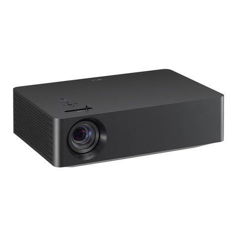
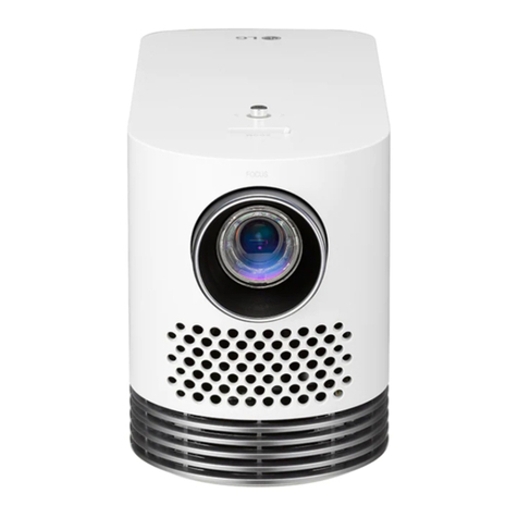
LG HU85LA User manual

CHASSIS :
MODEL :
CAUTION
BEFORE SERVICING THE CHASSIS, READ THE SAFETY PRECAUTIONS IN THIS MANUAL.
SERVICE MANUAL
Copyright © 2021 LG Electronics Inc. All rights reserved. Only training and service purposes.
Any reproduction, duplication, distribution (including by way of email, facsimile or other electronic means),
publication, modification, copying or transmission of this Service Manual is STRICTLY PROHIBITED unless you
have obtained the prior written consent of the LG Electronics entity from which you received this Service Manual.
The material covered by this prohibition includes, without limitation, any text, graphics or logos in this Service
Manual.
P/NO : MFL71485905 (2104-REV00)
HU85LA HU85LA-NA
HU85LG HU85LG-GL
HU85LS HU85LS-EU/ JP/ NA
FZ92B/ C/ D
DLP PROJECTOR

- 2 - Copyright © LG Electronics Inc. All rights reserved.
Only training and service purposes.
CONTENTS
CONTENTS .............................................................................................. 2
SAFETY PRECAUTIONS ........................................................................ 3
SPECIFICATION ...................................................................................... 4
SOFTWARE UPDATE .............................................................................. 7
BLOCK DIAGRAM ................................................................................... 8
EXPLODED VIEW .................................................................................... 9
DISASSEMBLY/ ASSEMBLY GUIDE .................................................... 10
TROUBLE SHOOTING GUIDE ...............................................................23

- 3 - Copyright © LG Electronics Inc. All rights reserved.
Only training and service purposes.
Many electrical and mechanical parts in this chassis have special safety-related characteristics. These parts are identified by in the
Exploded View.
It is essential that these special safety parts should be replaced with the same components as recommended in this manual to prevent
Shock, Fire, or other Hazards.
Do not modify the original design without permission of manufacturer.
General Guidance
An isolation Transformer should always be used during the
servicing of a receiver whose chassis is not isolated from the AC
power line. Use a transformer of adequate power rating as this
protects the technician from accidents resulting in personal injury
from electrical shocks.
It will also protect the receiver and it's components from being
damaged by accidental shorts of the circuitry that may be
inadvertently introduced during the service operation.
If any fuse (or Fusible Resistor) in this PROJECTOR receiver is
blown, replace it with the specified.
When replacing a high wattage resistor (Oxide Metal Film Resistor,
over 1 W), keep the resistor 10 mm away from PCB.
Keep wires away from high voltage or high temperature parts.
Before returning the receiver to the customer,
always perform an AC leakage current check on the exposed
metallic parts of the cabinet, such as antennas, terminals, etc., to
be sure the set is safe to operate without damage of electrical
shock.
Leakage Current Cold Check(Antenna Cold Check)
With the instrument AC plug removed from AC source, connect an
electrical jumper across the two AC plug prongs. Place the AC
switch in the on position, connect one lead of ohm-meter to the AC
plug prongs tied together and touch other ohm-meter lead in turn to
each exposed metallic parts such as antenna terminals, phone
jacks, etc.
If the exposed metallic part has a return path to the chassis, the
measured resistance should be between 1 MΩ and 5.2 MΩ.
When the exposed metal has no return path to the chassis the
reading must be infinite.
An other abnormality exists that must be corrected before the
receiver is returned to the customer.
Leakage Current Hot Check (See below Figure)
Plug the AC cord directly into the AC outlet.
Do not use a line Isolation Transformer during this check.
Connect 1.5 K / 10 watt resistor in parallel with a 0.15 uF capacitor
between a known good earth ground (Water Pipe, Conduit, etc.)
and the exposed metallic parts.
Measure the AC voltage across the resistor using AC voltmeter
with 1000 ohms/volt or more sensitivity.
Reverse plug the AC cord into the AC outlet and repeat AC voltage
measurements for each exposed metallic part. Any voltage
measured must not exceed 0.75 volt RMS which is corresponds to
0.5 mA.
In case any measurement is out of the limits specified, there is
possibility of shock hazard and the set must be checked and
repaired before it is returned to the customer.
Leakage Current Hot Check circuit
IMPORTANT SAFETY NOTICE
1.5 Kohm/10W
0.15µF
To Instrument's
exposed
METALLIC PARTS
Good Earth Ground
such as WATER PIPE,
CONDUIT etc.
AC Volt-meter
When 25A is impressed between Earth and 2nd Ground
for 1 second, Resistance must be less than 0.1
*Base on Adjustment standard
SAFETY PRECAUTIONS

- 4 - Copyright © LG Electronics Inc. All rights reserved.
Only training and service purposes.
SPECIFICATION
NOTE : Specifications and others are subject to change without notice for improvement
.
1. Application range
This spec sheet is applied all of the DLP Projector with
FZ92B/ C/ D chassis.
Chassis Model
FZ92B HU85LA-NA
HU85LS-NA
FZ92C HU85LS-EU
HU85LS-JP
FZ92D HU85LG-GL
2. Requirement for Test
Each part is tested as below without special appointment.
(1) Temperature: 25 °C ± 5 °C, CST: 40 °C ± 2 °C
(2) Relative Humidity: 65 % ± 10 %
(3) Power Voltage
: Standard input voltage (100~240V @ 50/60Hz)
* Standard Voltage of each products is marked by models.
(4) Specification and performance of each parts are followed
each drawing and specification by part number in
accordance with BOM.
(5) The receiver must be operated for about 30 minutes prior
to the adjustment
3. Test method
(1) Performance: LGE PROJECTOR test method followed
(2) Required other specification
- Safety : UL, CSA, IEC, CE specification
- EMC : FCC, ICES, IEC, CE specification
- Wireless: WIFI module, Bluetooth module – US
4. Model General Specification
No Item Specication Remark
Min Typ Max Unit
1Video input applicable
system
ATSC /NTSC M/ ATSC 3.0 HU85LA-KR(Korea)
ATSC /NTSC-M/64&256QAM HU85LA-NA/ HU85LS-
NA(US)
2 Available channel
1) VHF : 02~13 (HU85LA-KR/NA)
2) UHF : 14~69 (HU85LA-KR/NA)
3) DTV : 02-69 (HU85LA-KR/NA)
4) CATV : 01~158 (HU85LA-KR)
CATV : 01~135 (HU85LA-NA/ HU85LS-NA)
5) CADTV : 01~158 (HU85LA-KR)
CADTV : 01~135 (HU85LA-NA/ HU85LS-NA)
6) UHDTV: 02~56 (HU85LA-KR)
7) UHD CATV: 01~158 (HU85LA-KR)
HU85LA-KR( Korea)
HU85LA-NA/ HU85LS-
NA(US)
3 Power 436W Set only
4 Input Voltage AC 100 ~ 240(±10%)V, 50/ 60Hz
5 Market
Korea HU85LA-KR
Global HU85LG-GL
US HU85LA-NA/ HU85LS-
NA
EU HU85LS-EU
Japan HU85LS-JP
6 Picture size 4K (3840 x 2160) With 2way Actuator (na-
tive: 1920x1080)
7 Aspect ratio 16:9 Panel Resolution
8Operating Temperature 0 40 Deg
9 Operating Humidity 80 %
10 Storage Temperature -20 60 Deg
11 Storage Humidity 85 %

- 5 - Copyright © LG Electronics Inc. All rights reserved.
Only training and service purposes.
5. External Input Support Format
5.1. 2D MODE
5.1.1. HDMI Input (PC)
No. Resolution H-freq (kHz) V-freq (Hz) Pixel clock
(MHz) Proposed
1 640*350 31.46 70.09 25.17 EGA
2 720*400 31.46 70.08 28.32 DOS
3 640*480 31.46 59.94 25.17 VESA(VGA)
4 800*600 37.87 60.31 40 VESA(SVGA)
5 1024*768 48.36 60.00 65 VESA(XGA)
6 1360*768 47.71 60.01 84.75 VESA(WXGA)
7 1152*864 54.34 60.05 80 VESA
8 1280*1024 63.98 60.02 109.00 SXGA
-Support to HDMI-PC
9 1920*1080 67.5 60 158.40 WUXGA(Reduced Blanking)
10 1920*1080 135 120 297 UDTV 1080P
11 3840*2160 54 24.00 297.00 UDTV 2160P
12 3840*2160 56.25 25.00 297.00 UDTV 2160P
13 3840*2160 67.5 30.00 297.00 UDTV 2160P
14 4096*2160 53.95 23.97 296.70 UDTV 2160P
15 4096*2160 54 24 297 UDTV 2160P

- 6 - Copyright © LG Electronics Inc. All rights reserved.
Only training and service purposes.
5.1.2. HDMI Input (DTV)
No. Resolution H-freq (kHz) V-freq (Hz) Pixel clock
(MHz) Proposed Remarks
1 640*480 31.46 59.94 25.12 SDTV 480P
2 640*480 31.5 60.00 25.12 SDTV 480P
3 720*480 15.73 59.94 13.50 SDTV, DVD 480I(525I)
Spec. out
but display
4 720*480 15.75 60.00 13.51 SDTV, DVD 480I(525I)
5 720*576 15.62 50.00 13.50 SDTV, DVD 576I(625I) 50Hz
6 720*480 31.47 59.94 27 SDTV 480P
7 720*480 31.5 60.00 27.02 SDTV 480P
8 720*576 31.25 50.00 27 SDTV 576P
9 1280*720 44.96 59.94 74.17 HDTV 720P
10 1280*720 45 60.00 74.25 HDTV 720P
11 1280*720 37.5 50.00 74.25 HDTV 720P
12 1920*1080i 28.12 50.00 74.25 HDTV 1080I
13 1920*1080i 33.72 59.94 74.17 HDTV 1080I
14 1920*1080i 33.75 60.00 74.25 HDTV 1080I
15 1920*1080p 26.97 23.97 63.29 HDTV 1080P
16 1920*1080p 27.00 24.00 63.36 HDTV 1080P
17 1920*1080p 33.71 29.97 79.120 HDTV 1080P
18 1920*1080p 33.75 30.00 79.20 HDTV 1080P
19 1920*1080p 56.25 50.00 148.5 HDTV 1080P
20 1920*1080p 67.43 59.94 148.35 HDTV 1080P
21 1920*1080p 67.5 60.00 148.50 HDTV 1080P
22 1920*1080p 112.5 100 297.00 UDTV 1080P
23 1920*1080p 134.86 119.88 296.70 UDTV 1080P
24 1920*1080p 135.00 120 297 UDTV 1080P
25 3840*2160p 53.95 23.98 296.70 UDTV 2160P
26 3840*2160p 54 24.00 297.00 UDTV 2160P
27 3840*2160p 56.25 25.00 297.00 UDTV 2160P
28 3840*2160p 61.43 29.97 296.70 UDTV 2160P
29 3840*2160p 67.5 30.00 297.00 UDTV 2160P
30 3840*2160p 112.5 50.00 594 UDTV 2160P
31 3840*2160p 134.86 59.94 593.40 UDTV 2160P
32 3840*2160p 135 60.00 594 UDTV 2160P
33 4096*2160p 53.95 23.98 296.70 UDTV 2160P
34 4096*2160p 54 24.00 297 UDTV 2160P
35 4096*2160 56.25 25.00 297 UDTV 2160P
36 4096*2160 61.43 29.97 296.70 UDTV 2160P
37 4096*2160 67.5 30.00 297 UDTV 2160P
38 4096*2160 112.5 50.00 594 UDTV 2160P
39 4096*2160 134.86 59.94 593.40 UDTV 2160P
40 4096*2160 135 60.00 594 UDTV 2160P

- 7 - Copyright © LG Electronics Inc. All rights reserved.
Only training and service purposes.
SOFTWARE UPDATE
1. Main Software Download
(1) Download the rmware for that model from the LGE site.
(2) Create an LG_DTV folder at the root of the USB memory.
(3) Copy the downloaded model's rmware to the LG_DTV folder.
(4) Turn on your projector and insert the USB memory.
(5) “Software update” Popup displays after 10 seconds.
(6) Select “Yes” , using right arrow key. Software update will begin. If you don’t want to update SW Select “No”.
(7) If updated successfully, Projector will be turn o automatically.
(8) You can eject USB Memory stick after Projector turned o.
2.Expert Mode
(1) Download the rmware for that model from the LGE site.
(2) Create an LG_DTV folder at the root of the USB memory.
(3) Copy the downloaded model's rmware to the LG_DTV folder.
(4) Turn on your projector and insert the USB memory.
(5) If the software pop-up window appears, close it
(6) Press the [IN START] button on the remote control, in the [System3] menu, change the [USB Expert Mode] to Enable.
(7) Enter the Settings menu and position focus in the General menu.
(8) Press button 7 on adjustment remote control 7 times
(9) Once the SOFTWARE UPDATE UI is created, select Firmware.
(10) Click the Update button.

- 8 - Copyright © LG Electronics Inc. All rights reserved.
Only training and service purposes.
USB2.0
SPK
(5W+5W)
Optical
Engine
IR
Audio AMP
SOC
X-tal
eMMC
WiFi & BT Module
HDMI_3
DMD
Main B/D
USB_0
USB_1
USB_
2
USB2.0 USB_3
HDMI 1
HDMI 2
(ARC)
HDMI_1/2
Tuner
I2S
LAN
SPDIF
Joystick
Optic
EPHY
FPGA
OSC
DDR3
X 4EASerial Flash
OSC
Driver IC
Slave
Flash
Driver IC
Master
Flash
LD Driver
XPR I/F
Block
XPR
Actuator
X-tal
PMD1000
Warping
DDR3
X 4EA
OSC
5W
R/G/B LD
PSU(19V, 15V)
USB-CUSB Type C
Block
Serial Flash
TEMP
Front
X-tal
DLPC B/D
* 435W
8p
24pLD Driver
12V
FAN : 5EA
1. Block Diagram
BLOCK DIAGRAM

Copyright © LG Electronics Inc. All rights reserved.
Only training and service purposes.
EXPLODED VIEW
Many electrical and mechanical parts in this chassis have special safety-related characteristics. These
parts are identified by in the EXPLODED VIEW.
It is essential that these special safety parts should be replaced with the same components as
recommended in this manual to prevent Shock, Fire, or other Hazards.
Do not modify the original design without permission of manufacturer.
IMPORTANT SAFETY NOTICE
AR2
300
310
540
120
600
660
530
Main Board
511
510
512
551
553
550
552
100
Fan
541
410
531
590
560
580
400
Bottom case
Wifi
IR
Temp
700
520 Joy stick
Tact switch
121

- 10 - Copyright © LG Electronics Inc. All rights reserved.
Only training and service purposes.
DISASSEMBLY GUIDE
1. Loosen a screw at Bottom case + top case (12ea)
2. Hold part with hand and turn it over.
3. Lift up Top case
4. loosen a screw on LD shield assy(5EA)
5. Lift up LD shield assy
6. Loosen a screw on Engine screw(5EA)
7. Hold part with hand and lift up Engine
8. Loosen a screw(4EA) and lift up Sub shield assy
9. Loosen a screw(4EA) and lift up Main shield assy
& rear case
6FUHZ
+RRN
10. Loosen a screw(7EA) and lift up PSU shield
11. Loosen a screw(1EA) and lift up PSU

- 11 - Copyright © LG Electronics Inc. All rights reserved.
Only training and service purposes.
- DMD & DMD PCBA Disassembly Guide
(Assembling in reverse order)
(1) After disassembling the top cover assy, make
the heat-sink visible.
(5) Release the locking part of the blue marked part
with a (-) screwdriver, and then remove the DMD.
(6) DMD disassembly and new DMD replacement
(2) Disassemble 4 Heatsink xed Screws (including
Spring).
(3) Separate DMD Heatsink and leaf spring.
(4) Carefully lift the PCBA in the direction of the
arrow. Make the glass surface of the DMD visible
while being attached to the DMD and the PCB.
DMD cable is connected
* Cable must be removed when
replacing DMD PCBA.
Direction
indication
Lock
Un-
Lock
180˚ rotation

- 12 - Copyright © LG Electronics Inc. All rights reserved.
Only training and service purposes.
(7) Attaching Thermal Pad to DMD Heatsink Block
Be careful not to get
smudge on the front of the
DMD or to get dust inside
the engine.
Existing Thermal Pad remaining on
the Heatsink Block surface should
be removed cleanly.
Attach 4 new thermal pads
-Thermal Pad P/N: 4850V00138M [9x3.5x0.5t] 4 sheets attached
-Attach so that the thermal pads do not overlap and stick together.

- 13 - Copyright © LG Electronics Inc. All rights reserved.
Only training and service purposes.
ASSEMBLY GUIDE
6FUHZ
+RRN
1. Insert PSU and drive a screw(1EA)
2. Insert PSU shield and drive a screw(7EA)
3. Fix Main shield assy & rear case and drive a
screw(4EA)
4. Insert Sub shield assy and drive a screw(4EA)
7. Insert LD shield assy and drive a screw(5EA)
8. Assembly Top case
9. Hold part with hand and turn it over.
10. Drive a screw at Bottom case + top case (12ea)
5. Insert Engine holding part with hand
6. Drive a screw(5EA)

- 14 - Copyright © LG Electronics Inc. All rights reserved.
Only training and service purposes.
- Engine structure : Engine Module
◆Engine Assy’s : DMD, Source(LD), Heatsink are assembly by engine company.
- Engine Module P/N
-. AFD74370602 – Digital Optics
-. AFD74370604 – Union Optech
406
323
114.3
UST
lens
Engine fix Boss( 5EA)
DMD Light source
illuminator

- 15 - Copyright © LG Electronics Inc. All rights reserved.
Only training and service purposes.
- Engine structure - Engine Total Assy(Sub assy work)
◆ Engine Sub Assy working
: Engine Module + DLPC Board + DMD FPCB cable
No Parts Name P/N Q’ty Materail Remark
1Engine Module AFD74370602 1-Public
AFD74370604 1
2DMD FPCB CABLE EAX69067501 2 -
3DLPC board Assy EBT66013701 1 -
4Gasket MDS64570159 1 -
5Gasket MDS64242814 2 -
6Screw FAB31843216 4 -
7Caution Label MEZ38075828 1 -
31
2
1) MAIN(DLPC) BD Front
Reference line
4
2) Fixing MAIN(DLPC) BD
on the back of ENGINE
5) connect Actuator cable connector
3) Attach between the GASKET
SILK on the back of FPC CABLE.
55
P100 P101
P900 P600
2 2
Check if the cable guide line is level
with the wafer.
4) DMDMAIN
Cable insert in order
66
66
P1200
5) Attach caution label
7

- 16 - Copyright © LG Electronics Inc. All rights reserved.
Only training and service purposes.
- Set assembly - Sub PCB insertion work guide
◆ Sub PCB(temp, joystick, IR, wifi) changing work
1. Temp sensor, joystick : drive a screw after fix up guide rib and boss
2. IR, wifi : insert in guide rib
*Check the connection status after assembly.
insert in guide rib
5
Check direction CHASSIS
ASSY
1
4
insert in guide rib
Drive a screw after fix up GUIDE
BOSS
Drive a screw after fix up GUIDE
BOSS
5
5
2
3

- 17 - Copyright © LG Electronics Inc. All rights reserved.
Only training and service purposes.
- Set assembly – PSU BD and shield assembly guide
◆ PSU changing work
1. Insert PSU BD and drive a screw.
2. Insert PSU shield and drive a screw. : Check the connection status after assembly.
PSU : Insert to BOTTOM CASE GUIDE BOSS
33
3
4
3
PLATE SHIELD : Insert to same GUIDE BOSS
12
5
3

- 18 - Copyright © LG Electronics Inc. All rights reserved.
Only training and service purposes.
- Set assembly – Main shield and rear case assembly guide
◆ Main shield & rear case changing work
1. After lift up Main shield assy, insert the Rear case. : Be careful not to damage the terminals.
2. Insert Main shield and drive a screw
6
6
5
5
Insert to GUIDE BOSS
MAIN ASSY + CASE REAR assembly
3
Drive a SCREW
No. 5->6
CASE 3P
P104
4
CASE REAR
2
1
Insert to BOSS and drive a
screw

- 19 - Copyright © LG Electronics Inc. All rights reserved.
Only training and service purposes.
- Set assembly –Engine assembly guide
◆ Check the assembly method when replacing engine assy and LD shield assy
1. After installing the engine assy, Fixed it with a screw.
2. after Install LD shield assy, fixed it with screw
2
2
22
1
2
GUIDE BOSS Assembly/Fixed
ENGINE ASSY + CASE assembly
No Part No Description Qty Specification
①AFD74370602 Chassis Assembly 1
KR091276 OPTICAL ENGINE HU85L AFD74370601 SVC BOM Part Only
AFD74370604
UNION OPTICAL ENGINE HU85L Optical Engine HU85LA AFD74370603 SVC BOM Part Only
②FAB30011008 Screw,Taptite 5
FAB30011002 BRH + P 3MM 12mM
③EBT66013801 Chassis Assembly 1
SUB
-(None) HU85LA LD Driver
④FAB31843216 Screw,Machine 4
BRH + 3MM 5.5MM SWCH10A ZN+Ni
⑤FAB3001103 Screw,Taptite 1
FAB30011003 BRH + P 3MM 10MM M
LD DIVER + Engine ASSY Assembly
GUIDE BOSS Assembly/Fixed

- 20 - Copyright © LG Electronics Inc. All rights reserved.
Only training and service purposes.
- Set assembly – Fan Work Guide
◆ Fan changing work
1. Fan : check the arrows on Bottom case (label location/air flow direction)Work to FAN each position.
2. Cushion : It is related with noise. So be careful. (It is located in center of FAN)
FAN MODULE
GASKET
FERRITE CORE
DescriptionPart No
1
2
3
EAL44320708
MDS64155513
6210VH0004B
No
3
<B>
<A>
2
20mmOne turn 50mmOne turn
<C>
2
1
1
2
2
1
2
2
3
Check Fan label direction
(arrows direction is label direction)
<A>
<A>
<A>
<B>
<C>
Other manuals for HU85LA
1
This manual suits for next models
7
Table of contents
Other LG Projector manuals