LG 29FU1RL/RG User manual

COLOR TV
SERVICE MANUAL
CAUTION
BEFORE SERVICING THE CHASSIS,
READ THE SAFETY PRECAUTIONS IN THIS MANUAL.
CHASSIS : CW91A
MODEL : 29FU1RL/RG
MODEL : 29FU1RL/RG-TK
May., 2010
Printed in China
P/NO : MFL62077307
North/ Latin America http://aic.lgservice.com
Europe/Africa http://eic.lgservice.com
Asia/Oceania http://biz.lgservice.com
Internal Use Only
tu2522 tu2522 tu2522 tu2522 tu2522 tu2522 tu2522 tu2522 tu2522 tu2522 tu2522 tu2522 tu2522 tu2522 tu2522 tu2522 tu2522 tu2522 tu2522 tu2522
tu2522 tu2522 tu2522 tu2522 tu2522 tu252

- 2 -
CONTENTS
Contents...................................................................................................................2
Safety Precautions..............................................................................................3
Specifications........................................................................................................4
Adjustment Instructions .................................................................................5
Trouble Shooting.................................................................................................10
Printed circuit board.........................................................................................14
Block Diagram ......................................................................................................16
Exploded View.....................................................................................................18
SVC. Sheet..................................................................................................................
Copyright©2010 LG Electronics.Inc. All right reserved.
Only for training and service purposes.
LGE Internal Use Only
tu2522 tu2522 tu2522 tu2522 tu2522 tu2522 tu2522 tu2522 tu2522 tu2522 tu2522 tu2522 tu2522 tu2522 tu2522 tu2522 tu2522 tu2522 tu2522 tu2522
tu2522 tu2522 tu2522 tu2522 tu2522 tu252

- 3 -
SAFETY PRECAUTIONS
Many electrical and mechanical parts in this chassis have special safety-related characteristics. These parts are identified by in
the Schematic Diagram and Replacement Parts List.
It is essential that these special safety parts should be replaced with the same components as recommended in this manual to
prevent X-RADIATION, Shock, Fire, or other Hazards.
Do not modify the original design without permission of manufacturer.
General Guidance
An isolation Transformer should always be used during
the servicing of a receiver whose chassis is not isolated from
the AC power line. Use a transformer of adequate power rating
as this protects the technician from accidents resulting in
personal injury from electrical shocks.
It will also protect the receiver and it's components from being
damaged by accidental shorts of the circuitry that may be
inadvertently introduced during the service operation.
If any fuse (or Fusible Resistor) in this TV receiver is blown,
replace it with the specified.
When replacing a high wattage resistor (Oxide Metal Film
Resistor, over 1W), keep the resistor 10mm away from PCB.
Keep wires away from high voltage or high temperature parts.
Due to high vacuum and large surface area of picture tube,
extreme care should be used in handling the Picture Tube.
Do not lift the Picture tube by it's Neck.
X-RAY Radiation
Warning:
To determine the presence of high voltage, use an accurate
high impedance HV meter.
Adjust brightness, color, contrast controls to minimum.
Measure the high voltage.
The meter reading should indicate
23.5 ± 1.5KV: 14-19 inch, 26 ± 1.5KV: 19-21 inch,
29.0 ± 1.5KV: 25-29 inch, 30.0 ± 1.5KV: 32 inch
If the meter indication is out of tolerance, immediate service
and correction is required to prevent the possibility of
premature component failure.
Before returning the receiver to the customer,
always perform an AC leakage current check on the exposed
metallic parts of the cabinet, such as antennas, terminals, etc.,
to be sure the set is safe to operate without damage of
electrical shock.
Leakage Current Cold Check(Antenna Cold Check)
With the instrument AC plug removed from AC source,
connect an electrical jumper across the two AC plug prongs.
Place the AC switch in the on position, connect one lead of
ohm-meter to the AC plug prongs tied together and touch other
ohm-meter lead in turn to each exposed metallic parts such as
antenna terminals, phone jacks, etc.
If the exposed metallic part has a return path to the chassis, the
measured resistance should be between 1MΩ and 5.2MΩ.
When the exposed metal has no return path to the chassis the
reading must be infinite.
An other abnormality exists that must be corrected before the
receiver is returned to the customer.
Leakage Current Hot Check (See below Figure)
Plug the AC cord directly into the AC outlet.
Do not use a line Isolation Transformer during this check.
Connect 1.5K/10watt resistor in parallel with a 0.15uF capacitor
between a known good earth ground (Water Pipe, Conduit, etc.)
and the exposed metallic parts.
Measure the AC voltage across the resistor using AC
voltmeter with 1000 ohms/volt or more sensitivity.
Reverse plug the AC cord into the AC outlet and repeat AC
voltage measurements for each exposed metallic part. Any
voltage measured must not exceed 0.75 volt RMS which is
corresponds to 0.5mA.
In case any measurement is out of the limits specified, there is
possibility of shock hazard and the set must be checked and
repaired before it is returned to the customer.
Leakage Current Hot Check circuit
The source of X-RAY RADIATION in this TV receiver is the
High Voltage Section and the Picture Tube.
For continued X-RAY RADIATION protection, the
replacement tube must be the same type tube as specified in
the Replacement Parts List.
1.5 Kohm/10W
To Instrument’s
exposed
METALLIC PARTS
Good Earth Ground
such as WATER PIPE,
CONDUIT etc.
AC Volt-meter
IMPORTANT SAFETY NOTICE
0.15uF
Copyright©2010 LG Electronics.Inc. All right reserved.
Only for training and service purposes.
LGE Internal Use Only
tu2522 tu2522 tu2522 tu2522 tu2522 tu2522 tu2522 tu2522 tu2522 tu2522 tu2522 tu2522 tu2522 tu2522 tu2522 tu2522 tu2522 tu2522 tu2522 tu2522
tu2522 tu2522 tu2522 tu2522 tu2522 tu252

- 4 -
VScope
This specification applies to CTV models based on chassis
CW91A .
VSPECIFIC
Testing should be done at given condition if no condition is specified
1) Ambient Temperature : 25±5°C (CST 40±5°C)
2) Ambient Humidity : 65±10%
3) Input Voltage : Standard input voltage (110~240V ac 50/60Hz)
4) All BOM mentioned component should be same quality standard
as mentioned in specs./ drawing of that particular Part No.
5) Testing should be done after 20 minute heat run.
6) Power Voltage
VTesting and Inspection Method
1) Performance Testing --- According to LG TV Testing Standard
2) Required Regulations
No
1
2
3
4
5
6
7
8
9
10
Item
Receiving System
Available Channel
Input Voltage
Market
Screen Size
Aspect Ratio
Display Method
Tuning System
Operating Environment
Storage Environment
Remark
China / Indonesia/ Thai/ Vietnam
CIS
L.America/ Philippine/Taiwan
Asia/Middle East/Africa
PAL Model
NTSC Model
Asia
Others
PAL Model
NTSC
Specification
PAL BG.DK.I / NTSC M(AV3.58/4.43)
SECAM DK
PAL NM / NTSC M(AV3.58)
PAL BG,DK,I / NTSC M(AV3.58/4.43)
SECAM BG,DK,L
VHF : E2 ~ E12
UHF : E21 ~ E69
CATV : S1 ~ S20
HYPER : S21 ~ S41
VHF : 2~13CH(12CH)
UHF : 14~69CH(56CH)
CATV : 1 ~ 125CH(113CH)
AC 220Vac 50/60Hz
AC 110~240V 50/60Hz
Latin America, China, Indonesia
Philippines, Taiwan, Thai, Vietnam,
Asia/Africa,CIS
29 inch Flat / Super slim
4:3
CRT
FVS
FS
1)Temp : 0 ~ 40 deg
2)Humidity : ~ 85 %
3)Temp : -20 ~ 60 deg
4)Humidity : ~ 90 %
VGeneral Specification
Market Place
Middle East/Africa
Band
LG
Standard input Voltage
AC110 ~240V 50/60Hz
Remarks
SPECIFICATIONS
Note : Specification and others are subject to change without notice for improvement.
Copyright©2010 LG Electronics.Inc. All right reserved.
Only for training and service purposes.
LGE Internal Use Only
Market Place
Middle East/Africa/cis
Compliance
Safety : CB(IEC60065)
EMC : CE(EN55020,EN55013)
Remarks
tu2522 tu2522 tu2522 tu2522 tu2522 tu2522 tu2522 tu2522 tu2522 tu2522 tu2522 tu2522 tu2522 tu2522 tu2522 tu2522 tu2522 tu2522 tu2522 tu2522
tu2522 tu2522 tu2522 tu2522 tu2522 tu252

1. Scope of Application
These adjustment instructions are applicable to CW91A
Chassis whether SET(0), SKD(0), or CKD(0).
2. Notes
2.1 Because this is a cold chassis, it is not necessary to use
an isolation transformer. However,operating it using a
transformer between the power supply line and chassis
input to prevent electric shock and to protect the test
instrument.
2.2 All adjustments must be done in correct sequence.
However, for better productivity, it can be changed in a pre-
permitted range.
2.3 Environment conditions: If not specified, it must be done in
following conditions.
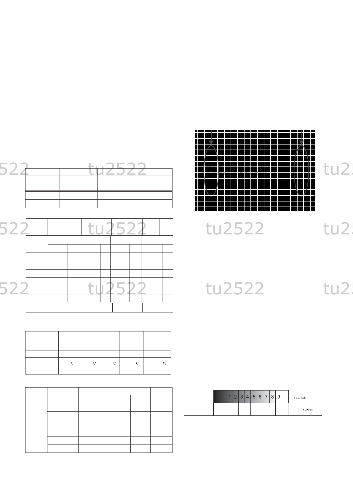
1) Temperature: 25°C ±5°C
2) Humidity : 65%±10%
2.4 Power supply of SET
1) NTSC
Latin America/Philippines Market:100~240V ±10%,50/60Hz
Korea Market : 220V ±10%,60Hz
Taiwan Market : 110V ±10%,60Hz
Japan Market : 100V ±10%,50/60Hz
2) PAL/SECAM
China/Indonesia/Thailand/Vietnam/CIS Market :
100~240V ±10%, 50/60Hz
2.5 If not specified, the receiver must be operated for more
than 20 minutes prior to the adjustment.
2.6 Signal: Received the standard color signal. (65dB±1dBuV)
NTSC: LG standard signal means the digital pattern
13CH(480NC).
PAL/SECAM: LG standard signal means the digital
pattern PAL-B/Gz 05CH
2.7 If not specified, APC ON is APC CLEAR (DYNAMIC).
3. Adjustment content
3.1. Screen Voltage Adjustment
3.1.1.Adjustment (Use factory remote control)
(1) Input in the 75Ωcable LG standard signal
(Digital Pattern,480NC)
(2) Press IN-START KEY and ADJ KEY of SVC T/X
generate horizontal line for Screen adjust.
(3).Turn the screen volume on the FBT clockwise until the
horizontal line is visible and turn it counterclockwise until
horizontal line faintly visible.
(Exit screen voltage adjustment by press “Exit” key of SVC
T/X.)
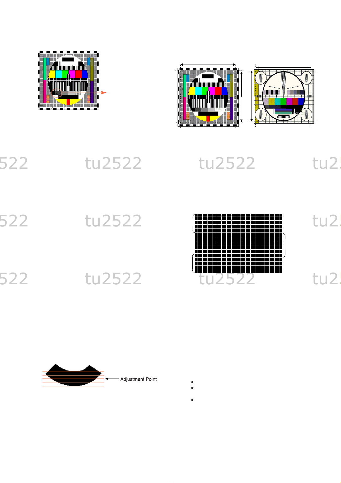
3.2. Purity and Convergence Adjustment
3.2.1. Purity adjustment
(1). Adjustment Preparation
a. Received Red Raster Pattern for purity adjustment (51CH).
b. Demagnetize the CPT and Cabinet with a degaussing coil.
(2). Adjustment
a. Pre-adjust the static convergence(STC) with the 4 and
6-pole magnet.
b. If the horizontal Line is inline with CPT Mark,2-Pole
magnet should direct 3-9 o’clock direction.
c. If not,direct 2-Pole magnet handle toward 6-12 o’clock
direction and adjust the Horizontal Line to fall onto the
mark opening the magnet at an angle.
d.Push the DY(deflection yoke) all the way to the CPT funnel.
e.Turn the purity magnet(2-pole magnet) so that the “green”
color portion of left side and the “blue” color portion on
the right side have equal amount of color.
f.Pull the DY slowly backward and fix it when the whole
screen becomes red.
(The specified torque for fixing DY screw should be 10Kg/cm.)
3.2.2. Convergence adjustment
(1). Necessary Instrument
a. Degaussing Coil
b. Convergence fixing instrument(special tools)
(2). Adjustment Preparation
a. Operate the unit at the least 15 minutes before adjustment.
b. Using degaussing coil,remove the stains on CPT & Cabinet.
c. Received the Cross Hatch Pattern for Convergence (09ch).
d. Let the Contrast in normal luminance level.
(3). Static Convergence (STC) Adjustment
a. Received the Cross Hatch Pattern for Convergence (09ch).
b. Before adjusting Static Convergence(STC),adjust the
focus first seeing to it that the WHITE color picture quality
is sharp enough.
c. Converge the RED vertical line and BLUE vertical line in
unity(same line) by changing the angle between the 2
tabs of 4-pole magnet.
d. Converge the RED horizontal and BLUE horizontal line
unity(same line) by turning the 2 tabs of the 4-pole magnet.
At this time,do not change the angle between the 2 tabs.
e. Converge the R,G,B vertical line in unity(same line) by
changing the angle between the 2 tabs of the 6-pole magnet.
f. Converge the R,G,B horizontal line in unity(same line) by
turning the 2 tabs of the 6-pole magnet. At this time, do not
change the angle between the 2 tabs.
(4). Dynamic Convergence (DYC) Adjustment
a. Y-Axis Adjustment :Adjust convergence of Y-axis(vertical)
by moving the deflection yoke(DY) left and right.
b. X-axis Adjustment : Adjust convergence of X-axis(horizontal)
by moving the deflection yoke(DY) up and down.
3.3. White Balance Adjustment
3.3.1. Necessary Instrument
(1). Auto white balance meter (Low/High Light Pattern generator)
(2). CRT Color Analyzer, CA-100 :1 set
(3). Factory Remote control
3.3.2. Adjustment preparation : Prior to this adjustment, the
Screen Voltage adjustment should be finished.
3.3.3. Auto Adjustment
(1). Adjust using Auto White Balance Meter.
(2).Enter CPU OFF mode by press the “IN-START” &”MUTE”
key of factory remote control in turn before adjustment.
Exit CPU OFF mode by press the “MUTE” key of factory
remote control after adjustment finished.
In case there is excess RED color at screen voltage
adjustment, adjust it using “Volume -(F)”Key of factory remote
control until the RED color disappear.
- 5 -
ADJUSTMENT INSTRUCTIONS
Copyright©2010 LG Electronics.Inc. All right reserved.
Only for training and service purposes.
LGE Internal Use Only
GRB GRB
GRB R
tu2522 tu2522 tu2522 tu2522 tu2522 tu2522 tu2522 tu2522 tu2522 tu2522 tu2522 tu2522 tu2522 tu2522 tu2522 tu2522 tu2522 tu2522 tu2522 tu2522
tu2522 tu2522 tu2522 tu2522 tu2522 tu252

3.3.4. Manual Adjustment
(1). Adjust using white balance meter and factory remote control.
(2). Enter white balance adjustment mode by press “IN-START”
key of factory remote control.
(3). Use the CHD, CHEkey to choose adjustment item.
(4). Use the VOLF,VOLGKey to change item data.
(5). Adjustment Procedure
a. Make the picture luminance 45Ft-L by change the
“CONTRAST” and “BRIGHTNESS”.
b. Adjust X data of high light with R DRIVE and Y data of high
light with B DRIVE to have color temperature as shown below.
c. Make the picture luminance 4.5Ft-L by change the
“CONTRAST” and “BRIGHTNESS”.
d. Adjust X data of low light with R BIAS and Y data of low light
with B BIAS to have color temperature as shown below.
e. Repeat steps a~d until both low and high light have same
reading as shown below.
3.3.5. CW91A WHITE BALANCE IIC PARAMETER
(1) W/B auto adjust machine setting Table
(2) White balance IIC Parameter (Address)
(3) Color coordinate
Tolerance Range : Adjust within ±5 for each X,Y coordinate
(4) White Balance default setting data
3.5. Focus Voltage Adjustment
Adjustment must be done after operating the TV set receiver
sufficiently.
3.5.1. Adjustment Preparation
Received the LG standard pattern (PAL :Digital
Pattern,480NC,13CH, NTSC: Crosshatch pattern, Ch.09 )
and set the picture condition on “APC ON” (CLEAR) mode.
3.5.2. Adjustment Turn the focus volume on the FBT upper
direction to have the best focus vertical line and horizontal
line as shown below.
3.6. SUB-BRIGHTNESS Adjustment (Do not adjust)
This adjustment must be done after the White balance
Adjustment
3.6.1. Adjustment preparation
(1).NTSC
-. Received LG standard Mono scope pattern (CH14).
-. Set the picture condition on “APC ON” (CLEAR) mode.
(2). PAL
-. Received PAL B/G 5CH pattern.
-. Set the picture condition on “PSM ON” (DYNAMIC) mode.
3.6.2. Adjustment
(1). Press the “ADJ” key of the factory remote control twice to
enter to “SUB-BRIGHTNESS” adjustment mode.
(2). NTSC MODEL: Change the Sub-Brightness data by
pressing the VOLF,VOLGKEY so that the number 1 in
gray scale of mono scope pattern almost disappear.
In the ultra slim, Do until the number “1” completely
disappear. (See figure 2)
(3). PAL MODEL: Change the Sub-Brightness data by
pressing the VOLF,VOLGKEY so that the 1th, 2th
Black Level in gray scale of PAL B/G 05CH pattern have
a little bit of difference. (See figure 3)
Program
Sub Add
Start Bit
Stop Bit
Offset
Polarity
EPRom_S
(R)_Amp
Win31_wb TWB
20
5
0
0
1
72
(R)_Cut
Win31_wb TWB
17
5
0
0
1
6A
G_Amp
Win31_wb TWB
21
5
0
0
0
68
- 6 -
Program
VCD Slave
Win31_wb
TWB
8A
Eeprom_Slave
Win31_wb TWB
A2
Speed
1
Delay
30
VDC IC
EEPROM
NAME MAKER
NOTE
Algorithm
Speed/Plus 2
22
2
G_Cut
Win31_wb TWB
18
5
0
0
0
6B
ITEM EU N-EU PhilippinesTaiwan Latin
America
288
295
9000
X
Y
Color
Temperature
282
288
10000
267
276
13000
268
273
13000
266
282
13000
Copyright©2010 LG Electronics.Inc. All right reserved.
Only for training and service purposes.
LGE Internal Use Only
LOW
LIGHT
HIGH
LIGHT
ITEM
BLO-R(R CUT)
BLO-G(G CUT)
BLO-B(B CUT)
RG(R DRIVE)
GG(G DRIVE)
BG(B DRIVE)
Default setting data
PAL NTSC
32
32
32
32
32
32
32
32
32
32
32
32
remark
Fixed
Fixed
Range
0~63
0~63
0~63
0~63
0~63
0~63
US 51CH
[Fig 1] Cross-Hatch Pattern(NTSC:US 51CH, PAL:C-8 CH)
[figure 2] MONO SCOPE Pattern signal
tu2522 tu2522 tu2522 tu2522 tu2522 tu2522 tu2522 tu2522 tu2522 tu2522 tu2522 tu2522 tu2522 tu2522 tu2522 tu2522 tu2522 tu2522 tu2522 tu2522
tu2522 tu2522 tu2522 tu2522 tu2522 tu252

3.6.3. Sub-Tint Adjustment (Do not adjust)
This adjustment has to be done only if the picture has bad
tint otherwise, it can be omitted if the picture has good tint.
(1). Received LG standard pattern signal (SMPTE, 2CH).
(2). Set the picture condition on “APC ON” (CLEAR) mode.
(3). Press the “ADJ” key of the factory remote control three
times to enter to “SUB-TINT” adjustment mode.
(4). Change the Sub-Tint data by pressing the VOLF,VOLGKey
until the upper and lower CYAN color becomes same color.
3.7. Deflection Setting Data Adjustment
These adjustment will be done by Auto Adjustment Equipment.
For manual adjustment, it is also possible by the following
procedure.
3.7.1. Adjustment Preparation
(1) Deflection setting data adjustment can be done only with
remote control.
(2) Press the “INSTART” Key on the factory remote control
continuously to enter to Deflection Adjustment mode.
(3) Press the CHD,EKey to select adjustment item.
(4) Press the VOLF,GKey to change the data.
3.7.2. Adjustment
(1) V SLOPE
Half of the picture (bottom part) changed to blank.
Adjust so that half blanked- Picture bottom line in accord
with geometric vertical center of the CPT.
(2) V SHIFT (Vertical Shift)
Adjust so that the horizontal center line of a digital circle pattern
is in accord with geometric horizontal center of the CPT.
(3) V LINEAR (Vertical Linearity)
Adjust so that the boundary line between upper and lower
half is in accord with eometric horizontal center of the CPT
(4) V AMPLIT (Vertical Amplitude)
Adjust so that the circle of a digital circle pattern may be
located within the effective screen of the CPT.
(5) H SHIFT (Horizontal Shift)
Adjust so that the Horizontal center line of a digital circle
pattern is in accord with geometric vertical center of the CPT.
(6) EW WIDTH (Horizontal Width)
Adjust to that a digital circle pattern looks like exact circle.
(7) EW PARAB (East-west PARABOLA)
Adjust so that middle portion of the outer most left and
right vertical line looks like parallel with vertical lines of
the CPT.
(8) EW TRAPE (East-west TRAPEZOID)
Adjust to make the length of top horizontal line same
with it of the bottom horizontal line.
(9) EW UPCOR
Adjust until symmetries upper corner of the screen.
(10) EW LOCOR
Adjust until symmetries upper corner of the screen.
(11) H BOW
Adjust the left and right crooked line on upper and lower side.
(12) H PARALL(ANGLE)
Adjust the vertical slope.
(13) SCORRECT (S-CORRECTION)
Adjust so that all distance between each Vertical lines
are to be the same.
* Pre-settled according to the CPT.
(14) V SCROLL
* Recommend initial setting data
(15) V ZOOM (Vertical Zoom)
* Pre-settled according to the CPT
3.8. Deflection setting Initial data ( SERVICE 2 )
Adjust : It is possible to adjust data.
Recommend : It is recommended, if necessary it is
possible to adjust.
FIX : Don’t change data.
[figure 3] PAL B/G 05CH signal
1th VS 2th
BLACK LEVEL have a
little bit of difference.
(In case of VIETNAM
MODEL 2th VS 3th)
- 7 -
Copyright©2010 LG Electronics.Inc. All right reserved.
Only for training and service purposes.
LGE Internal Use Only
[Figure] PAL Digital Pattern [Figure] NTSC Digital Pattern
(US13CH)
[Figure] Cross-Hatch Pattern (NTSC:US 51CH, PAL:C-8 CH)
UPCOR
LOCOR
EW PARAB
US 51CH
tu2522 tu2522 tu2522 tu2522 tu2522 tu2522 tu2522 tu2522 tu2522 tu2522 tu2522 tu2522 tu2522 tu2522 tu2522 tu2522 tu2522 tu2522 tu2522 tu2522
tu2522 tu2522 tu2522 tu2522 tu2522 tu252

- 8 -
Copyright©2010 LG Electronics.Inc. All right reserved.
Only for training and service purposes.
LGE Internal Use Only
3.10. OPTION Adjustment data Table
3.10.1. Preparation for Adjustment
(1) This decides function in accordance with model.
Press the SVC TX adjustment button (IN-START button) at
SVC mode, then adjust the option at OPTION 1, 2, 3, 4 mode.
(2) Mark the option adjustment data like (0,128,65,96) in BOM.
Mark of BOM
The OPTION 1 data is 90, the OPTION 2 data is 96, the
OPTION 3 data is 4, the OPTION 4 data is 17 in this model.
3.10.2. Adjustment Method
(1) Input data directly by the buttons corresponded with
OPTION 1 ?? (0~255), OPTION 2 ?? (0~255),OPTION 3 ??
(0~255), OPTION 4 ?? (0~255).
(2) Select each OPTION function by the CH UP/DOWN button
and then set up each OPTION by the VOL UP/DOWN button.
3.9.3. Picture Setting SVC DATA3 ( SERVICE 4 )
Flat (LPDK) Slim
ITEM
AGC
RG
GG
BG
BLO-R
BLO-G
BLO-B
CDL
L-DLY
RGB-BRI
SUB-BRI
SCR-BRI
AGC take over
Red Gain
Green Gain
Blue Gain
Black level offset Red
Black level offset Green
Black level offset Blue
Cathode Drive Level
Luminance delay time
OSD/TEXT BRIGHTNESS
OSD/TEXT BRIGHTNESS
OSD/TEXT BRIGHTNESS
21
32
32
32
32
32
32
9
8
15
15
30
21
32
32
32
32
32
32
9
8
15
15
30
Description
CPT
.
PAL NTSC Remarks
ITEM
FMWS
MONO
DSG
AGN
BPB
AVLE
AMLOW
BPB2
FFI
DCXO AVL
FM window size
FM demodulator
Audio in/out gain
FM Sound output gain
Bypass BPF(for mono demodulator)
Enable AVL on EW pin
AM sound output gain
Bypass second BPF
Fast filter IF-PLL
DCXO value
2
1
1
0
0
0
0
1
0
1
FM Prescaler(Stereo L/R)
Description
29"
Slim
29"
FLAT
(AK)
29"
Slim
AK2
Remarks
29"
TS
Slim
ITEM
V SLOPE
V SHIFT
V LINEAR
V AMPLIT
H-SHIFT
EW WIDTH
EW PARAB
EW TRAPE
EW UPCOR
EW LOCOR
H BOW
H PARALL
SCORRECT
V SCROLL
V ZOOM
WBR
WBF
V SYNSLI
Vertical slope
Vertical shift
Vertical linearity
Vertical amplitude
Horizontal shift
EW width
Parabola adj
Trapezoid adj
Upper corner adj
Lower corner adj
Horizontal Bow
Horizontal parallelogram
S correction
Vertical Scroll
Vertical zoom
Timing of Wide Blanking
Vertical slicing level
Description
adj.
adj.
adj.
adj.
adj.
adj.
adj.
adj.
adj.
adj.
adj.
adj.
Recommend
Recommend
Recommend
Recommend
Recommend
Recommend
ITEM
WS
BKS
BSD
DSK
COR
PF
RPO
RPA
PWLDAC
IFOFF
CHSE
ACL
BLOC
TEXT-V
TEXT-H
VGUARD
TFR
GAMMA
OSDHPOS
White stretch
Black stretch
Black stretch depth
Dynamic Skin Control
Coring (Peaking)
Peaking center freq. & delay
Ratio pre & over shoot
Ratio pre & after shoot
Peak white limiting
IF demodulator offset
Chroma sensitivity
Automatic color limiting
Black level offset control
Text V position
Text H position
Vertical guard
Black level shift
OSD Gamma correction
OSD Horizontal Position
Description
1
1
0
1
3
0
3
1
3
45
1
1
5
28
5
1
1
1
3
1
1
0
1
3
0
3
1
3
45
1
1
5
28
5
0
1
1
3
Remarks
Slim Flat
LEVEL PART NO. SPECIFICATION DESCRIPTION JOP EXP.
1. EBT30431523 MAIN, CW91A CHASSIS ASSY (0,128,65,96)
3.9.2. Picture Setting SVC DATA1 ( SERVICE 3 )
3.9. SVC Adjustment data table
3.9.1. Picture Setting SVC DATA1 ( SERVICE 1 )
19
31
23
18
24
28
28
29
43
44
42
26
32
21
25
7
2
0
17
41
43
40
29
48
24
32
46
47
38
26
32
21
25
7
2
0
14
43
37
33
32
17
16
40
33
34
37
38
41
21
25
7
2
0
tu2522 tu2522 tu2522 tu2522 tu2522 tu2522 tu2522 tu2522 tu2522 tu2522 tu2522 tu2522 tu2522 tu2522 tu2522 tu2522 tu2522 tu2522 tu2522 tu2522
tu2522 tu2522 tu2522 tu2522 tu2522 tu252

- 9 -
Copyright©2010 LG Electronics.Inc. All right reserved.
Only for training and service purposes.
LGE Internal Use Only
3.10.3. OPTION1 Function
REMARK
FUNCTION
OPTION
0
1
2
3
0
1
0
1
CW91A
CW91C
RESERVED
RESERVED
29INCH
21INCH
WITHOUT PIP
WITH PIP
CHASSIS
INCH
PIP
CODE
3.10.4. OPTION2 Function
REMARK
FUNCTION
OPTION
0
1
0
1
0
1
0
1
LOW CURVE
HIGH CURVE
WITHOUT DUAL SAVING
WITH DUAL SAVING
FM NORMAL DEMODULATION
FM HIGH DEVIATION DEMO-
WITHOUT A2STEREO
WITH A2STEREO
VOL CURL
DUAL
HIDEV
A2STEREO
CODE
3.10.5. OPTION2 Function
REMARK
FUNCTION
OPTION
0
1
0
1
0
1
0
1
0
1
0
1
0
1
0
1
WITHOUT SCART
WITH SCART
WITHOUT DVD
WITH DVD
WITHOUT SIDE A/V
WITH SIDE A/V
6KEY
4KEY
WITHOUT EYE
WITH EYE
WITHOUTGAME MODULE
WITH GAME MODULE
WITHOUT X-WAVE
WITH X-WAVE
WITHOUT DEGAUSS
WITH DEGAUSS
SCART
DVD
SAV
4KEY
EYE
GAME
XWAVE
DEGAUSS
CODE
3.10.6. OPTION4 Function
REMARK
FUNCTION
OPTION
0
1
2
3
4
5
6
7
0
1
2
3
4
5
6
7
0
1
ENGLISH
NIGERIAN
RESERVED
RESERVED
RESERVED
RESERVED
RESERVED
RESERVED
ENGLISH
EASTASIA
RESERVED
RESERVED
RESERVED
RESERVED
RESERVED
RESERVED
OSD LANG
TXT LANG
TELE TEXT
CODE
3.11. IN STOP Mode setting
Power
Input
LAST CHANNEL
MEMORY
CHANNEL
SOUND
CSM
MUTE
TORBO SOUND
XD
PSM
SSM
BOOSTER
CHILD LOCK
AUTO SLEEP
AVL
BALANCE
EYE
DEGAUSS
1
2
3
4
5
6
7
8
9
10
11
12
13
14
15
16
17
18
ITEM
No. Status
OFF
TV
03CH
VHF: 2~13CH
UHF : 14, 30. 51. 55, 63CH
CATV : 15,16,17, 55, 95CH
30 STEPS
Stamdard
OFF
OFF
ON
Dynamic
FLAT
OFF
OFF
OFF
OFF
0
OFF
OFF
REMARK
OPTION
OPTION
3.12. TV/CABLE TV CHANNEL Operation Condition
1. Necessary parts and instruments
(1) Remote controller (with AIR/CABLE TV button)
2. Checking
(1) Check receiver channel operation for some abnormality
by pressing AIR/CABLE TV button continuously.
tu2522 tu2522 tu2522 tu2522 tu2522 tu2522 tu2522 tu2522 tu2522 tu2522 tu2522 tu2522 tu2522 tu2522 tu2522 tu2522 tu2522 tu2522 tu2522 tu2522
tu2522 tu2522 tu2522 tu2522 tu2522 tu252

TROUBLE SHOOTING
- 10 -
1. RF-STEREO MODEL
1) PICTURE OK / NO SOUND
Check/ Replace TU101 or Input signal
NO
OK
Selected correct system in menu
Check the waveform IF of TU101
Check the voltage at pin 2, 11, 18, 35,
36, 55, 61, 68, 75 of UOC-TOP QFP80
NO
Check/ Replace IC501
NO
Check the voltage at pin 25, 26 of
UOC-TOP QFP80
NO
OK
Check the waveform at pin 64,71of
IC501
OK
Check the waveform at pin 1, 64of
IC601
Check/ Replace Q601
NO
OK
Check the waveform at pin 63 of IC601
Check/ Replace IC601
NO
OK
Check the waveform at pin 2, 72, 76 of
IC601
Check/ Replace R822, D827
Check the Heater voltage of
CPT(6.0~6.4 Vrms)
Check R, G, B out of CPT board
Check IC901,
P403
Check 200V line of CPT Board &
if no problem check and Replace
Check the Heater pulse of FBT T402
Check FR901, P403,
P902B, FR401
Check FBT T402
Check HV, Screen voltage of CPT
Check FBT T402
NO
OK
Check the waveform at pin 71, 77 of
IC601
2) No Raster / Sound OK(1/2)
Copyright©2010 LG Electronics.Inc. All right reserved.
Only for training and service purposes.
LGE Internal Use Only
tu2522 tu2522 tu2522 tu2522 tu2522 tu2522 tu2522 tu2522 tu2522 tu2522 tu2522 tu2522 tu2522 tu2522 tu2522 tu2522 tu2522 tu2522 tu2522 tu2522
tu2522 tu2522 tu2522 tu2522 tu2522 tu252

- 11 -
3) No Raster (2/2)
Check the in/out of
regulator(IC823,
IC824, IC827)
Check pin 20 of
IC501(H_Out) Check the voltage of
C832
Check/ Replace Fuse
Is the voltage each
pin voltage of IC501
Check Fuse of AC line
Check/ Replace
IC501
Check T401 & each
pin voltage
Check Q401collect
waveform
Check & Replace
T402
Check the voltage
pin4 of IC810
Check/ Replace
IC810, IC802, Q830
Check Fuse and Diode of secondary
Load of SMPS trans(T801)
Check the B+at D829
cathode
OPEN
Check/ Replace DB801
NO
Check/ Replace Fuse and IC810
NO
OK
NO
Normal Abnormal
Check/ Replace
Q402
Check/ Replace
T401
Check/ Replace
Q401
Check Q402
collector waveform
Check/ Replace IC501
NO
OK
Copyright©2010 LG Electronics.Inc. All right reserved.
Only for training and service purposes.
LGE Internal Use Only
tu2522 tu2522 tu2522 tu2522 tu2522 tu2522 tu2522 tu2522 tu2522 tu2522 tu2522 tu2522 tu2522 tu2522 tu2522 tu2522 tu2522 tu2522 tu2522 tu2522
tu2522 tu2522 tu2522 tu2522 tu2522 tu252

- 12 -
4) No Picture/ No Sound
Is any OSD displayed?
OK
NO
NO
OK
OK
NO NO
OK
OK
NO
OK
OK
OK
P20A (R, G, B out of
IC501)
P20A (R, G, B out of
IC501)
Replace IC501
Check pin77, 76
SCL, SDA
Check IC12(EEPROM)
& SCL, SDA, Line
Check pin68 Reset
Voltage
Check IC501 pin 8,
7, 6 (R, G, B out)
Check SMPS Trans
Secondary Voltage
Go to No sound/
picture OK
Check the waveform
pin20(H-out)
Check IC501 pin 8,
7, 6 (R, G, B out)
Check receiving system in MENU
& execute Auto - Program
Does the auto - Program
operate properly
Store on manual -program MENU
Copyright©2010 LG Electronics.Inc. All right reserved.
Only for training and service purposes.
LGE Internal Use Only
tu2522 tu2522 tu2522 tu2522 tu2522 tu2522 tu2522 tu2522 tu2522 tu2522 tu2522 tu2522 tu2522 tu2522 tu2522 tu2522 tu2522 tu2522 tu2522 tu2522
tu2522 tu2522 tu2522 tu2522 tu2522 tu252

- 13 -
2. AV STEREO/ MONO MODEL
Select correct system in menu
OK
OK
OK OK
NO
NO
Does the auto - Program
operate properly Check TU101 Tuner
Check the voltage of pin2, 11,
18, 35, 36,55,61, 68, 75 of IC501
Check the waveform at
pin26, 25 of IC501
OK
Check the signal line of SPK-N,P
Check the waveform at
pin4, 12, of IC601
NO
NO
OK
Check pin71 (mute) of IC501
Check the waveform at
pin6 of IC601
OK
NO
NO
Check the connection of AV
equipment
AV
OK
OK
Check the connection of side
AV Board P201A
Check the voltage at
pin5, 7 of IC601
Check/ Replace
R822, D827
Correct the Board
Check the waveform at
pin8, 9, 11, 12 of IC601
Replace IC601
Copyright©2010 LG Electronics.Inc. All right reserved.
Only for training and service purposes.
LGE Internal Use Only
tu2522 tu2522 tu2522 tu2522 tu2522 tu2522 tu2522 tu2522 tu2522 tu2522 tu2522 tu2522 tu2522 tu2522 tu2522 tu2522 tu2522 tu2522 tu2522 tu2522
tu2522 tu2522 tu2522 tu2522 tu2522 tu252

- 14 -
PRINTED CIRCUIT BOARD
MAIN
Copyright©2010 LG Electronics.Inc. All right reserved.
Only for training and service purposes.
LGE Internal Use Only
tu2522 tu2522 tu2522 tu2522 tu2522 tu2522 tu2522 tu2522 tu2522 tu2522 tu2522 tu2522 tu2522 tu2522 tu2522 tu2522 tu2522 tu2522 tu2522 tu2522
tu2522 tu2522 tu2522 tu2522 tu2522 tu252

- 15 -
CONTROL
LED
Power
Copyright©2010 LG Electronics.Inc. All right reserved.
Only for training and service purposes.
LGE Internal Use Only
tu2522 tu2522 tu2522 tu2522 tu2522 tu2522 tu2522 tu2522 tu2522 tu2522 tu2522 tu2522 tu2522 tu2522 tu2522 tu2522 tu2522 tu2522 tu2522 tu2522
tu2522 tu2522 tu2522 tu2522 tu2522 tu252

BLOCK DIAGRAM
- 16 -
SOUND AMP
LA42102N
(
((
(
FBT
200V
28V
ABL
HEATER
B+ Collector
14V
B+
(115V)
SMPS
TRANS
EER4942
40V
AC
INPUT
(100~240V)
15
11
2
10
9
8
5
4
-14V
1
IC824
ST-6V REG
16
Rear_AV(1)
( PHONE/ SCART)
Rear_AV(1)
( PHONE/ SCART)
IC12
EEPROM
24C16
SIF
SIF
3
14V
Rear_AV(2)
( PHONE/SCART/DVD)
Rear_AV(2)
( PHONE/SCART/DVD)
MenuOKVOL-VOL+PR-PR+
SDA
SCL
5V
33V
12
13
VER. AMP
LA78141
IF VIF
VIF
Saw Filter
3
H OUT TR
2SC6090
Tuner
STR-
W6556
STR-
W6556
RGB Amp
TDA6107AJF
RGB Amp
TDA6107AJF
Sound Vcc
6.5V
IC823
3.3V REG
IC826
5V REG
V Heater
HV
Vscreen
202KJ102KJ
RK,GK,BK
24.576Mhz
21V
5V
R,G,Bout
IK
SIF IN
VIF IN
42
41
46
45 20
21
H-FB
HOUT
49
EW
34
RF/MNT Vout
31 32 33
AV1 V,L,R
28 29 30
AV2 V,L,R
23 24
RF/MNT L,Rout
12 13 14 15
R,G,B FB
Or Y,PB,PR
SPK L,Rout
48
47
VB
VA
6789
R,G,B,IK
60 X-TALIN
59 X-TALOUT
63
ABN
65
DEG
66
EYE
1
IR
76
77
SDA
SCL
2
10
ABL
5
75
3.3V
56
DECDIG(2.5V)
55
35
18
5V
36
8V
1
68
1.8V
67
KEY
25 26
64 PWR
71
S-MUTE
72 SAW S/W
6
57
2
4
SPK R
SPK L
S-MUTE
1.8V(RF ST)
2.5V
8V(AV ST Opt)
5V
ST-3.3V
EW IC
KIA4558
HV &
H Comp
Circuit
HV
TO DY
ST- 3.3V
ST- 5V
220V
RF ST OPT
H DRIVE
TRANS
38V
31V
RF ST OPT
Comp In
Scart in
Copyright©2010 LG Electronics.Inc. All right reserved.
Only for training and service purposes.
LGE Internal Use Only
tu2522 tu2522 tu2522 tu2522 tu2522 tu2522 tu2522 tu2522 tu2522 tu2522 tu2522 tu2522 tu2522 tu2522 tu2522 tu2522 tu2522 tu2522 tu2522 tu2522
tu2522 tu2522 tu2522 tu2522 tu2522 tu252

MEMO
- 17 -
Copyright©2010 LG Electronics.Inc. All right reserved.
Only for training and service purposes.
LGE Internal Use Only
tu2522 tu2522 tu2522 tu2522 tu2522 tu2522 tu2522 tu2522 tu2522 tu2522 tu2522 tu2522 tu2522 tu2522 tu2522 tu2522 tu2522 tu2522 tu2522 tu2522
tu2522 tu2522 tu2522 tu2522 tu2522 tu252

- 18 -
EXPLODED VIEW
300
120
310
530
600
540
504
331
330 320
590
112
913
170 150
943
400
105
503
520
174
501
580
option 570
option
Many electrical and mechanical parts in this chassis have special safety-related characteristics.These
parts are identified by in the Schematic Diagram and EXPLODED VIEW.
It is essential that these special safety parts should be replaced with the same components as
recommended in this manual to prevent X-RADIATION,Shock, Fire, or other Hazards.
Do not modify the original design without permission of manufacturer.
IMPORTANT SAFETY NOTICE
Copyright©2010 LG Electronics.Inc. All right reserved.
Only for training and service purposes.
LGE Internal Use Only
tu2522 tu2522 tu2522 tu2522 tu2522 tu2522 tu2522 tu2522 tu2522 tu2522 tu2522 tu2522 tu2522 tu2522 tu2522 tu2522 tu2522 tu2522 tu2522 tu2522
tu2522 tu2522 tu2522 tu2522 tu2522 tu252

P/N:3854VA0196H
tu2522 tu2522 tu2522 tu2522 tu2522 tu2522 tu2522 tu2522 tu2522 tu2522 tu2522 tu2522 tu2522 tu2522 tu2522 tu2522 tu2522 tu2522 tu2522 tu2522
tu2522 tu2522 tu2522 tu2522 tu2522 tu252

SVC. SHEET : 3854VA0196H-S
tu2522 tu2522 tu2522 tu2522 tu2522 tu2522 tu2522 tu2522 tu2522 tu2522 tu2522 tu2522 tu2522 tu2522 tu2522 tu2522 tu2522 tu2522 tu2522 tu2522
tu2522 tu2522 tu2522 tu2522 tu2522 tu252
This manual suits for next models
1
Table of contents
Other LG TV manuals