- 4 -
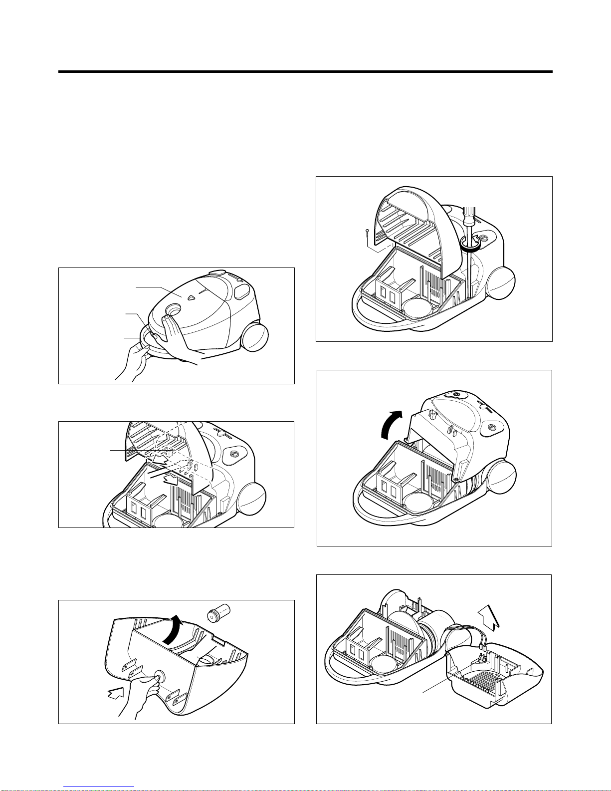
1. Motor exchange
1) Separate the Body Cover and Body Base by
unfastening the screws.
2) Disconnect the lead wires.
3) Lift the old motor and replace it with a new one.
2. In case of exchanging other parts, refer to the
exploded view.
1. Strong Suction Power
This vacuum cleaner has a strong suction power because
it utilizes a highly efficient and powerful motor.
2. Automatic Cord Winding Mechanism
It is very convenient becasue it winds the cord
automatically after operating the unit.
3. Vacuum Power Adjustment
It is very convenient becasue vacuum power varies with
cleaning work by moving the slide knob.
4. Convenient Push Button Switch
Using the switch located in the main body, this vacuum
cleaner can be operated easily.
5. Excellent Running
Running is execllent by adopting large wheel.(ф190)
8. Miscellaneous
1) The dust indicator shows you red color when to
exchange the filter bag or to clean the cloth bag.
2) The washable cloth bag can be used for a long time.
SERVICING PRECAUTIONS
SPECIFICATIONS
FEATURES
BEFORE ATTEMPTING TO SERVICE OR ADJUST ANY PART OF THE VACUUM CLEANER, DISCONNECT THE
ELECTRICAL POWER SUPPLY CORD FROM THE WALL OUTLET.
THIS VACUUM CLEANER IS THE MOST MODERN STYLE GOODS, SUITABLE FOR HOUSEHOLD USE AND IT
RUNS AFTER A NEW VARIATION IN ORDER TO MEET MODERN LIFE SENSE BY IMPROVING THE DESIGN,
THE STRUCTURE AND THE POWER.
• MODEL : V-3310/D/L/T, V-3300/D/L/T/DV
• POWER SOURCE : ON RATING PLATE
• POWER CONSUMPTION : ON RATING PLATE
• POWER CONTROL :
-MAIN : SLIDE CONTROL
(V-3300/D/L/T/DV, V-3314/D/T, TURBO 3300/R)
PUSH ON/OFF
(V-3310/D/L/T, V-3340/D/T, TURBO 3100/B)
-SUB : VACUUM POWER ADJUSTMENT BY
SLIDE KNOB
• CAPACITY : 3.3 L
• CORD LENGTH : 5 m
• HOSE LENGTH : 1.5 m
• NET WEIGHT : 4 kg
• PACKING WEIGHT : 6.2 kg
• NET DIMENSION : 284×433×231 (W×D×H)mm
• PACKING DIMENSION :
331×517×350 (with plastic,
steel, and aluminium pipe)
331×582×350 (with telescopic
pipe)(W×D×H)mm
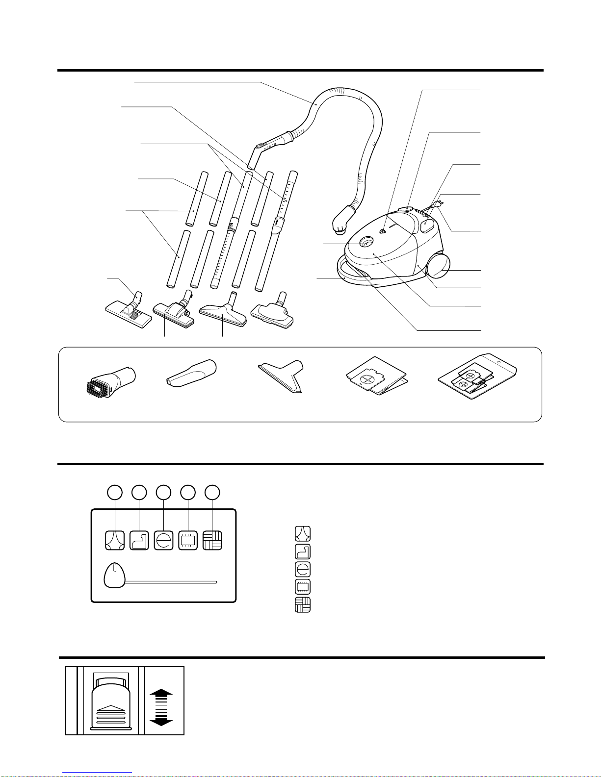
• ATTACHMENTS
HOSE ......................................................................... 1EA
ALUMINIUM PIPE ASM ..............................................2EA
(V-3310L/3300L, TURBO 3300)
STEEL PIPE ASM...................................................... 2EA
(V-3300D/3310D/3314D/3340D/3300DV, TURBO3300,
V-C3043ND)
TELESCOPIC PIPE ASM........................................... 1EA
(V-3300T/3310T/3314T/3340T, V-C3345ST)
PLASTIC PIPE ........................................................... 2EA
(V-3300/3310/3314/3340, TURBO3100/B, V-C3333SB)
NOZZLE ASM..............................................................1EA
CREVICE TOOL......................................................... 1EA
CLOTH BAG ASM(OPTION).......................................1EA
EXTRA PAPER BAG ASM(PAPER, OPTION)............1EA
DUSTING BRUSH(OPTION)...................................... 1EA
UPHOLSTERY NOZZLE(OPTION)............................ 1EA
• This specifications are subject to change according to the buyer's request.