-3-
SAFETY PRECAUTIONS
BEFORE OPERATING THIS VACUUM CLEANER, READ THIS SERVICE MANUAL THOROUGHLY,
AND OBSERVE EACH POINT CAREFULLY.
1. Change the pape bag o clean the cloth
bag in case the indicato moves towa d ed.
) If the dust bag is full, intake power will be reduced.
2) When the dust bag is full of dust, pull out the dust
bag from the inside of body base.
2. Filte
) The filter is composed of a clean filter, an exhaust fil-
ter and a paper bag or a cloth bag.
2) Never use the vacuum cleaner without filters.
It may harm to the motor.
3) When the cloth bag, the clean filter and the exhaust
filter are soiled, wash the filter with neutral cleanser.
Note : Re-use of the cloth bag, clean filter and exhaust
filter.
• Never wash the filter in a washing machine or in a
dishwasher.
• Never use hot water for washing the filter.
• Re-use the filter after drying it completely in the shade.
• Do not dry near fire or direct sun ray.
3. Dust indicato
Dust indicator shows you red color when the filter is full
of dust.
Then, change the paper bag with new one or clean the
cloth bag.
4. Avoid suction such mate ials as:
) Liquid or wet dust:
Clogging the ventilation holes, reduces the intake
power significantly and harms the motor.
2) Inflammable liquids such as benzene, alcohol or sol-
vents.
3) Burning objects such as cigarette butts.
4) Bulky objects such as vinyl, paper etc.
5) Sharp objects such as needles, pins, metal or glass
particles etc.
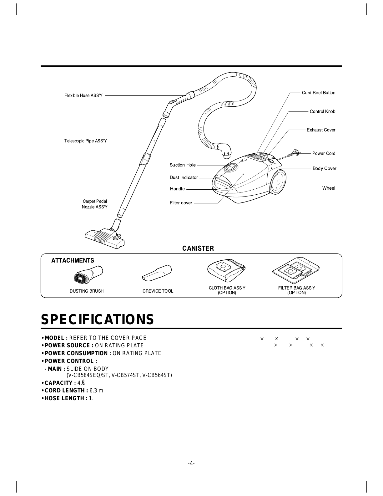
5. Attachments
• Nozzle : For cleaning wooden floor, the room floor and
carpet.
• Crevice Tool: for cleaning any crevice, inside corners
of window frames.
However, do not use the crevice tool more than 20 min-
utes because it may cause harm to the motor.
6. Close supe vision is necessa y when this
vacuum cleane is used by o nea child en.
Child en's ca elessness may cause damage
to the cleane o inju e pe sons.
7. Ai exhausted f om the vacuum cleane is
no mally wa m. But if ext ao dina ily hot ai
is exhausted, check if the telescopic tube,
hose o dust bag is clogged o not.
8. Elect ic shock could occu if used outdoo s
o on wet su faces.