Libelium Waspmote User manual

4-20 mA Current Loop
Sensor Board

-2-
v7.1
Index
Document version: v7.1 - 02/2017
© Libelium Comunicaciones Distribuidas S.L.
INDEX
1. General ................................................................................................................................................ 4
1.1. General and safety information..............................................................................................................................................4
1.2. Conditions of use .........................................................................................................................................................................4
2. Waspmote Plug & Sense!..................................................................................................................... 5
2.1. Features ...........................................................................................................................................................................................5
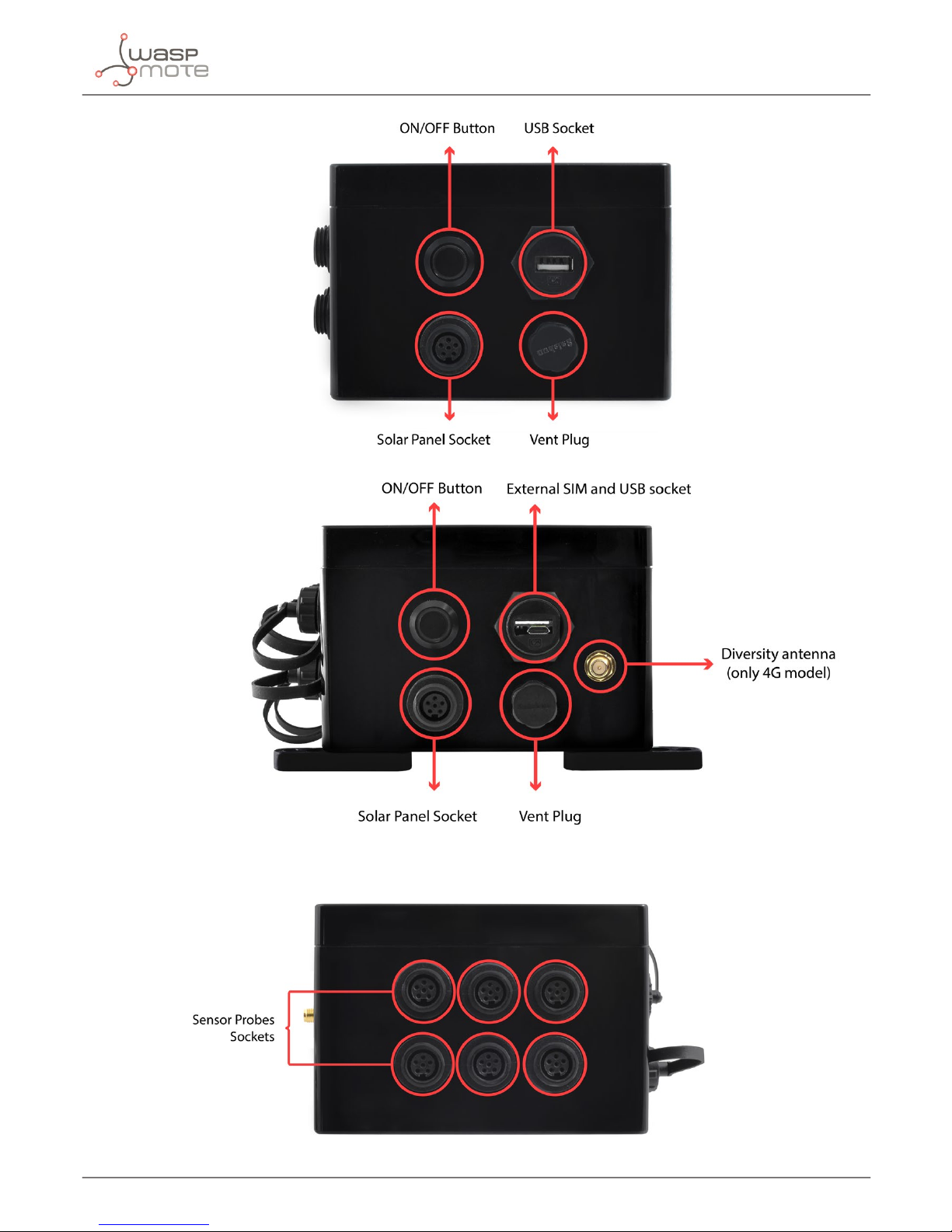
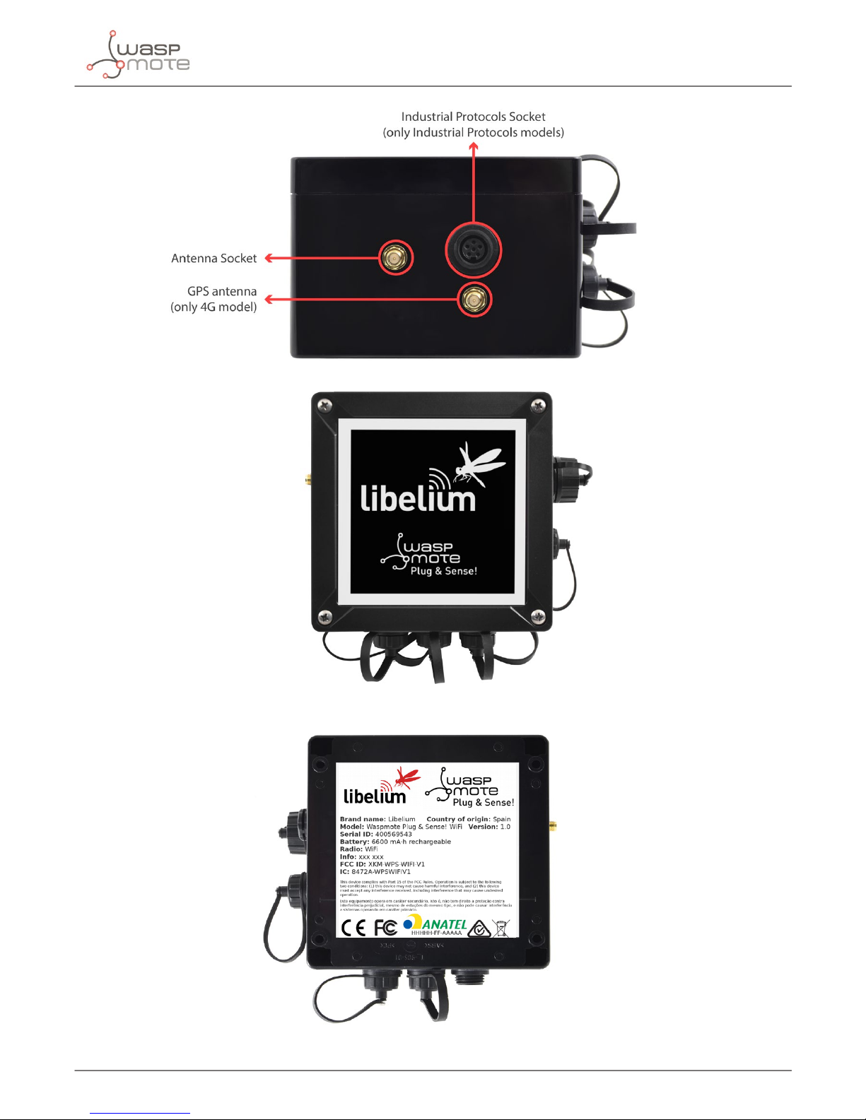
3. General view ........................................................................................................................................ 6
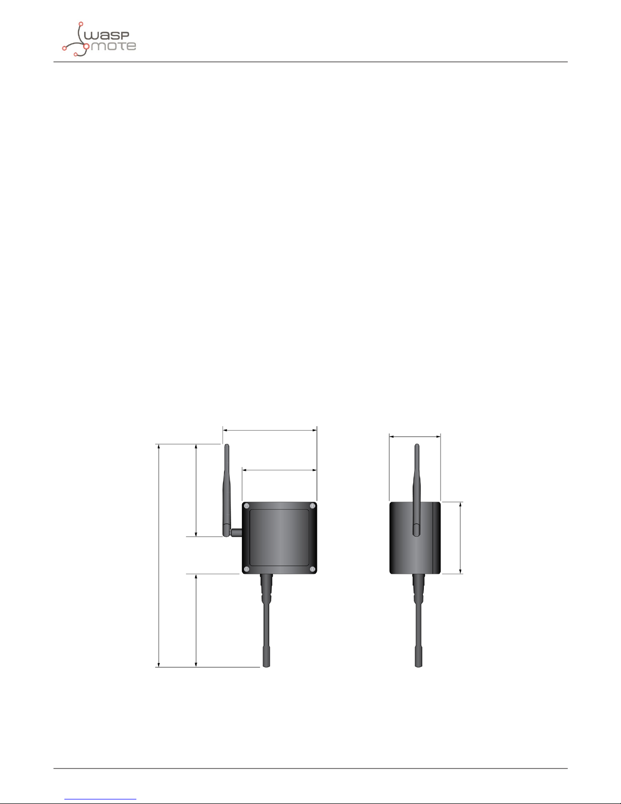
3.1. Specications ................................................................................................................................................................................6
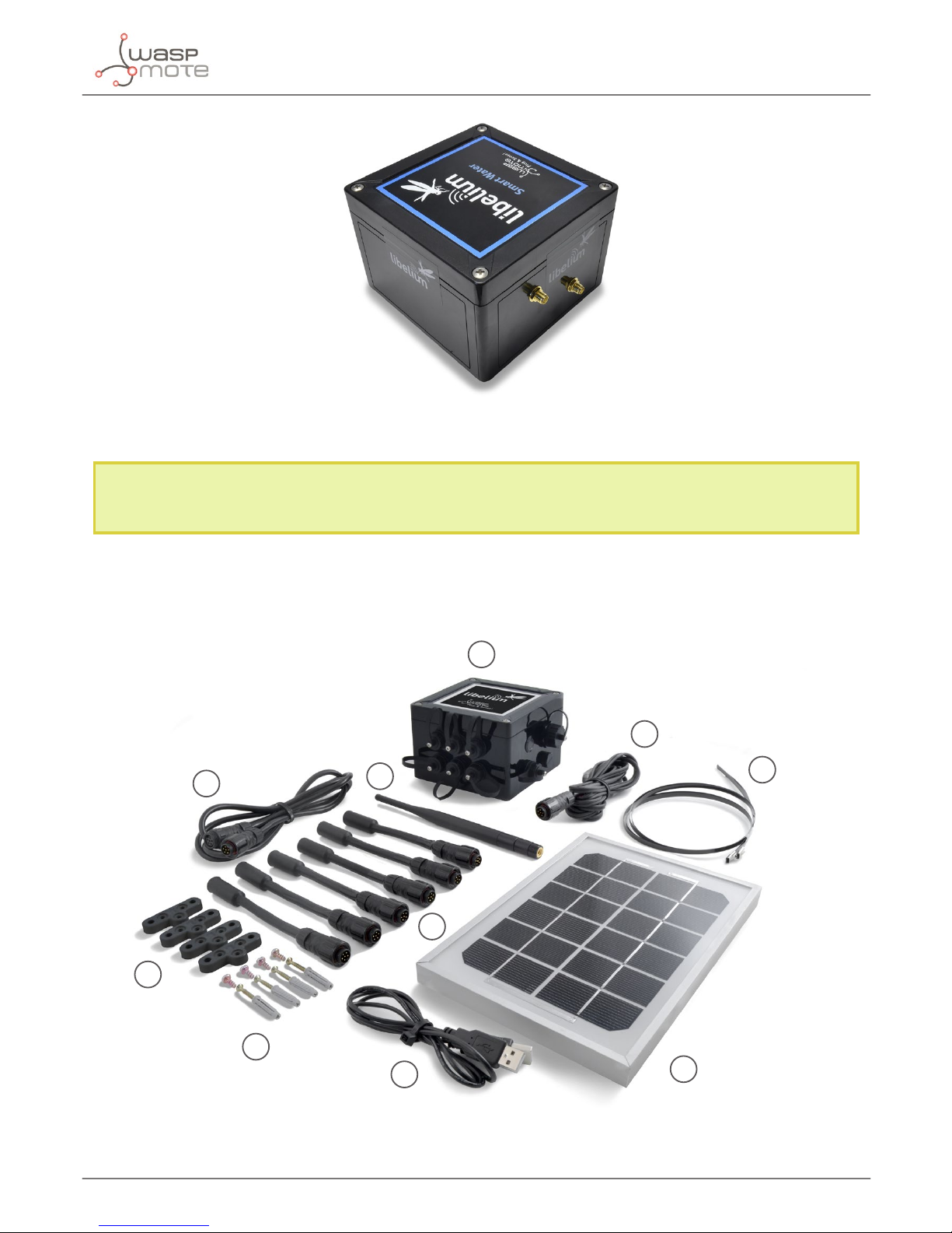
3.2. Parts included................................................................................................................................................................................9
3.3. Identication...............................................................................................................................................................................10
4. Sensor probes .................................................................................................................................... 12
5. Solar powered.................................................................................................................................... 12
6. Programming the Nodes................................................................................................................... 14
7. Radio interfaces................................................................................................................................. 16
8. Industrial Protocols ........................................................................................................................... 17
9. Introduction....................................................................................................................................... 20
9.1. The standard ...............................................................................................................................................................................20
9.2. Power Supply..............................................................................................................................................................................20
9.3. Transmitters categories...........................................................................................................................................................21
9.3.1. Type 2 loop current....................................................................................................................................................21
9.3.2. Type 3 loop current....................................................................................................................................................21
9.3.3. Type 4 loop current....................................................................................................................................................22
10. Hardware.......................................................................................................................................... 23
10.1. Electrical characteristics....................................................................................................................................................... 23
10.2. Connection diagram..............................................................................................................................................................24
10.3. Channel wiring for Plug & Sense!......................................................................................................................................25
10.4. Sensor connection on Plug & Sense! ..............................................................................................................................26
10.4.1. Terminal box probe.................................................................................................................................................26
10.4.2. DB9 probe...................................................................................................................................................................27
10.5. Consumption ...........................................................................................................................................................................27
10.6. Connectors................................................................................................................................................................................ 28
10.7. Powering sensors from the 4-20 mA Board ..................................................................................................................28

-3-
v7.1
11. Applications..................................................................................................................................... 29
12. Libelium library ............................................................................................................................... 30
13. Library functions ............................................................................................................................. 31
13.1. Library constructor ................................................................................................................................................................31
13.2. Switching the board on........................................................................................................................................................31
13.3. Switching the board o........................................................................................................................................................31
13.4. Reading data ............................................................................................................................................................................32
13.5. Current loop state...................................................................................................................................................................32
14. Real application example ............................................................................................................... 33
15. Code examples and extended information................................................................................... 35
16. API changelog.................................................................................................................................. 37
17. Documentation changelog............................................................................................................. 38
18. Certications.................................................................................................................................... 39
Index

-4-
v7.1
General
1. General
1.1. General and safety information
• In this section, the term “Waspmote”encompasses both the Waspmote device itself and its modules and sensor boards.
• Read through the document “General Conditions of Libelium Sale and Use”.
• Do not allow contact of metallic objects with the electronic part to avoid injuries and burns.
• NEVER submerge the device in any liquid.
• Keep the device in a dry place and away from any liquid which may spill.
• Waspmote consists of highly sensitive electronics which is accessible to the exterior, handle with great care and avoid
bangs or hard brushing against surfaces.
• Check the product specications section for the maximum allowed power voltage and amperage range and consequently
always use a current transformer and a battery which works within that range. Libelium is only responsible for the correct
operation of the device with the batteries, power supplies and chargers which it supplies.
• Keep the device within the specied range of temperatures in the specications section.
• Do not connect or power the device with damaged cables or batteries.
• Place the device in a place only acºcessible to maintenance personnel (a restricted area).
• Keep children away from the device in all circumstances.
• If there is an electrical failure, disconnect the main switch immediately and disconnect that battery or any other power
supply that is being used.
• If using a car lighter as a power supply, be sure to respect the voltage and current data specied in the “Power Supplies”
section.
• If using a battery in combination or not with a solar panel as a power supply, be sure to use the voltage and current data
specied in the “Power supplies” section.
• If a software or hardware failure occurs, consult the Libelium Web Development section.
• Check that the frequency and power of the communication radio modules together with the integrated antennas are
allowed in the area where you want to use the device.
• Waspmote is a device to be integrated in a casing so that it is protected from environmental conditions such as light, dust,
humidity or sudden changes in temperature. The board supplied “as is” is not recommended for a nal installation as the
electronic components are open to the air and may be damaged.
1.2. Conditions of use
• Read the “General and Safety Information” section carefully and keep the manual for future consultation.
• Use Waspmote in accordance with the electrical specications and the environment described in the “Electrical Data”
section of this manual.
• Waspmote and its components and modules are supplied as electronic boards to be integrated within a nal product. This
product must contain an enclosure to protect it from dust, humidity and other environmental interactions. In the event of
outside use, this enclosure must be rated at least IP-65.
• Do not place Waspmote in contact with metallic surfaces; they could cause short-circuits which will permanently damage it.
Further information you may need can be found at: http://www.libelium.com/development/waspmote
The “General Conditions of Libelium Sale and Use” document can be found at:
http://www.libelium.com/development/waspmote/technical_service

-5-
v7.1
Waspmote Plug & Sense!
2. Waspmote Plug & Sense!
The Waspmote Plug & Sense! line allows you to easily deploy Internet of Things networks in an easy and scalable way, ensuring
minimum maintenance costs. The platform consists of a robust waterproof enclosure with specic external sockets to connect
the sensors, the solar panel, the antenna and even the USB cable in order to reprogram the node. It has been specially designed
to be scalable, easy to deploy and maintain.
Note: For a complete reference guide download the “Waspmote Plug & Sense! Technical Guide” in the Development section of
the Libelium website.
2.1. Features
• Robust waterproof IP65 enclosure
• Add or change a sensor probe in seconds
• Solar powered with internal and external panel options
• Radios available: 802.15.4, 868 MHz, 900 MHz, WiFi, 4G, Sigfox and LoRaWAN
• Over the air programming (OTAP) of multiple nodes at once (via WiFi or 4G radios)
• Special holders and brackets ready for installation in street lights and building fronts
• Graphical and intuitive programming interface Code Generator (coming in 2017)
• Built-in, 3-axes accelerometer
• External, contactless reset with magnet
• External SIM connector for the 4G models
• Fully certied: CE (Europe), FCC (USA), IC (Canada), ANATEL (Brazil), RCM (Australia), PTCRB (USA, cellular connectivity),
AT&T (USA, cellular connectivity)
Figure: Waspmote Plug & Sense!

-6-
v7.1
General view
3. General view
This section shows main parts of Waspmote Plug & Sense! and a brief description of each one. In later sections all parts will be
described deeply.
3.1. Specications
• Material: polycarbonate
• Sealing: polyurethane
• Cover screws: stainless steel
• Ingress protection: IP65
• Impact resistance: IK08
• Rated insulation voltage AC: 690 V
• Rated insulation voltage DC: 1000 V
• Heavy metals-free: Yes
• Weatherproof: true - nach UL 746 C
• Ambient temperature (min.): -10 °C
• Ambient temperature (max.): 50 °C
• Approximated weight: 800 g
In the pictures included below it is shown a general view of Waspmote Plug & Sense! main parts. Some elements are dedicated
to node control, others are designated to sensor connection and other parts are just identication elements. All of them will be
described along this guide.
164 mm
124 mm
175 mm
410 mm
160 mm
122 mm
85 mm
Figure : Main view of Waspmote Plug & Sense!

-7-
v7.1
General view
Figure : Control side of the enclosure
Figure : Control side of the enclosure for 4G model
Figure : Sensor side of the enclosure

-8-
v7.1
General view
Figure : Antenna side of the enclosure
Figure : Front view of the enclosure
Figure : Back view of the enclosure

-9-
v7.1
General view
Figure : Warranty stickers of the enclosure
Important note: Do not handle black stickers seals of the enclosure (Warranty stickers). Their integrity is the proof that Waspmote
Plug & Sense! has not been opened. If they have been handled, damaged or broken, the warranty is automatically void.
3.2. Parts included
Next picture shows Waspmote Plug & Sense! and all of its elements. Some of them are optional accessories that may not be
included.
1
2
3
4
5
7
6
8
9
10
Figure : Waspmote Plug & Sense! accessories: 1 enclosure, 2 sensor probes, 3 external solar panel, 4 USB cable, 5 antenna, 6 cable ties, 7 mounting feet
(screwed to the enclosure), 8 extension cord, 9 solar panel cable, 10 wall plugs & screws

-10-
v7.1
General view
3.3. Identication
Each Waspmote model is identied by stickers. Next gure shows front sticker.
Model identication colour
Enclosure model
Figure : Front sticker of the enclosure
There are many congurations of Waspmote Plug & Sense! line, all of them identied by one unique sticker. Next image shows
all possibilities.
Figure : Dierent front stickers

-11-
v7.1
General view
Moreover, Waspmote Plug & Sense! includes a back sticker where it is shown identication numbers, radio MAC addresses, etc.
It is highly recommended to annotate this information and save it for future maintenance. Next gure shows it in detail.
Figure : Back sticker
Sensor probes are identied too by a sticker showing the measured parameter and the sensor manufacturer reference.
CO - TGS2442
Measure parameter Sensor reference
Figure : Sensor probe identication sticker

-12-
v7.1
Sensor probes
4. Sensor probes
Sensor probes can be easily attached by just screwing them into the bottom sockets. This allows you to add new sensing
capabilities to existing networks just in minutes. In the same way, sensor probes may be easily replaced in order to ensure the
lowest maintenance cost of the sensor network.
Figure : Connecting a sensor probe to Waspmote Plug & Sense!
Go to the Plug & Sense! Sensor Guide to know more about our sensor probes.
5. Solar powered
The battery can be recharged using the waterproof USB cable but also the internal or external solar panel options.
The external solar panel is mounted on a 45º holder which ensures the maximum performance of each outdoor installation.
Figure : Waspmote Plug & Sense! powered by an external solar panel

-13-
v7.1
Solar powered
For the internal option, the solar panel is embedded on the front of the enclosure, perfect for use where space is a major
challenge.
Figure : Internal solar panel
Figure : Waspmote Plug & Sense! powered by an internal solar panel

-14-
v7.1
Programming the Nodes
6. Programming the Nodes
Waspmote Plug & Sense! can be reprogrammed in two ways:
The basic programming is done from the USB port. Just connect the USB to the specic external socket and then to the computer
to upload the new rmware.
Figure : Programming a node
Besides, Libelium is developing a graphical and intuitive programming interface, the Code Generator (coming in 2017).
Figure: Code Generator web application

-15-
v7.1
Programming the Nodes
Over the Air Programming (OTAP) is also possible once the node has been installed (via WiFi or 4G radios). With this technique
you can reprogram, wireless, one or more Waspmote sensor nodes at the same time by using a laptop and Meshlium.
Figure : Typical OTAP process

-16-
v7.1
Radio interfaces
7. Radio interfaces
Radio Protocol Frequency bands Transmission power Sensitivity Range* Certication
XBee-PRO 802.15.4 EU 802.15.4 2.4 GHz 10 dBm -100 dBm 750 m CE
XBee-PRO 802.15.4 802.15.4 2.4 GHz 18 dBm -100 dBm 1600 m FCC, IC, ANATEL,
RCM
XBee 868LP RF 868 MHz 14 dBm -106 dBm 8.4 km CE
XBee 900HP US RF 900 MHz 24 dBm -110 dBm 15.5 km FCC, IC
XBee 900HP BR RF 900 MHz 24 dBm -110 dBm 15.5 km ANATEL
XBee 900HP AU RF 900 MHz 24 dBm -110 dBm 15.5 km RCM
WiFi
WiFi
(HTTP(S), FTP,
TCP, UDP)
2.4 GHz 17 dBm -94 dBm 500 m CE, FCC, IC,
ANATEL, RCM
4G EU/BR
4G/3G/2G
(HTTP, FTP,
TCP, UDP)
GPS
800, 850, 900, 1800,
2100, 2600 MHz
4G: class 3
(0.2 W, 23 dBm)
4G: -102
dBm
- km - Typical
base station
range
CE, ANATEL
4G US
4G/3G/2G
(HTTP, FTP,
TCP, UDP)
GPS
700, 850, 1700,
1900 MHz
4G: class 3
(0.2 W, 23 dBm)
4G: -103
dBm
- km - Typical
base station
range
FCC, IC, PTCRB,
AT&T
4G AU
4G
(HTTP, FTP,
TCP, UDP)
700, 1800, 2600
MHz
4G: class 3
(0.2 W, 23 dBm)
4G: -102
dBm
- km - Typical
base station
range
RCM
Sigfox EU Sigfox 868 MHz 16 dBm -126 dBm
- km - Typical
base station
range
CE
Sigfox US Sigfox 900 MHz 24 dBm -127 dBm
- km - Typical
base station
range
FCC, IC
LoRaWAN EU LoRaWAN 868 MHz 14 dBm -136 dBm > 15 km CE
LoRaWAN US LoRaWAN 900 MHz 18.5 dBm -136 dBm > 15 km FCC, IC
* Line of sight and Fresnel zone clearance with 5dBi dipole antenna.

-17-
v7.1
Industrial Protocols
8. Industrial Protocols
Besides the main radio of Waspmote Plug & Sense!, it is possible to have an Industrial Protocol module as a secondary
communication option. This is oered as an accessory feature.
The available Industrial Protocols are RS-232, RS-485, Modbus (software layer over RS-232 or RS-485) and CAN Bus. This optional
feature is accessible through an additional, dedicated socket on the antenna side of the enclosure.
Figure: Industrial Protocols available on Plug & Sense!

-18-
v7.1
Industrial Protocols
Finally, the user can choose between 2 probes to connect the desired Industrial Protocol: A standard DB9 connector and a
waterproof terminal block junction box.These options make the connections on industrial environments or outdoor applications
easier.
Figure: DB9 probe
Figure: Terminal box probe

-19-
v7.1
Industrial Protocols
8.1. 4-20 mA Current Loop
The applications for this Plug & Sense! model are focused on adding wireless connectivity to 4-20 mA devices and connecting
them to the Cloud.
Figure: 4-20 mA Current Loop Waspmote Plug & Sense! model
Sensor sockets are congured as shown in the gure below.
Sensor
Socket
Sensor probes allowed for each sensor socket
Board channel Reference
A Channel 1 (type 2) 9270-P, DB9-P
B Channel 2 (type 2) 9270-P, DB9-P
C Channel 3 (type 2) 9270-P, DB9-P
D Channel 4 (type 4) 9270-P, DB9-P
Figure: Sensor sockets configuration for 4-20 mA Current Loop model
Note: For more technical information about each sensor probe go to the Development section on the Libelium website.

-20-
v7.1
Introduction
9. Introduction
This guide explains the 4-20 mA Current Loop Sensor Board features and functions. This product was designed for Waspmote
v12 and continues with no changes for Waspmote v15. There are no great variations in this library for our new product line
Waspmote v15, released on October 2016.
Anyway, if you are using previous versions of our products, please use the corresponding guides, available on our Development
website.
You can get more information about the generation change on the document“New generation of Libelium product lines”.
9.1. The standard
The 4-20 mA current loop is one of the most robust sensor signaling standard. Current loops are ideal for data transmission
because of their inherent insensitivity to electrical noise. In a 4-20 mA current loop, all the signaling current ows through all
components; the same current ows even if the wire terminations are less than perfect. All the components in the loop drop
voltage due to the signaling current owing through them. The signaling current is not aected by these voltage drops as long
as the power supply voltage is greater than the sum of the voltage drops around the loop at the maximum signaling current of
20 mA.
Transmitting sensor information via a current loop is particularly useful when the information has to be sent to a remote location
over long distances (500 meters, or more). The loop’s operation is straightforward: a sensor’s output voltage is rst converted to
a proportional current, with 4 mA normally representing the sensor’s zero-level output, and 20 mA representing the sensor’s full
scale output. Then, a receiver at the remote end converts the 4-20 mA current back into a voltage which in turn can be further
processed by a computer or display module.
This list includes some of the most common uses of the standard:
• Sensors and instruments
• Remote transducers
• Monitoring processes
• Data transmission in industrial ambients
Figure : 4-20 mA standard typical connection diagram
9.2. Power Supply
The loop power-supply generally provides all operating power to the transmitter and receiver, and any other loop components
that require a well-regulated DC voltage. In loop-powered applications, the power supply’s internal elements also furnish a path
for closing the series loop. +24 V is still the most widely used power supply voltage in 4-20 mA process monitoring applications.
This is due to the fact that +24 V is also used to power many other instruments and electromechanical components commonly
found in industrial environments. Lower supply voltages, such as +12 V, are also popular since they are used in computer based
systems.
Other manuals for Waspmote
4
This manual suits for next models
1
Table of contents
Other Libelium Accessories manuals
Popular Accessories manuals by other brands

SICK
SICK WSO26 A0 Series operating instructions

Dragon Wholesaling
Dragon Wholesaling Veranda EVO Operations and Maintenance, Instructions of shipment, unpacking and installation

Aroma
Aroma ABD-150 use instructions

iOptron
iOptron SmartStar Cube E Series instruction manual

Cisco
Cisco BWX 8305 Installation and commissioning guide

Sharpal
Sharpal 191H user manual