Libelium Waspmote LoRa User manual

Waspmote-LoRa-868MHz_915MHz-SX1272
Networking Guide

-2-
v7.0
Index
Document Version: v7.0 - 02/2017
© Libelium Comunicaciones Distribuidas S.L.
INDEX
1. LoRa and LoRaWAN ............................................................................................................................. 4
2. Hardware.............................................................................................................................................. 5
3. Dual radio with Expansion Board..................................................................................................... 10
3.1. Expansion Radio Board ...........................................................................................................................................................10
4. General considerations ..................................................................................................................... 12
4.1. Waspmote libraries................................................................................................................................................................... 12
4.1.1. Waspmote SX1272 les............................................................................................................................................12
4.1.2. Constructor...................................................................................................................................................................12
4.2. API functions...............................................................................................................................................................................12
4.3. Additional functions ................................................................................................................................................................14
4.3.1. Getting temperature.................................................................................................................................................14
4.3.2. Getting maximum allowed current supply.......................................................................................................15
4.4. Waspmote reboot .....................................................................................................................................................................15
5. Transmission modes.......................................................................................................................... 16
5.1. LoRaTM mode ...............................................................................................................................................................................16
5.1.1. Bandwidth ....................................................................................................................................................................17
5.1.2. Coding Rate..................................................................................................................................................................17
5.1.3. Spreading Factor ........................................................................................................................................................17
6. Initialization....................................................................................................................................... 18
6.1. Setting on ....................................................................................................................................................................................18
6.2. Setting o ....................................................................................................................................................................................18
7. Node parameters............................................................................................................................... 19
7.1. Node address............................................................................................................................................................................. 19
7.2. Frequency band......................................................................................................................................................................... 19
7.3. Channel.........................................................................................................................................................................................20
8. Packet parameters............................................................................................................................. 22
8.1. Structure used in packets......................................................................................................................................................22
8.2. Maximum payload....................................................................................................................................................................22
9. Power gain and sensitivity................................................................................................................ 23
9.1. Power level ..................................................................................................................................................................................23
9.2. RSSI of one packet and RSSI of the channel.................................................................................................................... 24
9.3. SNR.................................................................................................................................................................................................24

-3-
v7.0
Index
10. Long range tests .............................................................................................................................. 25
10.1. Line of Sight test .....................................................................................................................................................................25
10.2. Non Line of Sight tests..........................................................................................................................................................26
10.2.1. Tests in Zaragoza......................................................................................................................................................26
10.2.2. Test in Paris.................................................................................................................................................................28
11. Connectivity..................................................................................................................................... 29
11.1. Topologies.................................................................................................................................................................................29
11.2. Connections .............................................................................................................................................................................30
11.2.1. Unicast.........................................................................................................................................................................30
11.2.2. Broadcast ....................................................................................................................................................................31
11.3. Connection parameters .......................................................................................................................................................32
11.3.1. Setting retries............................................................................................................................................................32
11.4. Sending process...................................................................................................................................................................... 32
11.4.1. SX1272 API packet structure ..............................................................................................................................32
11.4.2. Using Frame class to create SX1272 packets .................................................................................................33
11.4.3. Sending data .............................................................................................................................................................33
11.5. Receiving data ......................................................................................................................................................................... 34
11.5.1. How to receive packets in Waspmote ..............................................................................................................35
11.5.2. How to show received Frames ............................................................................................................................35
11.5.3. Receiving all packets ..............................................................................................................................................36
12. Starting a network........................................................................................................................... 37
12.1. Choosing a channel...............................................................................................................................................................37
12.2. Choosing a mode ..................................................................................................................................................................37
13. Joining an existing network ........................................................................................................... 38
13.1. Channel......................................................................................................................................................................................38
13.2. Mode...........................................................................................................................................................................................38
14. Security and data encryption ......................................................................................................... 39
14.1. Security in transmissions .....................................................................................................................................................39
15. Understanding LoRa ....................................................................................................................... 40
15.1. Introduction .............................................................................................................................................................................40
15.2. Long Range VS Transmission time / consumption..................................................................................................... 41
15.3. LoRa VS XBee 868/900 MHz................................................................................................................................................42
15.4. For what applications is LoRa a good option? ............................................................................................................42
15.5. For what applications is NOT LoRa a good option? .................................................................................................43
16. Code examples and extended information................................................................................... 44
17. API changelog.................................................................................................................................. 46
18. Certications.................................................................................................................................... 47

-4-
v7.0
LoRa and LoRaWAN
1. LoRa and LoRaWAN
This guide explains the LoRa features and functions. There are no great variations in this library for our new product lines
Waspmote v15 and Plug & Sense! v15, released on October 2016.
Anyway, if you are using previous versions of our products, please use the corresponding guides, available on our Development
website.
You can get more information about the generation change on the document“New generation of Libelium product lines”.
Libelium currently oers two options of this type of radio technology: LoRa and LoRaWAN
•LoRa contains only the link layer protocol and is perfect to be used in P2P communications between nodes. LoRa modules
are a little cheaper that the LoRaWAN ones.
•LoRaWAN includes the network layer too so it is possible to send the information to any Base Station already connected to
a Cloud platform. LoRaWAN modules may work in dierent frequencies by just connecting the right antenna to its socket.
These modules are based on the same modulation technology (the same PHY layer): LoRa™, developed by Semtech. The LoRa
module implements a simple link protocol, created by Libelium. However, the LoRaWAN module runs the LoRaWAN protocol, a
much richer and more advanced protocol, created by the LoRa Alliance.
The LoRa module and the LoRaWAN module are not compatible because the protocols are dierent.
This guide talks about the LoRa module, not about LoRaWAN. If you are interested in the LoRaWAN module, please read the
LoRaWAN Networking Guide:
http://www.libelium.com/development/waspmote/documentation/waspmote-lorawan-networking-guide/

-5-
v7.0
Hardware
2. Hardware
The SX1272 chipset has been developed by the company Semtech. Based on this chipset, Libelium created the Waspmote-
compliant LoRa module (or SX1272 module).
Module Dual frequency
band
Transmission
power Sensitivity Channels Distance
SX1272
863-870 MHz
(Europe) 14 dBm -134 dBm
822+ km
(13.4+ miles)
902-928 MHz (US) 13
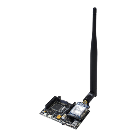
Figure: LoRa module
Figure: LoRa module with 4.5 dBi antenna

-6-
v7.0
Hardware
The user must keep in mind that there are two dierent antennas for LoRa modules regarding the frequency band: 868 or 900
MHz. Although the appearance of these antennas is the same, the user must choose which one needs to be purchased.
Note: It is not recommended to work without an antenna screwed to the module. The module could be damaged due to RF reections.
The frequency used in Europe is the free ISM band of 868 MHz, using 8 channels with a bandwidth of 0.3 MHz per channel. That
is shown in the following gure.
Figure: Frequency channels in the 868 MHz band
Note: These channels were chosen arbitrarily, according to the UN-111 appeared in the Spanish BOE-A-2013-4845. If necessary, users
can select the appropriate channels according to their country regulations.
The frequency used in USA, Canada, Australia, Singapore or Israel is the free ISM band of 900 MHz, using 13 channels with a
bandwidth of 2.16 MHz per channel. It is shown in the following gure.
Figure: Frequency channels in the 900 MHz band
Note: These channels were chosen arbitrarily; they t the channels used by the equivalent XBee 900 MHz. If necessary, users can select
the appropriate channels according to their country regulations.

-7-
v7.0
Hardware
Channel Number Central frequency Channel Number Central frequency
CH_10_868 865.20 MHz CH_00_900 903.08 MHz
CH_11_868 865.50 MHz CH_01_900 905.24 MHz
CH_12_868 865.80 MHz CH_02_900 907.40 MHz
CH_13_868 866.10 MHz CH_03_900 909.56 MHz
CH_14_868 866.40 MHz CH_04_900 911.72 MHz
CH_15_868 866.70 MHz CH_05_900 913.88 MHz
CH_16_868 867 MHz CH_06_900 916.04 MHz
CH_17_868 868 MHz CH_07_900 918.20 MHz
CH_08_900 920.36 MHz
CH_09_900 922.52 MHz
CH_10_900 924.68 MHz
CH_11_900 926.84 MHz
CH_12_900 915 MHz
Figure: Channels used by the LoRa modules in 868 MHz and 900 MHz
Note: Due to the propagation characteristics of the 868/900 MHz bands, the near eld eect could make that 2 modules cannot
communicate if they are placed very close (< 1 m). We suggest to keep a minimum distance of 3 or 4 meters between modules.
Regarding the energy section, the transmission power can be adjusted to several values:
Parameter SX1272 power level
'L' 0 dBm
'H' 7 dBm
'M' 14 dBm
Figure: Transmission power value
Figure: SX1272 output power level

-8-
v7.0
Hardware
The LoRa module uses the SPI pins for communication. The SPI port allows more speed communication and frees up the
Waspmote’s UART for other purposes. The Expansion Board allows to connect two communication modules at the same time
in the Waspmote sensor platform. This means a lot of dierent combinations are possible using any of the radios available for
Waspmote and the LoRa module.
Figure: LoRa module in Socket 0
Note: The SX1272 module can only be used in special Waspmote v12 units which have been modied to drive the SPI pins to socket 0.
The SX1272 module does not implement any security method. Encryption is provided through the Waspmote Encryption
library. Specically, through the AES algorithm with symmetric key, with a length of 128, 192 or 256 bits.
The classic layout of this type of network is Star topology (shown in the gure), as the nodes establish point to point connections
with brother nodes through the use of parameters such as the Node Address.

-9-
v7.0
Hardware
Figure: Star topology
Note: OTA programming is not implemented for the LoRa module. Due to its low datarate, it would take much time to send one
program.

-10-
v7.0
Dual radio with Expansion Board
3. Dual radio with Expansion Board
3.1. Expansion Radio Board
The Expansion Board allows to connect two communication modules at the same time in the Waspmote sensor platform. This
means a lot of dierent combinations are possible using any of the wireless radios available for Waspmote: 802.15.4, ZigBee,
DigiMesh, 868 MHz, 900 MHz, LoRa, WiFi, GPRS, GPRS+GPS, 3G, 4G, Sigfox, LoRaWAN, Bluetooth Pro, Bluetooth Low Energy and
RFID/NFC. Besides, the following Industrial Protocols modules are available: RS-485/Modbus, RS-232 Serial/Modbus and CAN Bus.
Some of the possible combinations are:
• LoRaWAN - GPRS
• 802.15.4 - Sigfox
• 868 MHz - RS-485
• RS-232 - WiFi
• DigiMesh - 4G
• RS-232 - RFID/NFC
• WiFi - 3G
• CAN bus – Bluetooth
• etc.
Remark: GPRS, GPRS+GPS, 3G and 4G modules do not need the Expansion Board to be connected to Waspmote. They can be plugged
directly in the socket1.
Figure: Waspmote with XBee radio on socket0 and Bluetooth Pro module on socket 1

-11-
v7.0
Dual radio with Expansion Board
The LoRa module can be used only in the socket 0. If the user wants to use a wireless radio, they must use the socket 1.
WARNING:
• Avoid to use DIGITAL7 pin when working with Expansion Board. This pin is used for setting the XBee into sleep.
• Avoid to use DIGITAL6 pin when working with Expansion Board. This pin is used as power supply for the Expansion Board.
• Incompatibility with Sensor Boards:
- Agriculture v30 and Agriculture PRO v30: Incompatible with Watermark and solar radiation sensors
- Events v30: Incompatible with interruption shift register
- Gases v30: DIGITAL6 is incompatible with CO2 (SOCKET_2) and DIGITAL7 is incompatible with NO2 (SOCKET_3)
- Smart Water v30: DIGITAL7 incompatible with conductivity sensor
- Smart Water Ions v30: incompatible with ADC conversion
- Gases PRO v30: Incompatible with SOCKET_2 y SOCKET_3
- Cities PRO v30: Incompatible with SOCKET_3. I2C bus can be used. No gas sensor can be used.

-12-
v7.0
General considerations
4. General considerations
4.1. Waspmote libraries
4.1.1. Waspmote SX1272 les
WaspSX1272.h, WaspSX1272.cpp
It is mandatory to include the SX1272 library when using this module. The following line must be introduced at the beginning
of the code:
#include <WaspSX1272.h>
4.1.2. Constructor
To start using the Waspmote SX1272 library, an object from class WaspSX1272 must be created. This object, called sx1272,
is created inside the Waspmote SX1272 library and it is public to all libraries. It is used through the guide to show how the
Waspmote SX1272 library works.
When creating this object, some variables are dened with a value by default.
4.2. API functions
Through the guide there are many examples of using parameters. In these examples, API functions are called to execute the
commands, storing in their related variables the parameter value in each case.
Example of use:
{
sx1272.getPreambleLength(); // Gets the preamble length that is going to be send
}
Related variables:
sx1272._preamblelength →stores the preamble length
When returning from sx1272.getPreambleLength() the variable sx1272._preamblelength will be lled with the
appropriate values.
Before calling the function, the related variable is created but it is empty.
All the functions return a ag to know if the function called was successful or not. Available values for this ag:
• 0 : Success. The function was executed without errors and the variable was lled.
• 1 : Error. The function was executed but an error occurred while executing.
• 2 : Not executed. An error occurred before executing the function.
• -1 : Function not allowed in this mode.

-13-
v7.0
General considerations
The main functions are listed here:
Basic functions
WaspSX1272(); Class constructor.
ON(); Opens the SPI and switches the SX1272 module on.
OFF(); Closes the SPI and switches the SX1272 module o.
readRegister(); Reads the indicated internal register.
writeRegister(); Writes the indicated internal register.
clearFlags(); Clears the interruption ags.
Conguration functions
setLORA(); Sets the module in LoRaTM transmission mode.
getMode(); Gets the BW, CR and SF of the LoRaTM modulation.
setMode(); Sets the BW, CR and SF of the LoRaTM modulation.
getHeader(); Indicates if module is congured in implicit or explicit header
mode.
setHeaderON(); Sets the module in explicit header mode (header is sent).
setHeaderOFF(); Sets the module in implicit header mode (header is not sent).
getCRC(); Indicates if module is congured with or without checking
CRC.
setCRC_ON(); Sets the module with CRC on.
setCRC_OFF(); Sets the module with CRC o.
getChannel(); Indicates the frequency channel within the module is
congured.
setChannel(); Sets the indicated frequency channel in the module.
getPower(); Gets the signal power within the module is congured.
setPower(); Sets the signal power indicated in the module.
setPowerNum(); Sets the signal power indicated in the module.
getPreambleLength(); Gets the preamble length from the module.
setPreambleLength(); Sets the preamble length in the module.
getPayloadLength(); Gets the payload length from the module.
setPacketLength(); Sets the packet length in the module.
getNodeAddress(); Gets the node address in the module.
setNodeAddress(); Sets the node address in the module.
setRetries(); Sets the maximum number of retries.
getMaxCurrent(); Gets the current supply limit of the internal power amplier.
setMaxCurrent(); Limits the current supply of the internal power amplier.
getTemp(); Gets the temperature from the measurement block module.
getRegs(); Gets the content of dierent registers.

-14-
v7.0
General considerations
Link information functions
getSNR(); Gets the SNR value in LoRaTM mode.
getRSSI(); Gets the current value of RSSI from the channel.
getRSSIpacket(); Gets the RSSI of the last packet received in LoRaTM mode.
Sending functions
sendPacketTimeout(); Sends a packet to the specied destination before a timeout
expires.
sendPacketMaxTimeout(); Same as previous function with maximum timeout.
sendPacketTimeoutACK(); Sends a packet to a destination before a timeout and wait for
an ACK response.
sendPacketMaxTimeoutACK(); Same as previous function with maximum timeout.
sendPacketTimeoutACKRetries(); Sends a packet to a destination before a timeout, wait for an
ACK response and retry to send the packet if ACK is lost.
sendPacketMaxTimeoutACKRetries(); Same as previous function with maximum timeout.
Receiving functions
receivePacketTimeout(); Receives information before a timeout expires.
receivePacketMAXTimeout(); Same as previous function with maximum timeout.
receivePacketTimeoutACK(); Receives information before a timeout expires and responds
with ACK.
receivePacketMAXTimeoutACK(); Same as previous function with maximum timeout.
receiveAll(); Receives all the information on air with maximum timeout.
showFramefromPacket(); Prints a frame received in a packet.
4.3. Additional functions
4.3.1. Getting temperature
It reads the module temperature in Celsius. Negative temperatures can be expected. It stores the information in the global
_temp variable in Celsius.
Note: this feature has not a good accuracy because it requires internal calibration. Libelium recommends to use dedicated temperature
sensor.
Example of use:
{
sx1272.getTemp(); // Gets the temperature of the module
}
Related variables:
sx1272._temp →stores the temperature of the module
SX1272 getting temperature example:
www.libelium.com/development/waspmote/examples/sx-13-get-temp

-15-
v7.0
General considerations
4.3.2. Getting maximum allowed current supply
It reads the current supply limit of the power amplier. This value is set to 240 mA at the beginning of the conguration when
the module is switched on. Parameter range: from 0x00 to 0x1B corresponding to a range from 45 to 240 mA.
Example of use:
{
sx1272.getMaxCurrent(); // Gets the maximum current supply
}
Related variables:
sx1272._maxCurrent →stores the maximum current supply of the module
SX1272 getting current supply example:
www.libelium.com/development/waspmote/examples/sx-14-currentsupply
4.4. Waspmote reboot
When Waspmote is rebooted, the application code will start again, creating all the variables and objects from the beginning.

-16-
v7.0
Transmission modes
5. Transmission modes
The module has two dierent modulations, LoRa™ modulation, owned by Semtech, and standard FSK modulation. Libelium has
decided to only use the LoRa™ modulation due to the range improvement it provides.
When setting the SX1272 module on, the module is prepared to use LoRa mode.
About the operation states, it is not necessary to control them manually. It is done automatically by the API functions.
5.1. LoRaTM mode
The innovative LoRa™ mode is the most interesting included in this module. It is an advanced and private modulation that
increases the range comparing to classic modulations. The LoRa™ long range mode provides ultra-long range spread spectrum
communication and high interference immunity whilst minimizing current consumption. It combines digital spread spectrum,
digital signal processing, and forward error correction coding to achieve unprecedented performance. LoRa™ also provides
signicant advantages in both blocking and selectivity over conventional modulation techniques.
LoRa has three congurable parameters:
• Bandwidth (BW)
• Coding Rate (CR)
• Spreading Factor (SF)
The combination of these values denes the transmission mode. It is possible to set a predened mode or to set these three
parameters manually.
There are ten predened modes in the API, including the largest distance mode, the fastest mode, and eight other intermediate
modes that Libelium has found interesting. All of them can be modied or deleted, and also it is possible to attach new modes
in the appropriate function. The predened modes and its properties are shown in the next table.
Mode BW CR SF Sensitivity
(dB)
Transmission time
(ms) for a 100-byte
packet sent
Transmission time
(ms) for a 100-byte
packet sent and
ACK received
Comments
1 125 4/5 12 -134 4245 5781 max range, slow
data rate
2 250 4/5 12 -131 2193 3287 -
3 125 4/5 10 -129 1208 2120 -
4 500 4/5 12 -128 1167 2040 -
5 250 4/5 10 -126 674 1457 -
6 500 4/5 11 -125,5 715 1499 -
7 250 4/5 9 -123 428 1145 -
8 500 4/5 9 -120 284 970 -
9 500 4/5 8 -117 220 890 -
10 500 4/5 7 -114 186 848
min range, fast
data rate, minimum
battery impact
Figure: LoRa conguration modes
The transmission times have been measured for a whole transmission process: power the module on, congure the module,
send a 100-byte packet and power the module o.
The user will be able to choose the most suitable mode for that application after the appropriate test phase because there is not
a perfect mode for any situation. In fact, it exists a compromise between distance range and speed of transmission.

-17-
v7.0
Transmission modes
Note: When transmitting in ISM frequency bands, the user must ensure that the communication is not exceeding the permitted time
using the chosen frequency channel (for example, 1% of time). It is the responsibility of the user to know the allowed time of use in the
occupied frequency band and respect it. Ignoring this, could lead to considerable penalties.
Example of use:
{
sx1272.setMode(3); // Sets the LoRa mode in transmission mode 3
}
SX1272 conguration example:
www.libelium.com/development/waspmote/examples/sx-01-congure-lora-parameters
If the user is going to select a mode with this function, it is not necessary to set also the bandwidth, coding rate and spreading
factor later.
5.1.1. Bandwidth
The value of the bandwidth shows how wide is going to be the transmission signal. It only can be chosen among 3 options:
125 kHz, 250 kHz or 500 kHz. If a fast transmission is required, a 500 kHz value is better. But if a great reach is needed, a 125 kHz
value must be congured. The smaller the bandwidth is, the higher the time-on-air is in a transmission but also the better the
sensitivity is, so the communication has better link budget. The user should also note that the increasing in time-on-air involves
an increasing in battery consumption.
Example of use:
{
sx1272.setBW(BW_250); // Sets the 250 kHz bandwidth in LoRa mode
}
5.1.2. Coding Rate
The coding rate value must be chosen among 4 options: 4/5, 4/6, 4/7 and 4/8. It denotes that every 4 useful bits are going to be
encoded by 5, 6, 7 or 8 transmission bits depending on its value. The smaller the coding rate is (the smallest is 4/8), the higher
the time-on-air is in a transmission, so it takes more time to transmit a packet. This will ease the task of receiving, because each
symbol is wider in time, so the receiver can demodulate packets with lower reception power. This means the receiver has better
sensitivity, so the user has better link budget. But slow data transmissions have an impact in the battery consumption: spending
more time in transmission mode involves more battery consumption.
Example of use:
{
sx1272.setCR(CR_7); // Sets the 4/7 coding rate in LoRa mode
}
5.1.3. Spreading Factor
The spreading factor is the number of chips per symbol used in the data treatment before the transmission signal. Its value is
an integer number between 6 and 12. This parameter is relevant in the spread spectrum technique. In the spread spectrum
techniques, the greater value of this parameter, the more capability the receiver has to move away the noise from the signal.
So the greater value taken, the more time it takes to send a packet, but also the better range is reached because the receiver
sensitivity is better.
Example of use:
{
sx1272.setSF(SF_9); // Sets the 9 spreading factor in LoRa mode
}

-18-
v7.0
Initialization
6. Initialization
Before starting to use a module, it needs to be initialized. During this process, Waspmote’s SPI bus has to be opened to
communicate with the module, and the LoRa module’s switch has to be set on.
Note: This module does not save the conguration. So, the network settings as the mode or the channel MUST be congured
every time it is switched on.
6.1. Setting on
It initializes all the global variables, opens the SPI bus and switches the LoRa module on.
When setting on, the module always has the conguration by default shown in the next table:
Global variable Description Initial value
modem activated mode LORA
bandwidth bandwidth to use in LoRaTM mode BW_125
codingRate coding rate to use in LoRaTM mode CR_5
spreadingFactor spreading factor to use in LoRaTM mode SF_7
channel transmission frequency channel CH_12_900
header species if header is enabled HEADER_ON
CRC species if CRC is enabled CRC_OFF
power power transmission level 15
Figure: Conguration by default
Also, there are other global variables initialized when this function is called, shown in the following table:
Global variable Description Initial value
packetNumber packet number to send 0
reception species if packet is correctly received CORRECT_PACKET
retries number of the current retrying that is
being executed in the protocol 0
maxRetries maximum number of retries permitted
in each case 3
Figure: Global variables initialized by software
Example of use:
{
sx1272.ON(); // Opens the SPI and switches the SX1272 module ON
}
6.2. Setting o
It closes the SPI and switches the SX1272 module o.
Example of use:
{
sx1272.OFF(); // Closes the SPI and switches the SX1272 module off
}

-19-
v7.0
Node parameters
7. Node parameters
When conguring a node, it is necessary to set some parameters which will be used lately in the network, and some parameters
needed for using the API functions.
7.1. Node address
Each module must have a unique address of 8 bits.
It identies uniquely a node inside a network. It is necessary to assign the address value each time the module is set on.
The node address 0 and the node address 1 are reserved to broadcast communication and to the network central node
respectively. In order to respect this, users must assign the node address 1 to the module in the central node and node addresses
from 2 to 255 to all the other nodes in their network. That means a network will consist of:
• 1 central node. Address value equal to 1
• Up to 254 nodes. Address values from 2 to 255
The user must not assign the node address 0 to any node since it is reserved to indicate the module we want to perform a
broadcast transmission.
Example of use:
{
sx1272.setNodeAddress(2); // Set the Node address into REG_NODE_ADDRESS register
sx1272.getNodeAddress(); // Get the assigned Node address
}
Related variables:
sx1272._nodeAddress →stores the Node address
The module rejects packets destined to other nodes, although it is actually receiving all the packets in the network while it is in
receiving state.
7.2. Frequency band
There are two frequency bands available to work with this module, 868 MHz and 900 MHz ISM bands. Depending on the country
the user is located, one or the other will be chosen. Inside each frequency band there are several channels, so the user can
choose among them.
Note: To know what band is legal in your country, please check the ITU region map. Region 1 ISM free band is 868 MHz and Region
2 ISM free band is 900 MHz. You must also check the legal restrictions by region to use the proper conguration and channel. It is the
responsibility of the users to know the allowed frequency band and channels in their country, and use them. Ignoring this, could lead
to considerable penalties.

-20-
v7.0
Node parameters
7.3. Channel
This parameter denes the frequency channel used by the module to transmit and receive.
There are 8 channels dened to be used in the 868 MHz band and 13 channels to be used in the 900 MHz band. They can be
observed in the following gures.
Figure: Frequency channels in the 868 MHz band
Figure: Frequency channels in the 900 MHz band
Channel Number Central Frequency Channel Number Central Frequency
CH_10_868 865.20 MHz CH_00_900 903.08 MHz
CH_11_868 865.50 MHz CH_01_900 905.24 MHz
CH_12_868 865.80 MHz CH_02_900 907.40 MHz
CH_13_868 866.10 MHz CH_03_900 909.56 MHz
CH_14_868 866.40 MHz CH_04_900 911.72 MHz
CH_15_868 866.70 MHz CH_05_900 913.88 MHz
CH_16_868 867 MHz CH_06_900 916.04 MHz
CH_17_868 868 MHz CH_07_900 918.20 MHz
CH_08_900 920.36 MHz
CH_09_900 922.52 MHz
CH_10_900 924.68 MHz
CH_11_900 926.84 MHz
CH_12_900 915 MHz
Figure: Channels used by the LoRa modules in 868 MHz and 900 MHz
Table of contents
Other Libelium Control Unit manuals
Popular Control Unit manuals by other brands

Victaulic
Victaulic 809N installation instructions

Meinberg
Meinberg IMS-GPS180 manual

tiki
tiki SHB10 Installation and user manual

Silicon Laboratories
Silicon Laboratories BGM220SC22 user guide

Eaton
Eaton COOPER POWER SERIES Installation and operation instruction

Mitsubishi Electric
Mitsubishi Electric MELSEC QJ71PB92D user manual