©Copyright 2012 Liberty Pumps Inc. All rights reserved. 8
3-6 CONNECTION TO ELECTRICAL SUPPLY
3-6-1 All wiring should be done in accordance with the applicable electrical codes. The macerating system requires a single-phase, 120
volt, 15-amp GFCI (ground fault circuit interrupter) type receptacle. Receptacle should be installed in accordance with local and
state electrical codes. It is recommended that the receptacle be 40 inches away (in a straight line) from a shower or bathtub. If
installation is performed in a basement, the receptacle should be 48 inches from the floor.
3-6-2 If the electrical power receptacle (outlet) is in close proximity to the macerator, the “extra power cord” can be coiled and tucked
away in a large depression designed into the access cover that is located under the right decorative cover.
Risk of electric shock. This pump is supplied with a
grounding-type attachment plug. To reduce the risk of
electric shock, be certain that it is connected to a
properly grounded, grounding-type receptacle.
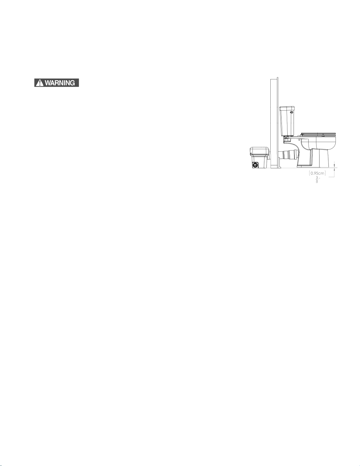
3-7 EXTENSION PIPE
3-7-1 For installations where the macerator is located behind a wall, an extension pipe kit
K001184 will be needed (sold separately). The extension pipe is 16” long. One end
slips inside the macerator and the other end slips over the toilet’s discharge. A rubber
ring seals both ends of the extension pipe. No fasteners are required - just slide the
parts together. The toilet is fastened to the floor and the discharge and vent piping
secure the macerator. The toilet should be raised by at least 3/8” to facilitate
proper gravity flow toward the macerator box. See schematic.
3-7-2 Liberty recommends only one extension pipe be used.
3-8 INSTALLATION TIPS
3-8-1 PIPE SUPPORTS
All sanitary pipe work must be supported in accordance with the pipe manufacturer’s recommendations. Avoid dipping or trapping,
which may cause the buildup of residual “solids” and subsequent blockage.
3-8-2 BENDS
Wherever possible, long sweeping bends should be used. Do not use short elbows. If sweeping 90° elbows are not available, use
two 45° elbows to make a 90° turn.
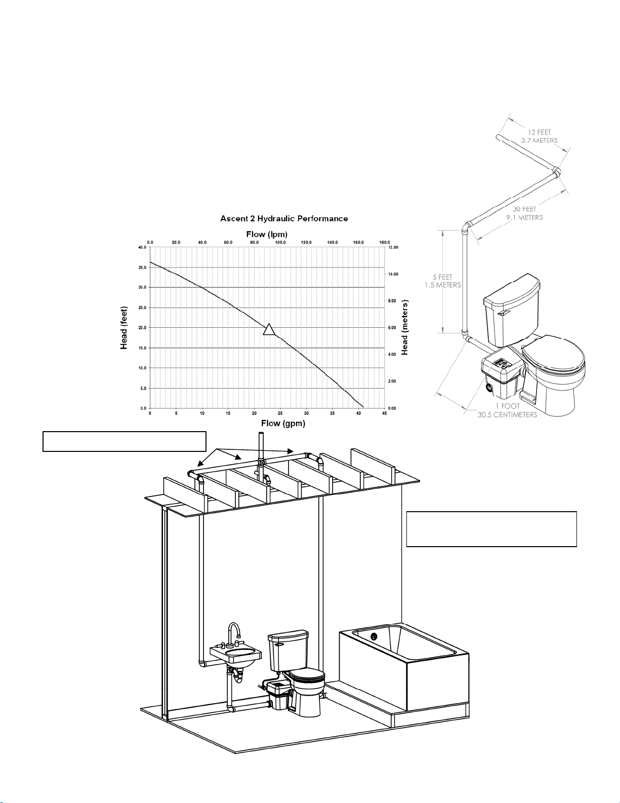
3-8-3 VERTICAL PIPING FIRST
If vertical lift is required, this must precede the horizontal pipe run.
3-8-4 DIRECTLY VERTICAL
All vertical lifts should rise as close to the macerator as possible, allowing only for the need to clear the toilet tank; the initial
horizontal run should not exceed 12”.
3-8-5 NO DIAGONAL “UPHILL” PIPE RUNS
All discharge piping from the unit should run either directly vertical or in a horizontal plane (with a minimum ¼” per foot drop) to the
point of discharge. Pipe work must not be installed with a diagonal upward slope from the unit to the point of discharge.
3-8-6 EASY ACCESS
The unit should be accessible and removable in the event of maintenance being required. During the installation, a full-port ball
valve should be installed near the discharge flange to allow easy service of the unit.
3-8-7 GRAVITY FALL
The unit accepts wastewater by gravity; it does not “vacuum” in water. All inlet pipe work must have a positive gravity fall (1/4” per
foot drop minimum). All horizontal piping from the macerator must also have a ¼” per foot drop to allow free drainage when the
pump stops.
3-8-8 SOIL STACK CONNECTION
All discharge pipe work must be connected to the soil stack by an appropriate and approved connection like a “tee” or “y” fitting.
3-8-9 PIPE WORK
All pipe work should be copper, PVC, or CPVC. Do not use flexible piping. Hangers should not be less than 4 feet apart to prevent
pipe rattling.
3-8-10 FLUSHING
Macerator is designed to work with a low flow toilet (1.28 gallons per flush).
3-8-11 DISCHARGE
Never discharge directly into an open drain, fixture, manhole or rainwater drainpipe. It is illegal, as it constitutes a health hazard.
Direct connections into sanitary waste systems only shall be acceptable.
3-8-12 FREEZING
Ensure all pipe work susceptible to freezing is adequately insulated or heated. In unheated buildings, the toilet, piping and
macerating unit must be properly winterized. Use plumbers’ anti-freeze or drain completely.