– 6 – Copyright © Liberty Pumps, Inc. 2018
All rights reserved. 5755000H
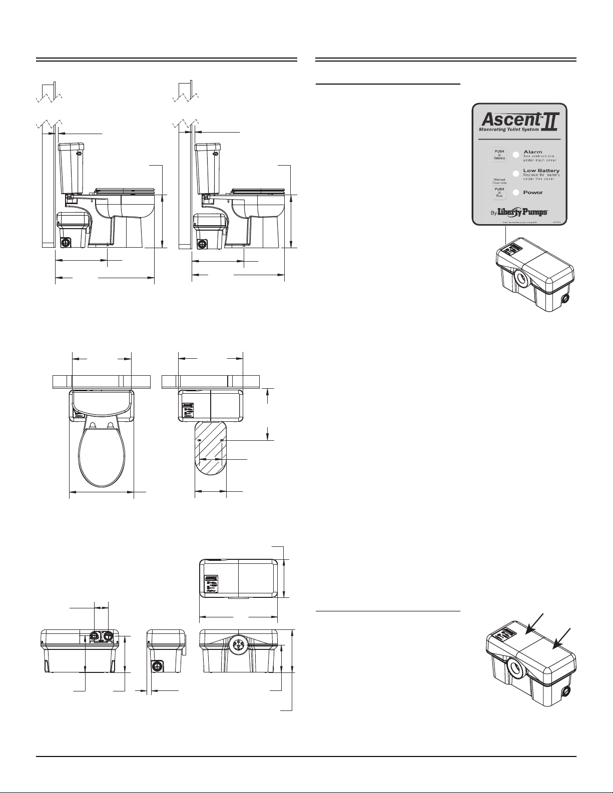
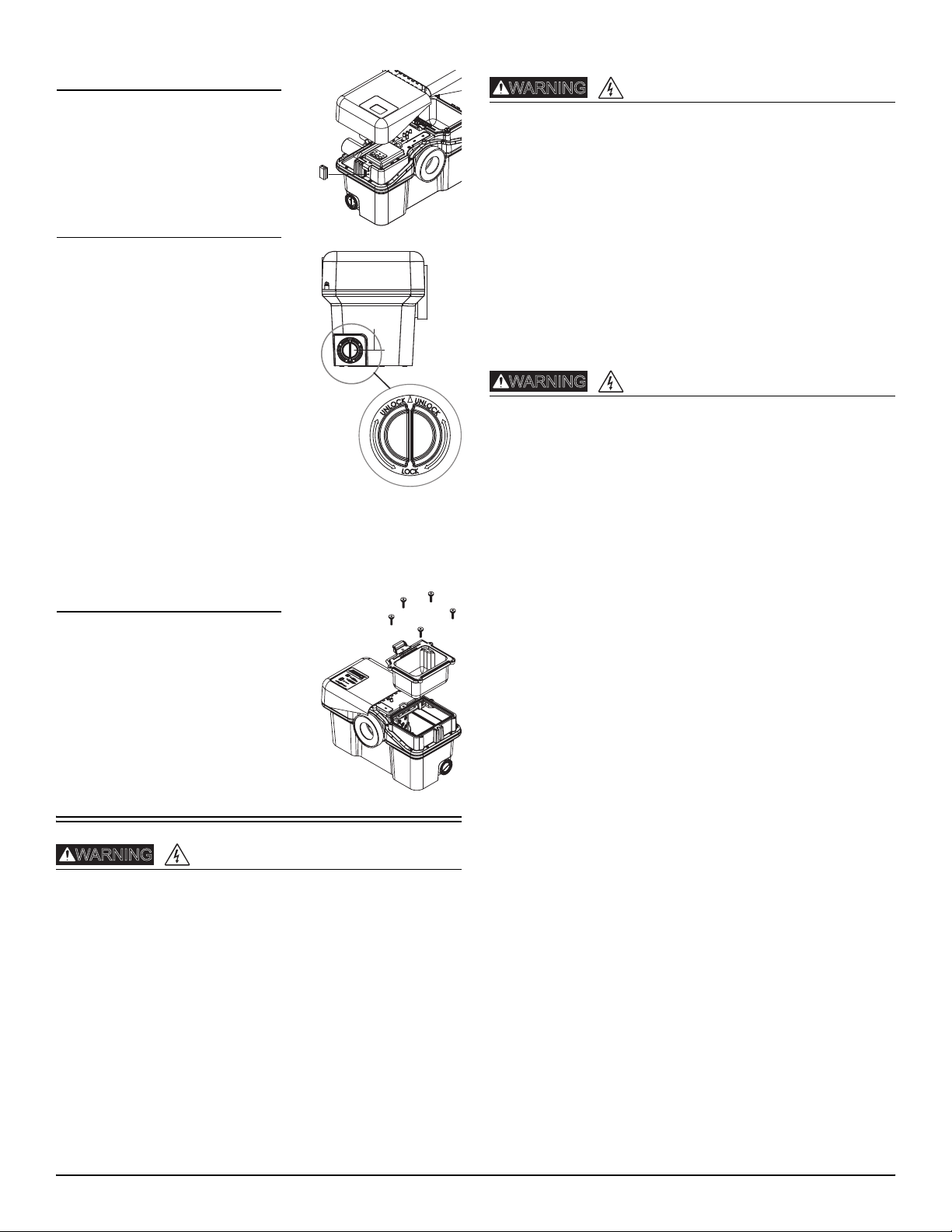
Battery Access
The battery receptacle is accessible
under the left decorative cover. Do not
install battery until the unit has been
installed, connected, and ready for
operation.
Auxiliary Inlets
The macerator unit is equipped with
two inlet ports, one on each side.
These ports are designed for standard
PVC pipe. Included with the system are
two 2” flexible PVC couplers and
1-1/2” reducing bushings. These inlets,
which incorporate an internal check
valve, are used to connect the
drainpipe of other sanitary fixtures to
the macerating pump unit.
Typically, the 2” drain is used with
shower stalls only. A tub, shower/tub
combo, or sink would use a 1-1/2”
drain line. From the factory, the
auxiliary inlets are plugged; if the port
is to be used, the plug must be removed by rotating until the rib is
vertical and then pulling outward. If the unit has been stored for
some time, pliers may be needed to assist in removal.
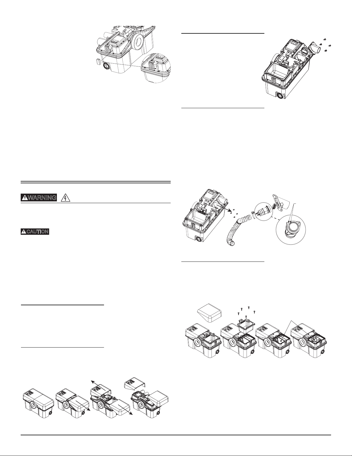
Access Cover
The macerator has an access cover that
can be removed to gain access to the
pumping and macerating cartridge to
remove debris or perform service. The
auxiliary inlet couplers, Allen wrench,
grease packet, clamps, and 9V battery
are shipped in the access cover
beneath the right access cover.
Preparation
The pump shall be plugged into a properly fused electrical
outlet with a ground fault circuit interrupter (GFCI) that
conforms to current National Electric Code (NEC) and all
applicable local codes. All wiring must be performed by
qualified personnel.
Pump shall be properly grounded using its supplied
grounding conductor. Do not bypass grounding wires or
remove ground prong from attachment plugs. Failure to
properly ground the pump system can cause all metal
portions of the pump and its surroundings to become
energized.
The electrical power supply shall be located within the length
limitations of the pump power cord, and for below grade
installations, it shall be at least 4 ft (1.22 m) above floor level.
Do not use an extension cord to power the product.
Extension cords can overload both the product and extension
cord supply wires. Overloaded wires will get very hot and can
catch on fire.
Explosion hazard during installation. PVC cleaners, primers,
and cements can release explosive vapors. These
heavier-than-air vapors can accumulate in the tank. The heat
of soldering or sweating copper or other metal pipe can
ignite these vapors causing a violent explosion. If the unit is
to be connected to copper discharge or vent piping, all
solvent-welded PVC joints must be allowed to cure a
minimum of 24 hours. The access cover must be removed to
allow the tank to be thoroughly ventilated prior to sweating
copper pipe near the unit.
Do not modify the pump/pump system in any way.
Modifications may affect seals, change the electrical loading
of the pump, or damage the pump and its components.
All pump/pump system installations shall be in compliance
with all applicable Federal, State, and Local codes and
ordinances.
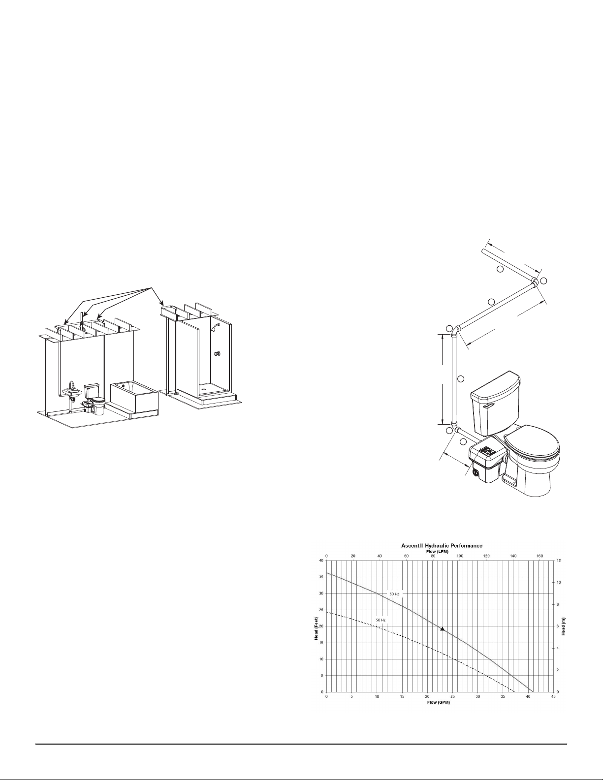
Layout: The bathroom layout should be designed prior to
installation. Make certain the power source (GFCI receptacle) is
within range of the macerator’s 8 ft power cord. The GFCI
receptacle shall be 40 inches away (in a straight line) from a
shower or bathtub. For basement installation, the receptacle shall
be 48 inches from the floor.
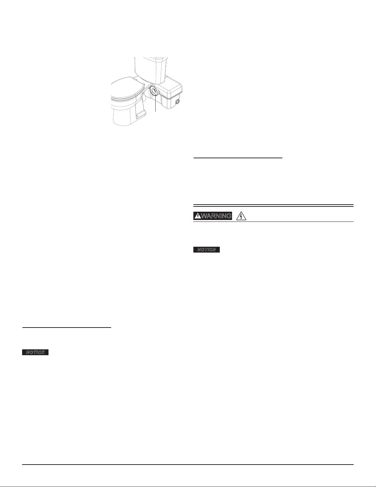
Power Cord: The power cord can be configured to exit the unit on
either the left or right side. If the power cord will exit the left side
of the macerator, the vent flange must be removed so the cord
can be routed between the positioning clips. Reinstall vent flange
after routing the cord. Do not use an extension cord. If the
electrical power receptacle (outlet) is in close proximity to the
macerator, any extra power cord can be coiled and tucked away in
the access cover located under the right decorative cover.
Easy Access: The unit should be accessible and removable in the
event of required maintenance. During installation, a full port ball
valve should be installed near the discharge flange to allow easy
service of the unit. If possible, the right side of the macerator
should remain unobstructed. The access cover allows access to
the internal mechanisms. In the event of a jam, the decorative
cover as well as the access cover will need to be removed from the
macerator and working room to do so would be beneficial.
Water Supply: The water supply line for the toilet tank is located
on the left side. When roughing in, allow for the macerator.
Discharge: Never discharge directly into an open drain, fixture,
manhole or rainwater drainpipe. It is illegal, as it constitutes a
health hazard. Only direct connections into sanitary waste systems
shall be acceptable.
Auxiliary Ports: Auxiliary inlet ports are located on either side
toward the back of the macerator tank. These ports can accept
waste from sink or tub/shower. A sink should be plumbed into
one of the auxiliary inlets and not the discharge line of the
macerator even if elevations would allow such an installation. The
discharge line is pressurized and the plumbing system needs to
accommodate this.
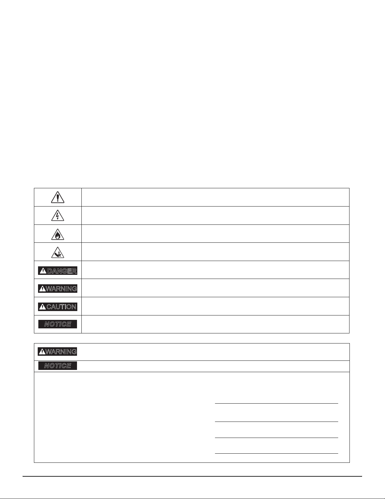
RISK OF ELECTRIC SHOCK
RISK OF FIRE
RISK OF SERIOUS INJURY OR DEATH