Liebert UPStation S VCR232CR Quick guide

POWER PROTECTION
UPStation®S
VCR232C/VCR232CR Option
RS-232 with Summary Alarm
3.5 kVA through 18 kVA
Installation & Instruction
Manual
DISCONTINUED
PRODUCT

DISCONTINUED
PRO DU C T

i
TABLE OF CONTENTS
IMPORTANT SAFETY INSTRUCTIONS . . . . . . . . . . . . 1
1.0 INTRODUCTION
2.0 INSTALLATION
3.0 SYSTEM SETUP
DISCONTINUED
PRO DU C T

ii
FIGURES
DISCONTINUED
PRO DU C T

1
IMPORTANT SAFETY INSTRUCTIONS
DISCONTINUED
PRO DU C T

2 Introduction
1.0 INTRODUCTION
1.1 Description
DISCONTINUED
PRO DU C T

Introduction 3
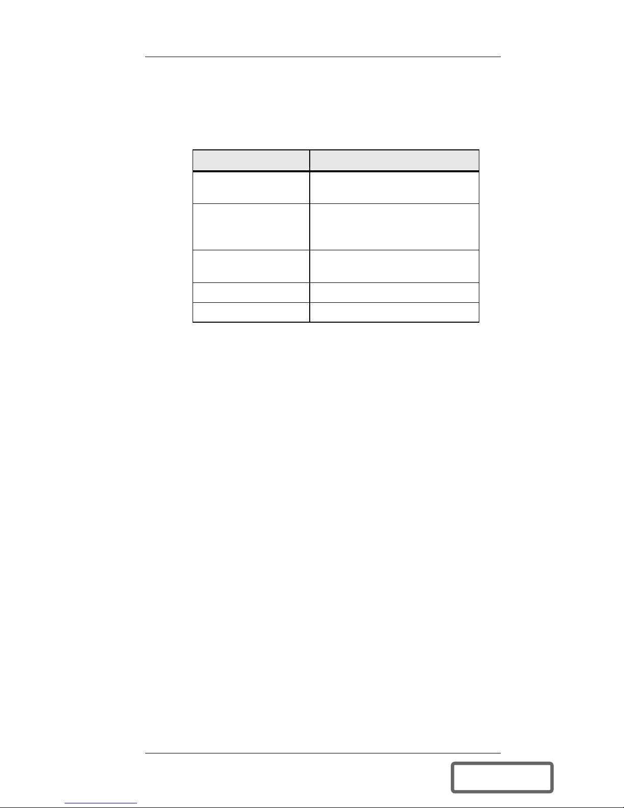
1.1.1 RS-232 Serial Communications
Modem/Host Computer/Terminal
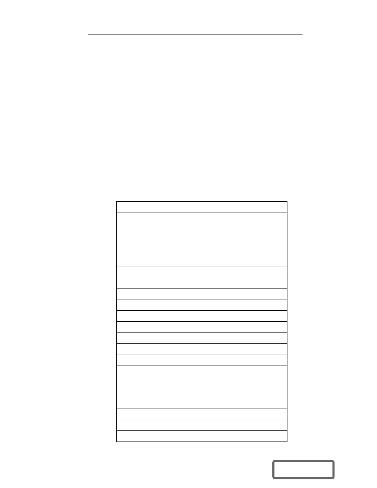
Battery failed test
Battery SCR fault (shoe or open)
Bypass shutdown due to overload (UPS shutdown)
Charger shutdown due to over temperature
Control power supply failure
DC bus under voltage
Excessive retransfer attempts
Inverter shutdown due to overcurrent
Inverter shutdown due to overload
Inverter shutdown due to overtemperature
Inverter shutdown due to under/over voltage
Low battery
On battery
PFC fault (hardware fault)
PFC shutdown due to over temperature
PFC voltage high
PFC voltage low
RAM test failed
ROM test failed
Time-out fault (self test at start-up)
UPS fault
User initiated UPS shutdown
DISCONTINUED
PRO DU C T

4 Introduction
1.1.2 Contact Closures & AS/400
1.1.3 Programmable Relays
DISCONTINUED
PRO DU C T

Introduction 5
1.2 Contents
1.3 Tools Required
Part Purpose
25' Cable with one
RJ45 connector
For customer use
13" Cable with two
RJ45 connectors
For internal (metal plate to
VCR232C/VCR232CR)
connection
RS-232C Printed
Circuit Board
Plugs Into existing
microprocessor board
Back Plate Replaces existing metal plate
Manual Installation and Instructions
DISCONTINUED
PRO DU C T

6 Installation
2.0 INSTALLATION
2.1 Safety Precautions
Figure 1 Location of Protective Breakers, Fuses
DISCONTINUED
PRO DU C T

Installation 7
2.2 Top Cover Removal
Figure 2 Top Cover Retaining Screws
2.3 EMI Shield Removal
Figure 3 EMI Shield Removal
DISCONTINUED
PRO DU C T

8 Installation
2.4 Metal Option Plate Removal
Figure 4 Option Plate Removal
2.5 VCR232C/VCR232CR Installation
Figure 5 J6 Location on Microprocessor Board
DISCONTINUED
PRO DU C T

Installation 9
Figure 6 Proper Alignment of VCR232C/VCR232CR
Board With J6
Figure 7 Installing New Option Plate
DISCONTINUED
PRO DU C T

10 Installation
2.6 Cable Connections
Blue Relay 1 Common
Orange Relay 1 NC
Black Relay 1 NO
Red Relay 2 Common
Green Relay 2 NC
Yellow Relay 2 NO
Brown No Connection
Grey No Connection
DISCONTINUED
PRO DU C T

Installation 11
2.7 Closing Up the Unit
Figure 8 Replacing the EMI Shield
Figure 9 Replacing Top Cover
DISCONTINUED
PRO DU C T

12 Installation
2.8 Applying Power After Installation
DISCONTINUED
PRO DU C T

System Setup 13
3.0 SYSTEM SETUP
3.1 Programming the Configurable Relays
Figure 10 Steps in Defining Configurable Relays
DISCONTINUED
PRO DU C T

14 System Setup
3.2 System Setup
Figure 11 Configuring a Relay to Respond to Alarms
DISCONTINUED
PRO DU C T

System Setup 15
3.3 Placing the Unit Back Online
3.4 Technical Assistance
DISCONTINUED
PRO DU C T

16 System Setup DISCONTINUED
PRO DU C T
This manual suits for next models
1
Table of contents
Other Liebert Accessories manuals
Popular Accessories manuals by other brands

P3 International
P3 International Wicked Colors Q1048 user guide

PCB Piezotronics
PCB Piezotronics 103B12 Installation and operating manual

CAS
CAS WEIGHING SOLUTION NT-200 Series manual

Pepperl+Fuchs
Pepperl+Fuchs IPT FP Series manual

Sharper Image
Sharper Image 207108 user guide

Digi-Pas
Digi-Pas DWL5000XY Installation and Operation Guidelines