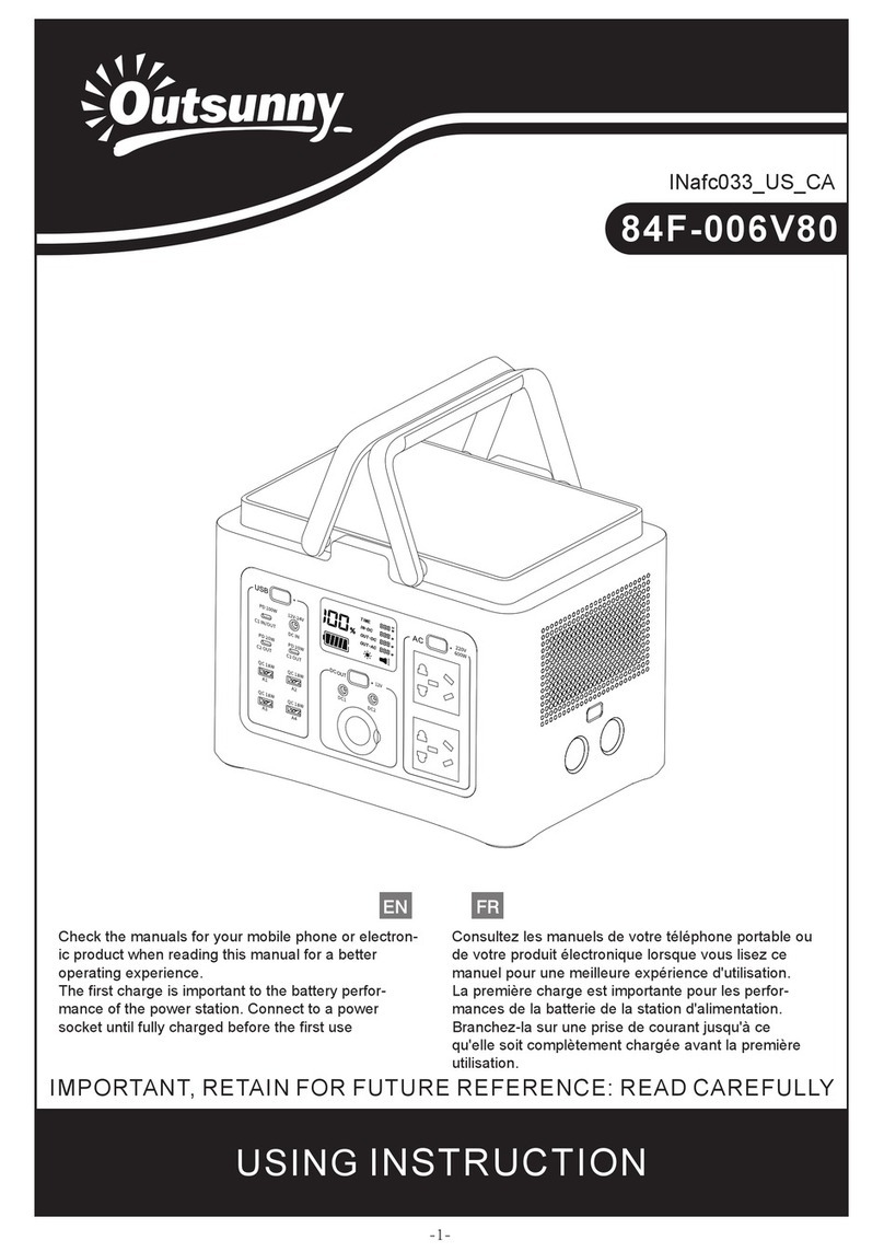
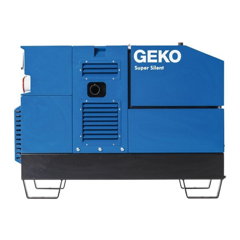
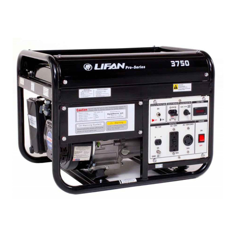
Lifan 2.8GF-3/4 User manual

PREFACE
Thank you for choosing a gasoline generator set by our Co.
Based on the latest technology at home and abroad, our Co. has successfully developed the gasoline
generator set. The unit is characterized by advanced design, compact structure, reliable performance,
convenient service, low fuel consumption and noise as well as fashion shape. With general gasoline engine as
power, it is widely used in many fields such as living, open working, shop, bank, fishing and so on.
The manual gives information with respect to operation and maintenance of the gasoline generator, and be
sure to read it carefully first before operating. If any trouble occurs, call your dealer who will provide you with
the best after service.
All the materials and diagrams of this manual are in accordance with the newest products at the publishing
time. Due to revision and other change, the information descried in this manual may be a little different from
the actual stares. The copyright of this manual belongs to our Co., any group or individual is forbidden to
reprint or copy any it. The manual is subject to change without notice.
1

IMPORTANT NOTICES
Please pay special attention to statements preceded by the following words:
WARNING:
A warning is used to alert the user to fact that hazardous operating and maintenance procedures
may result in injury to or death of personnel if not strictly observed.
CAUTION:
A caution is used to alert the user to fact that hazardous operation and maintenance procedures
may result in injury to or death of personnel if not strictly observed.
NOTE:
Give helpful information.
This manual should be considered as a permanent part of the unit and should remain with the unit when
resold.
2

Contents
1. Generator Safety……………………………………………………………………………………………4
2. Introduction to Parts and Components ……………………………………………………………………6
3. Pre-Operating Inspection …………………………………………………………………………………7
4. Starting the Engine…………………………………………………………………………………………11
5. Service ……………………………………………………………………………………………………13
6. Stopping the Engine ………………………………………………………………………………………18
7. Maintenance ………………………………………………………………………………………………19
8. Storage ……………………………………………………………………………………………………23
9. Troubleshooting……………………………………………………………………………………………25
10.Assembly of parts…………………………………………………………………………………………27
11. Specifications ……………………………………………………………………………………………29
12. Wiring Diagram …………………………………………………………………………………………30
3

1. GENERATOR SAFETY
1.1Neveroperateit
inanenclosedroom.
Fig.3
Fig.1 1.2Neverconnecttohomecircuit.
Fig.2 Fig.4
1.3 Do not operate it under wet circumstances. 1.4 Place inflammables away from the unit at
least one meter.
4

1.5Nosmokingwhenfillingfuel.
Fig.5
Fig.6
1.6 Always fill fuel after stopping it.
Fig.7
1.7 Do not spill out when filling fuel.
5

2.INTROUCITON TO PARTS AND COMPONENTS
Main components of the unit are located as follows.
1.Fuel sensor
2. Fuel filler cap
3. AC plug socket
4. AC breaker
5. Voltmeter
6. Dipstick
7. Ignition switch
8. Drain plug
9. Starting handle
10. Fuel cock
11. Air cleaner
12. Choke lever
13.Groundterminal
14. Muffler
15.Sparkplug Fig.8
6

3. PRE-OPERATING INSPECTION
3.1 ENGINE-OIL LEVEL
NOTE: always check the generator in the case of stopping the generator on a level ground.
1. Turn out the oil
filler cap and clean
the dipstick with
a clear clothe.
Fig.9
2. Insert the dipstick
back into the oil filler
hole without turning
it in.
Fig.10
3. In the case that the oil
ever is below the lower
level mark of the dipstick,
fill oil to the upper level
mark of the dipstick.
Fig.11
4. Reinstall the oil filler
cap well.
Fig.12
7

3.2 FUEL LEVEL
1. Open the fuel filler cap.
Fig.13
2. Check the fuel level, and fill fuel if necessary.
Fig.14
3. Fill fuel to the shoulder of the filter.
Fig.15
. Reinstall the fuel filler cap well.
Fig.16
4
3.3 AIR CLEANER
8

1. Remove the clip and dismantle the air housing
ig.17
. If the core is filthy, clean it in the following
drops of engine oil into it.
.
Fig.19
Fig.18
2. Check and make sure the air cleaner core is intact
and clean. If it is broke, replace it with a new one.
F
4. Put the filter element in to the original position,
install the cover and secure it well.
3
sequence.
a) Clean the core in the cleansing solvent.
b) Dry it up
c) Dip a few
d) Squeeze excess oil
3.4 BATTERY (2.8GF-4、4GF-4 & 5GF-4)
9

Check and make sure that the electrolyte level of each battery cell is between is upper and lower level
marks.
Fig.20
. upper level mark 2. lower lever mark
1
10

4. STARTING THE GENERATOR
4.1 Remove all loads from AC socket.
4.2 Switch off the AC breaker.
Fig.21
4.3 Turn on the fuel cock.
Fig.22
4.4 Set the choke lever to OFF position.
Don’t close the choke when starting the engine in
hot condition.
Fig.23
11

4.5Turnontheignitionswitch.
Fig.24
4.7 Once the engine is warmed up, set the choke
lever to ON position.
Fig.26
4.6 Pull the start handle gentling until feeling an anti-action, and then pull it up strongly.
WARNING
After starting up, release the starting lever slightly so avoid injuring personnel or damaging
equipment due to its bouncing back.
Fig.25
12

5. SERVICE
Always do as the following so as to keep the generator in a sound condition.
WARNING
5.1 Always connect the generator to the earth to prevent misusing.
Fig.27
13

2. The following table gives reference information for connection the electric appliances to generator.
Wattage Example
Description Start Rating Typified Electric device Start Rating
● Incandescent lamp
● Heating device
×1 ×1
Incandescent lamp
TV
Incandescent lamp
100W
100VA
(W)
100VA
(W)
● Fluorescent lamp
×2 ×1.5
Fluorescent lamp
Fluorescent lamp
40W
80VA
(W)
60VA
(W)
● Motor drive
device ×3~5 ×2
Refrigerator
Electric fan
Refrigerator
150W
450~750VA
(W)
300VA
(W)
14

3. If the generator is to supply two or above loads with power supply, be sure to connect them one by one
with higher start current first.
Fig.28
15

5.4 Connecting methods are illustrated as follows.
a) Correct
b) Forbidden
c) Correct
Fig.29
WARNING
When connect the generator to home power
supply, be sure that a skilled electrician does this job.
Improper connecting between the generator and
loads may cause damage to the generator, even a fire.
16

5.5 USE INSTRUCTION WHEN PROVIDING
ALTERTIVE CURRENT SUPPLY
5.1 Start the generator
Fig.30
5.2 Connect devices.
Fig.31
5.3 Switch on the AC breaker.
Fig.32
17

6. STOPINGTHE ENGINE
6.1 Switch off the AC breaker.
Fig.33
6.2 Turn the ignition switch to OFF.
Fig.34
6.3 Set the fuel cock to off.
Fig.35
NOTE:
To stop the generator in an emergency, turn the
ignition switch to OFF.
18

7. MAINTERNANCE
User should service the unit according to the Maintenance Schedule as follows:
PERIOD
ITEM
Or first
month
Or every
3 months
Or every
6 months
Or every one
Year Ref. page
Engine oil check Check P.7
Replace engine oil Replace Replace P.20
Air cleaner check Check P.9
Air cleaner wash Clean P.9
Oil filter cup Clean P.22
Battery electrolyte
level Clean P.10
Spark plug Clean P.21
Valve clearance
Check,
readjust -
Cylinder cover wash Clean -
Fuel tank wash Replace every 3-year -
19

7.1 REPLACEM ENT OF ENGINE OIL
1 Turn and then take out the dipstick.
Fig.36 Fig.37
2. Unscrew the drain plug, and empty the engine oil from the crankcase.
3. Screw on the drain plug.
4. Fill engine oil to the upper level mark of the dipstick.
Engine oil recommended: 4-stroke gasoline engine oil – engine oil class SE, SF from API Service
classification or SEA10W – 30 engine equivalent to Class SG.
5. Fit the dipstick to the original position.
20
This manual suits for next models
2
Table of contents
Other Lifan Portable Generator manuals

Lifan
Lifan G2300i User manual

Lifan
Lifan G12500E User manual

Lifan
Lifan 7000 Pro series User manual

Lifan
Lifan LF3750 Assembly instructions

Lifan
Lifan ES1500 Assembly instructions

Lifan
Lifan G1800 User manual

Lifan
Lifan PRO Series Assembly instructions

Lifan
Lifan KP2300i-2 User manual

Lifan
Lifan ESI3600iER Assembly instructions

Lifan
Lifan KP4500iE User manual