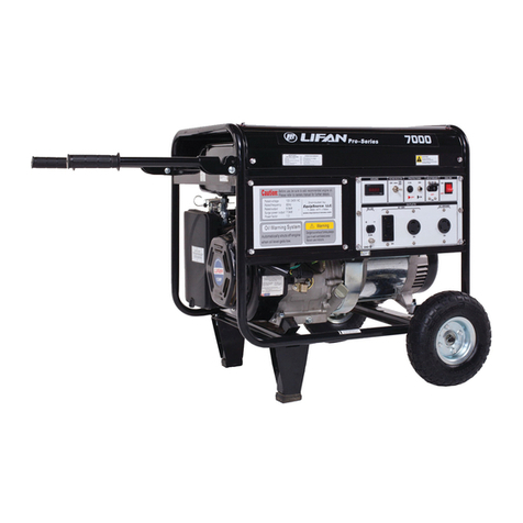
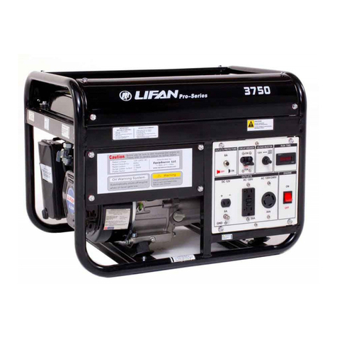
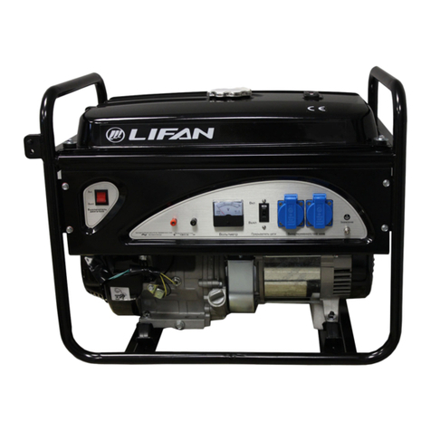
Lifan G1800 User manual

ll
,ll[h llFîlR{Èr '
,J.fR I
IlI
tII
LIEIIN Ir lllt Êl{llliùT{ili*
CHONGQING LIFAN POWER CO.,LTD.
LIFAN GENERATOR MANUAL
G1800(1800W)

PREFACE
Thank you for choosing a gasoline generator set by our Co., ::
Based on the latest technology at home and abroad, our Co., has successfully developed the
gasoline generator set. The unit is cltaructerized by advanced design, cornpact structure, reliable per-
formance, low noise and small vibration. With general gasoline engine 160F as power, it is widely
used in many fields such as living, open working, shop, fishing, etc"
The manual gives information with respect to operation and maintenance of the gasoline genera-
tor, and be sure to read it carefully first before operation. If any trouble occurs, call your dealer whô
will provide you with the best after service.
All the materials and diagrams of this manual are in accordance in this manual may be a iittle
different from the actual starus. The copyright of this manual belongs to our Co., any group or indi-
vidual is forbidden to reprint or copy any it. The manual is subject to change without notice.
I
TMPORTANT NOTICES
Please pay special attention to statements preceded by the following words:
AWARNING --:
O A warning is used to alert the user to fact thathazardous operation and maintenance procedures may
result in injury to or death ofpersonnel ifnot strictly observed.
CAUTION
O A caution is used to alert the user to fact that hazardous operation and maintenance procedures may
result in injury to or death ofpersonnel if not strictly observed.i
NOTE
O Give helpful information.
This manual should be considered as a permanent part of the unit and should remain with the unit when
resold.
t

CONTEI{TS
1" Generator Safety
2.Introduction to parts and components........ ..................5
::
3. Pre-Operating Inspection .......".....6
4. Starting the Engine ..!.d...................................9
5. Generator use 13
6. Stopping the 8ngine............. ........17
7. Maintenance......... ................. .....18
8. Transporting and Storage.... ."....23
9. Troubleshooting... ....."..25
10. Electricity principle diagram.............. .......27
11. Specifications .".........28
3

1. GENERATOR SAFETY
To ensure safe operation-
l. Place the generator at least 1m away from building or other equipment when operating the generator.
2. Operate the generator on a level surface. If the generator is tilted, fuel spillage away result.
3. Exhause gas contains poisonous carbon monoxide. Never run the generâtor in an enclosed area. Be sure to pro-
vide adequate ventilaton.
4. Know how to stop the generator quickly and understand operation of all the controls. Never permit any one to
operate the generator without proper instructions.
5. Keep children and pets away from the generator when it is in operation.
6. Keep away from rotating parts while the generator is running.
7. The generator is a potential source of electrical shocks when misued, do not operate with wet hands.
8. Do not operate the generator in rain or snow and do not let it get wet.
4

2. INTROUCITON TO PARTS AND COMPONENTS
Hanging r1ng Fuel filler cap
Carburetor
choke lever Engine switch Spark plug
Ac current
Protector
Air cl Dc plug et
Dipstick uffler
Starter eEarth terminal QnnLof
5
a
a
a
3
a
o.=
-
cf
cf :
Go
-f
-t

3. PRE-OPERATION INSPECTION
3.1 Engine oil
CAUTION
O Engine oil is a key factor in deciding the engine's performance. Do not apply engine oil with additives
or 2-stroke gasoline engine oil, as they haven't enough lubrication, whicti-inay shorten the engine's service life.
O Check the engine with it stopped on a level ground.
SAEI0W-30 is recommended for general, all temperature use.
SAE
Temperature trlrllll
-30 -20 -t0 0 10 20 30 40"c
Fnvironmcnl tcmncraf r rrc
As viscosity varies with regione and temperatures, so the lubricant has to be selected in accordance with
our recommendation. If single viscosity engine oil is to be used instead, its viscosity corresponding to average
temperature of the region must be considered.
6
3I
-30

%% Oil level
I
Check Ensure that the engine is stopped on a level ground.
(1) Remove the dipstick and clean it.
(2) Reinsert the dipstick into the oil filler without screwing in, and check oil level.
(3) If the oil level is too low, add the recommended engine oil to the oil filler neck.
(4) Reinstall the dipstick
CAUTION
O Run with insufficient engine oil may damage severely.
3.2 Air cleaner
Check the filter element for dirt, and remove it if any.
CAUTION
O Never run the engine without an air cleaner, or severe wear of the engine may occur.
3.3 Fueland Fuel tank
3.3.1 Fuel
7

The engine must apply unleaded gasoline or low-leaded gasoline. Using unleaded gasoline will decrease
the possibility of producing carbon deposit and prolong the engine's service life.
Never use an oil/gasoline mixture or dirry gasoline. Avoid getting dirt, dust or water in the fuel tank.
3.3.2 Fuel Tank
Fuel tank capacity: 7.5 liters ::
AWARNING
O Gasoline is extremely flammable and is explosive under certain conditions.
O Refueling in a well-ventilation area with the engine stopped. Do not smoke and allow flames or
sparks in the area where gasoline is stored or where the fuel tank is refueled.
O Do not overfill the tank (there should be no fuel in the filler neck). After refueling, make sure the fuel
tank cap is set back securely.
O Be careful not to spill fuel when refueling. Spilled fuel or fuel vapor may ignite.
O If petrol is spilled, do not attempt to start the engine but move the machine away from the area igni-
tion until petrol vapour have dissipated.
O Avoid repeated or prolonged contact with skin or breathing of fuel vapor.
O Keep out of reach of children.

4. STARTING THE ENGINE
CONTROLS-
O Engine switch: To start and stop the engine
O Switch positions:
OFF: To stop the engine :-:
ON: To start and run the engine
O Recoil starter:
To start the engine, pull the starter grip lightly until resistance is felt, then pull briskly
NOTE: Do not allow the starter grip to snap back against the engine. Return it gently to prevent damage to
the starter.
O Choke rod:
The choke rod opens and closes the choke valve in the cal'buretor. Pulling the choke rod to the
CLOSED position enrich the fuel mixture for starting a cold engine.
Pushing the choke rod to the OPEN position provides the correct fuel mixture for operation after
starting ,and for restarting a warm engine.
O AC circuit breaker:
The AC circuit breaker will automatically switch OFF if there is a short circuit or an overload of the generator
at the AC receptacle. If the AC circuit breaker is switched off automatically, check that appliance is working properly
and does not exceed the real load capacity of the AC circuit before switching the AC circuit breaker ON again.
9

The AC circuit breaker may be used to switch the generatorAC power ON or OFF.
O AC Circuit protector:
The AC circuit protector will automatically shut off the AC output power if there is a short circuit or an over-
load ofthe generator at the generator receptacle. ::
The red indicator inside the clear circuit protector has switch off. Wait a few minutes and push the button in to
reset the circuit protector, and then restart the engine.
If the circuit protector is switched off check that the appliance is working properly and does not exceed the
rated load capacity of the circuit before switch the circuit protector ON again.
l0

4.1 Remove all loads fromAC socket.
4.2Turn engine switch to "ON". switch
0ll
f
!Ër ô
ç:
E:P
{5.
ë:
ct
È-
NOTE
O Do not use the choke when the engine is warm or the air temperature is high.
4.3 Push the choke lever to the OFF position.
Choke level
OFF
3c
ll

4.4 putt slowly on recoil starter until engaged, then pull it briskly
Lî
(ô)
NOTE
O Do not allow the starter grip to snap back. Return it slowly by hand.
4.5 Gradually move the choke lever to the ON position. Warm up the engine until it runs smoothly
Choke level
OFF o
"a
12

5" GENEKA*TOR USE
Always do as following described to keep the generator in a sound condition.
A wARNING
5.1 Always connect the generator to the earth to prevent misusing. The generator ground
terminal is connected to the frame of the generator, the metallon-current-carrying parts of the
generator, and the ground terminal of each receptacle
5.2 The user shall integrate the generator with an earth fault supervise system to know that there
is a fault and to track it and eliminate it promptly before a second fault occurs.
I
to
t\
aa
13

5.3 The following table gives reference information to connect the electric appliances to generator
Description 'Wattage Typifier Example
Start Rating Elgctric device Start Rating
Olncandescet lamp
OHeating device Xxl &Incandescent lamp
ffi
TV
Incandescen! lamp
#
l00w lOOVA
(vi) IOOVA
(w)
OFluorescent lamp x) x 1.5
Fluorescent lamp
@Fluorescent lamp
@ 4ow SOVA
(w) 6OVA
(w)
OMotor drive
device x3 -5 x)
Refrigerator
g
Electric fan
Refrigerator
150W
450-75OVA
(w) 3OOVA
(w)
t4

5.4 If the generator is to supply two or more loads with power, be sure to connect them one by
one. The one with the higher start current first.
1
Irr
\
so2I
3
15

AWARNING
O When connect the generator to home power supply, be sure that a skilled electrician does this job. Im-
proper connecting between the generator and loads may cause damage to the generator, even a fire.
AC application
O Start the engine and make sure the pilot lamp comes on. trf not, the filament may be burnt out.
O Switch on the AC circuit breaker.
NOTE:
O The breaker will automatically switch off when the circuit is short-circuited.
O Plug in the appliance, use three-pronged plugs.
NOTICE:
When operators, maintenance men use or maintain it, please do as the follows to avoid damages to the
human body:
O Please put on the earphones due to the noise from the exhaust system.
g Please put on the overall and gloves as there is a hot component.
When connect or test the electronics, please put on the insulative shoes and gloves in case the electric
shock caused by the touch to the electriferous.
16

6. STOPPING THE ENGINE switch
6.1 Tum the engine switch OFF
6.2Tum the choke lever ON
NOTICEI To stop the engine in an emergency, turn the engine switch OFF"
oI
r
{trr
t7

7. MAINTENANCE SCHEDULE
Periodic inspection and adjustment of the essential if high level performance is to be maintained. Regular
maintenance will also ensure a long service life. The required service intervals and the kind of maintenance to be
performed are described on the table below. Maintenance Schedule i
CAUTION
Use only genuine parts manufactured by the company or equivalents in quality; otherwise damage to
equipment may occur.
18
PERIO Each time Initial l month
nr ?ô llrs Initial3 month
nr 5O Hrs F.very 6 month
or .l 00 Hrs Every 1 years
or 300 Hrs
Engine oil Check oil level A
Replace AA
Air cleaner Check A
Replace-clean AO
Deposit cup Clean AC A
Spark plug Check-clean A
Replace A
Valve clearance Check-adiust A(D
Combustion chambel Check-adiust A€)
Fuel tank and
Fuel fitter Clean A@
Fuel suoolv line Clean Every two years (do a replacement'if necessary) @

NOTES
O The item should be serviced more often than that in the schedule if used in dusty circumstances.
O The item should be done by your dealer unless you are specially trained is well equipped with tools.
O The installation and major repair work shall be carried out by speci{ically trained personnel.
7.1 Replacement of engine oil ::
A still hot engine is helpful to drain out the engine oil in the crankcase rapidly and entirely.
7.1.1 Turn off the oil filler cap and drain plug to drain engine oil thoroughly.
7.1.2 Reinstall the drain plug and screw in securely.
7.1"3 Fill the specified engine, and check the oil level.
7. I "4 Reinstall the oil filler cap.
Engine oil capacity: 0.35L "
CAUTION
Do not contact engine oil repeatedly for long-time, it may cause skin cancer. Wash your hands with soap
and water immediately after handling oil"
NOTE
Do not dump oil containers or discarded engine oil into rubbish boxes or onto the ground. f,'or the sake
of environmental protection, we suggest you take in discarded engine oil with a closed container and bring to
local recycling station.
Service of air cleaner
A dirty air cleaner may block enough air's flowing into the carburetor. To prevent the carburetor
from producing of trouble, please service the air cleaner periodically. If operating the engine in ex-
tremely dusty area, the job should be done more often.
19
Table of contents
Languages:
Other Lifan Portable Generator manuals

Lifan
Lifan G12500E User manual

Lifan
Lifan KP2300i-2 User manual

Lifan
Lifan G2300i User manual

Lifan
Lifan PRO Series Assembly instructions

Lifan
Lifan 2.8GF-3/4 User manual

Lifan
Lifan ES1500 Assembly instructions

Lifan
Lifan ESI3600iER Assembly instructions

Lifan
Lifan 7000 Pro series User manual

Lifan
Lifan LF3750 Assembly instructions

Lifan
Lifan KP4500iE User manual