Life form CRiSis LF03953U User manual

Products by Nasco
CRiSis
™™
Manikins
LF03953U – Complete CRiSis™
LF03955U – Deluxe CRiSis™
LF03956U – Deluxe Plus CRiSis™
LF03965U – CRiSis™ Auscultation
LF03966U – CRiSis™ Auscultation w/Interactive ECG
LF03968U – Deluxe Plus CRiSis™ Auscultation
INSTRUCTION MANUAL
NOTE: These products contain dry natural rubber.

Table of Contents . . . . . . . . . . . . . . . . . . . . . . . . . . . . . . . . . page
Introduction .................................................. 4
Identifying Your Model. . . . . . . . . . . . . . . . . . . . . . . . . . . . . . . . . . . . . . . . 5-10
Procedure A: Setting Up Your Simulator
Airway Management Head
Introduction . . . . . . . . . . . . . . . . . . . . . . . . . . . . . . . . . . . . . . . . . . . . . . 11
Set-Up . . . . . . . . . . . . . . . . . . . . . . . . . . . . . . . . . . . . . . . . . . . . . . . . 11-12
Cleaning & Maintenance ..................................12-13
Using the Combitube®. . . . . . . . . . . . . . . . . . . . . . . . . . . . . . . . . . . . . . 13
Supplies/Replacement Parts for Airway Management Trainer ........ 13
Injectable Training Arm
Introduction . . . . . . . . . . . . . . . . . . . . . . . . . . . . . . . . . . . . . . . . . . . . . . 14
Internal Structure. . . . . . . . . . . . . . . . . . . . . . . . . . . . . . . . . . . . . . . . . . 14
Set-Up . . . . . . . . . . . . . . . . . . . . . . . . . . . . . . . . . . . . . . . . . . . . . . . . 14-16
Troubleshooting. . . . . . . . . . . . . . . . . . . . . . . . . . . . . . . . . . . . . . . . . 16-17
Cleaning & Maintenance .................................... 17
Cautions ................................................ 17
Supplies/Replacement Parts for Injectable Training Arm ............ 17
Blood Pressure Simulator
Introduction . . . . . . . . . . . . . . . . . . . . . . . . . . . . . . . . . . . . . . . . . . . . . . 18
Set-Up . . . . . . . . . . . . . . . . . . . . . . . . . . . . . . . . . . . . . . . . . . . . . . . . . . 18
Control Panel. . . . . . . . . . . . . . . . . . . . . . . . . . . . . . . . . . . . . . . . . . . . . 19
Pulse Feature ..........................................19-20
Using the Blood Pressure Simulator .........................20-21
Low Battery . . . . . . . . . . . . . . . . . . . . . . . . . . . . . . . . . . . . . . . . . . . . . . 21
Limited Warranty
Nasco warrants to the purchasers of
CRiSis™
manikin products that they will
be free from defects in material and workmanship for a period of three years
from the date of purchase. Nasco will repair any defect reported within three
years of the date of purchase at no charge. Products found to be defective
may be returned to the authorized Nasco dealer from whom the item was
purchased, or returned directly to Nasco. Nasco will be liable under this lim-
ited warranty only if
CRiSis™
manikin products have been serviced properly
as directed in the operating manual.
Nasco will not be responsible for damage caused by unauthorized repairs or
modifications that have been made, or if the product has been damaged
through misuse, accident, or abuse. This warranty does not cover wear and
tear or expendables such as batteries, lubricant, and replacement lungs.
There are no other expressed or implied warranties of merchantability, fitness of
purpose, or otherwise on
CRiSis™
manikin products, parts, and accessories.

3
TableofContentscont.............................page
Calibration Procedures ..................................... 21
Using Your Own Equipment ................................. 22
Supplies/Replacement Parts for Blood Pressure Simulator. . . . . . . . . . 22
Defibrillation Chest Skin
Introduction . . . . . . . . . . . . . . . . . . . . . . . . . . . . . . . . . . . . . . . . . . . . . . 23
Connecting Your Arrhythmia Patient Simulator .................23-24
Troubleshooting. . . . . . . . . . . . . . . . . . . . . . . . . . . . . . . . . . . . . . . . . . . 24
Supplies/Replacement Parts for Defibrillation Chest Skin ........... 24
Procedure B: Interactive ECG Simulator
Introduction . . . . . . . . . . . . . . . . . . . . . . . . . . . . . . . . . . . . . . . . . . . . . . 25
Getting Started ........................................... 26
Defibrillation Training — Adult ................................ 27
External Pacer Training — Adult .............................. 27
Defibrillation Training — Pediatric ............................. 28
External Pacer Training — Pediatric ........................... 28
Procedure C: Auscultation
Introduction . . . . . . . . . . . . . . . . . . . . . . . . . . . . . . . . . . . . . . . . . . . . . . 29
Instructions for Use ........................................ 29
Supplies/Replacement Parts for Auscultation .................... 29
Introduction to External Monitors ................................ 30
Procedure D: Light Controller Set-Up
Introduction — Light Controller . . . . . . . . . . . . . . . . . . . . . . . . . . . . . . . 30
Set-Up . . . . . . . . . . . . . . . . . . . . . . . . . . . . . . . . . . . . . . . . . . . . . . . . . . 30
Operation .............................................30-31
Troubleshooting. . . . . . . . . . . . . . . . . . . . . . . . . . . . . . . . . . . . . . . . . . . 31
Procedure E: Memory Unit Set-Up
Introduction — Memory Unit . . . . . . . . . . . . . . . . . . . . . . . . . . . . . . . . . 31
Set-Up . . . . . . . . . . . . . . . . . . . . . . . . . . . . . . . . . . . . . . . . . . . . . . . . 31-32
Operation ............................................... 32
Practice Modes ........................................... 32
Test Modes .............................................. 33
Troubleshooting. . . . . . . . . . . . . . . . . . . . . . . . . . . . . . . . . . . . . . . . . . . 33
Procedure F: Printer Set-Up
Introduction — Printer . . . . . . . . . . . . . . . . . . . . . . . . . . . . . . . . . . . . . . 34
Set-Up . . . . . . . . . . . . . . . . . . . . . . . . . . . . . . . . . . . . . . . . . . . . . . . . . . 34
Waveform Printout . . . . . . . . . . . . . . . . . . . . . . . . . . . . . . . . . . . . . . . . . 34
Paper Installation. . . . . . . . . . . . . . . . . . . . . . . . . . . . . . . . . . . . . . . . . . 35
Troubleshooting. . . . . . . . . . . . . . . . . . . . . . . . . . . . . . . . . . . . . . . . . 31-33
Supplies/Replacement Parts for Printer . . . . . . . . . . . . . . . . . . . . . . . . . 36

4
*Resusci®Anne™ is a trademark of Laerdal Medical Corporation.
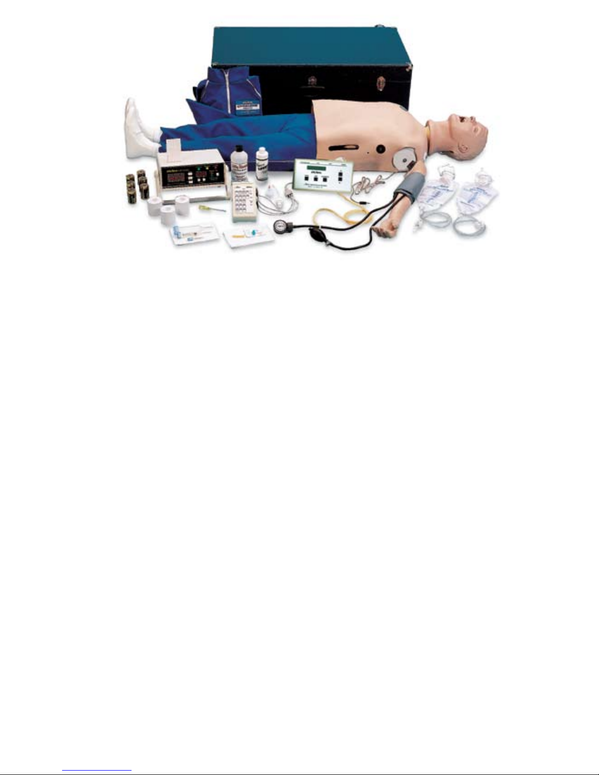
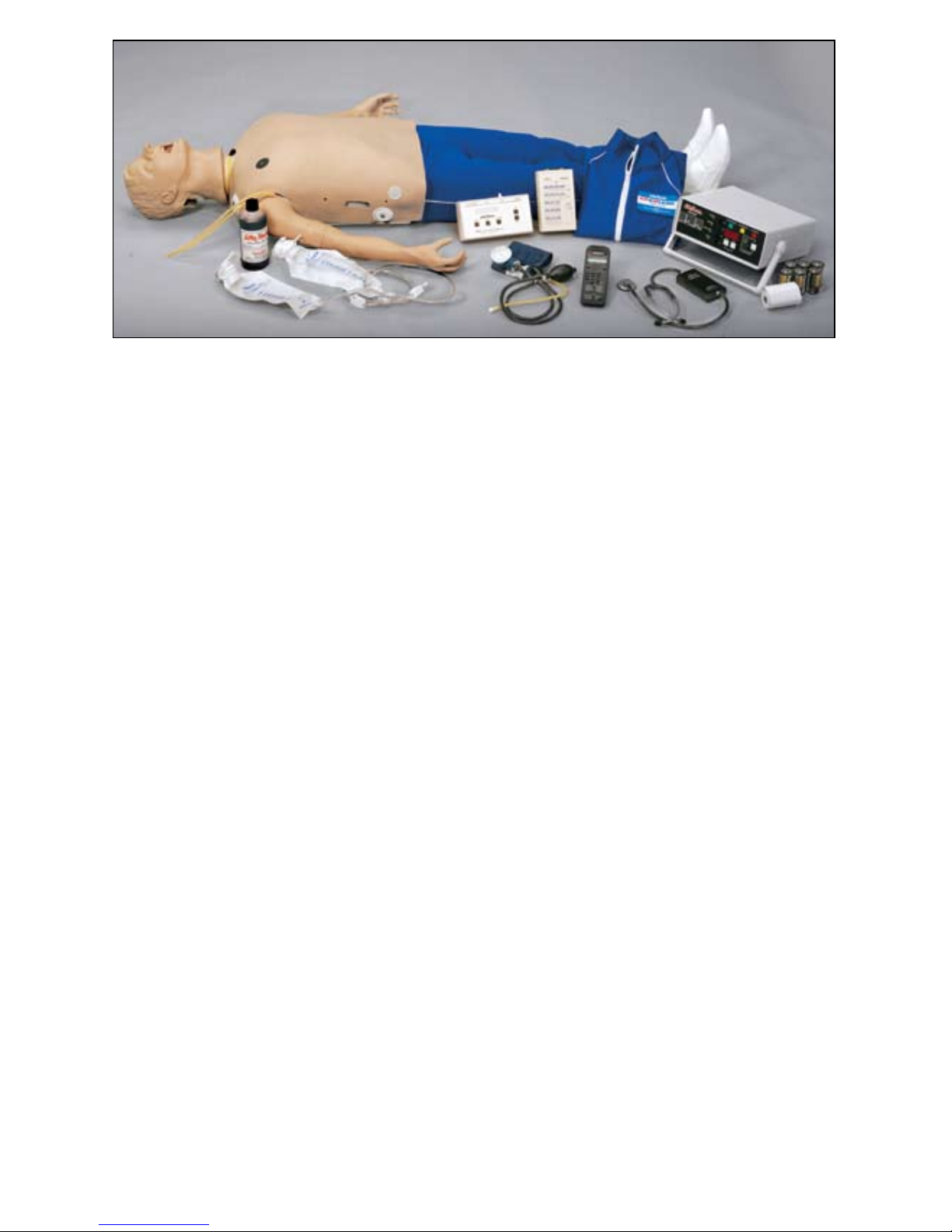
All of the Adult CRiSis™ Manikins
are Complete Resuscitation Systems
with five stations allowing you to
practice different scenarios. Each
manikin consists of a full body CPR
manikin, IV Arm, Blood Pressure Arm,
Defibrillation Chest Skin, and features
the Airway Larry Airway Management
Head. Ideal for ACLS, paramedic,
EMT, and nursing training at every
level. Modular components allow
you to create a manikin to suit your
needs.
This manual will guide you in set-
ting up, using, and maintaining each
of the available components. Each
section also includes a list of replace-
ment parts, supplies, and auxiliary
equipment.
By reading and following all instruc-
tions carefully and completely, you
can be sure your
Life/form®
CRiSis™
Manikin will provide years of valuable
service.
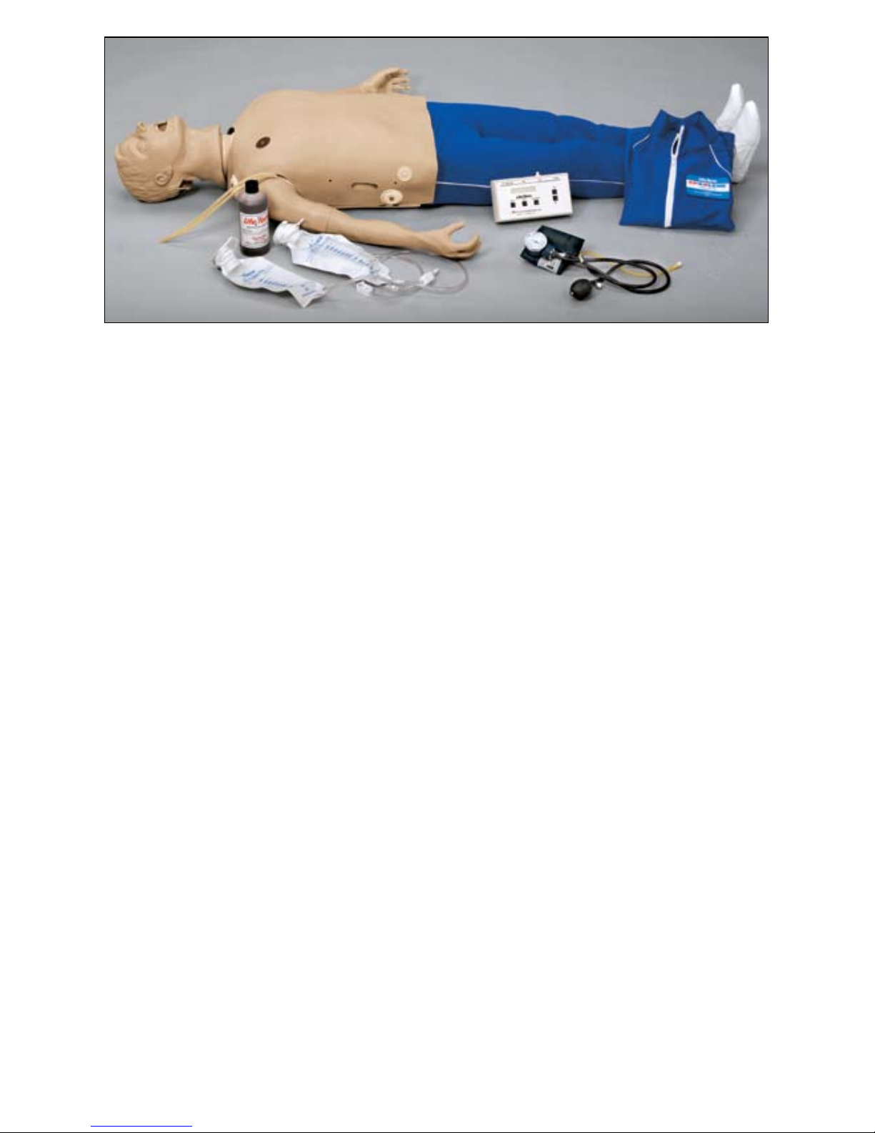
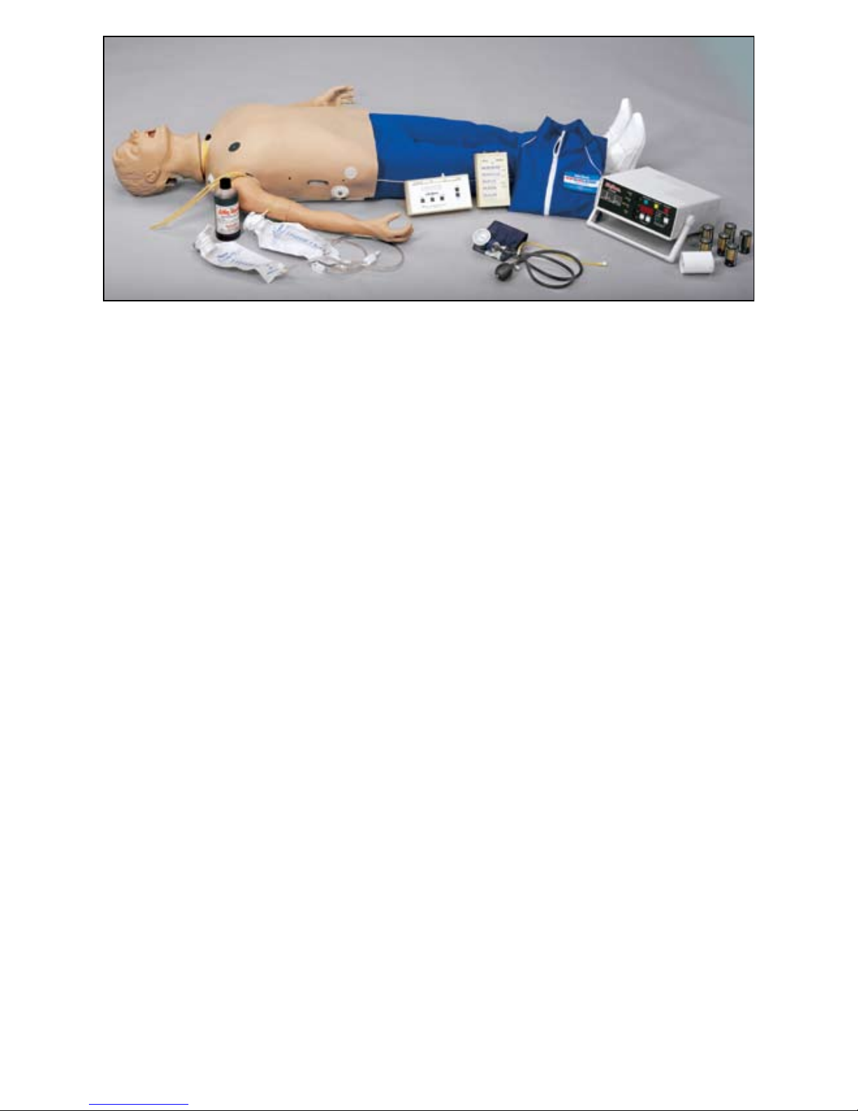
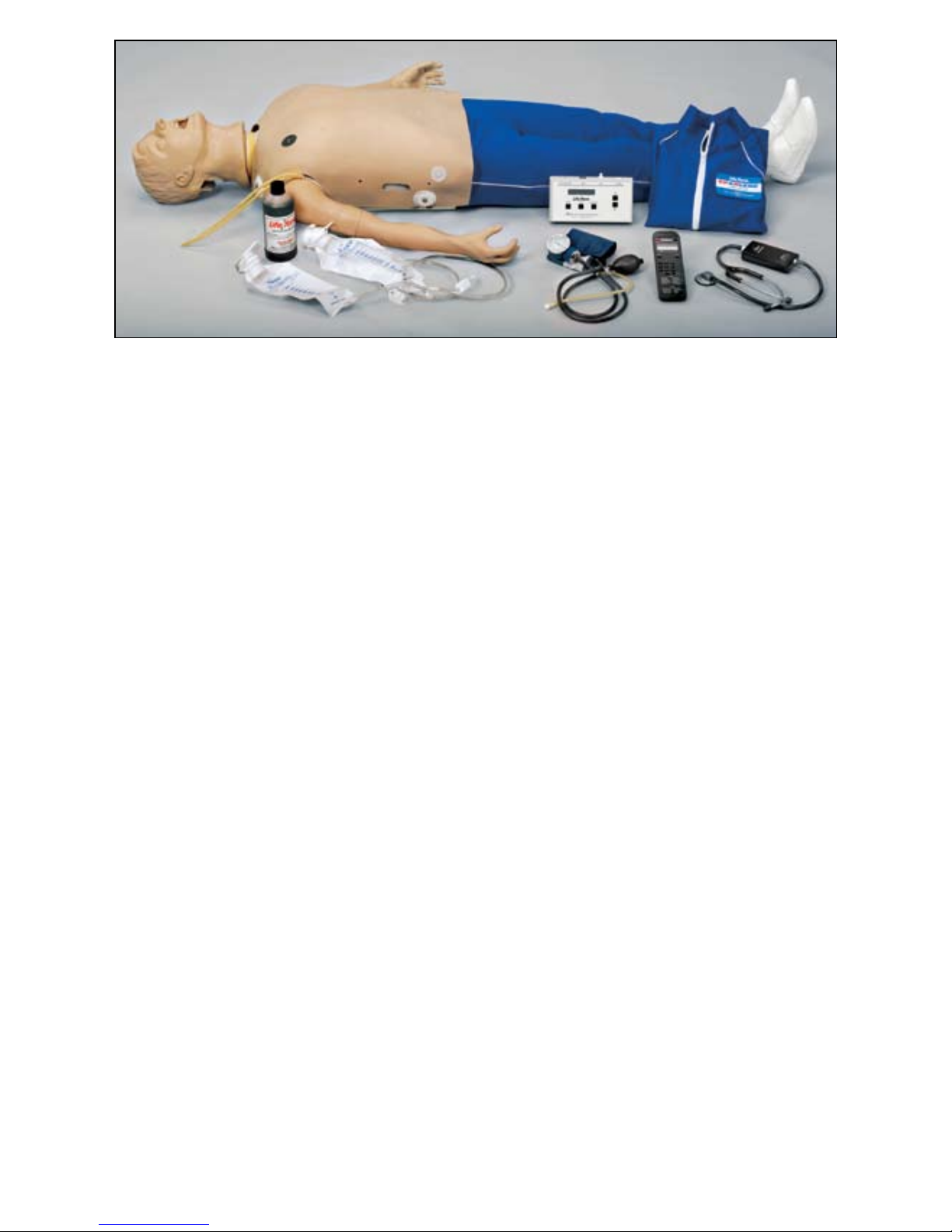
IDENTIFYING YOUR MODEL
Pages 5-10 display the Adult CRiSis™
family of simulators. Identify your
Life/form®Adult CRiSis™Manikins
model and refer to the Operation
Section pertaining to your model.
This guide has been carefully written
to guide you in the operation of your
unit. Depending on your model, please
read the procedure(s) indicated. All
models follow procedure A. Check
your model description to see if proce-
dures B, C, D, E, or F pertain to your
model
Cleaning:
Normal surface soil can be removed
from the trainer with mild soapy water.
Do not allow water to contact electri-
cal components. Stubborn stains
may be removed with REN Cleaner
(W09919U). Simply apply the REN
Cleaner to the soiled area and wipe
clean with a soft cloth.
NOTE: Avoid using cleaner around the
mouth area if students will be apply-
ing direct mouth-to-mouth resuscita-
tion techniques, as the cleaner may
be toxic if ingested. NEVER place the
trainer on any kind of printed paper
or plastic. These materials, as well as
ballpoint pens, will transfer indelible
stains. Do not use any cosmetics.

5
Complete CRiSis™Manikin — LF03953U
LIST OF COMPONENTS:
•CRiSis™ manikin, Full Body Manikin with “Airway Larry”
Management Head
•IV Arm
•Blood Pressure Arm
•Electronic Blood Pressure Control Unit
•Defibrillation Chest Skin
•Pump Spray Lubricant
•3 cc Syringe with Needle
•12 cc Syringe with Needle
•Two IV Bags
•Three Pinch Clamps
•Two Small Towels
•Butterfly Infusion Set
•Synthetic Blood
•Sphygmomanometer
•Batteries Included
•No Electronic Connections
Follow Procedure A

6
Deluxe CRiSis™Manikin — LF03955U
LIST OF COMPONENTS:
•CRiSis™ manikin, Full Body Manikin with “Airway Larry”
Management Head
•IV Arm
•Blood Pressure Arm
•Electronic Blood Pressure Control Unit
•Defibrillation Chest Skin
•Pump Spray Lubricant
•3 cc Syringe with Needle
•12 cc Syringe with Needle
•Two IV Bags
•Three Pinch Clamps
•Two Small Towels
•Butterfly Infusion Set
•Synthetic Blood
•Sphygmomanometer
•Batteries Included
•No Electronic Connections
•Interactive ECG Simulator
Follow Procedure A & B

7
Deluxe Plus CRiSis™Manikin — LF03956U
LIST OF COMPONENTS:
•CRiSis™ manikin, Full Body Manikin with “Airway Larry”
Management Head
•IV Arm
•Blood Pressure Arm
•Electronic Blood Pressure Control Unit
•Defibrillation Chest Skin
•Pump Spray Lubricant
•3 cc Syringe with Needle
•12 cc Syringe with Needle
•Two IV Bags
•Three Pinch Clamps
•Two Small Towels
•Butterfly Infusion Set
•Synthetic Blood
•Sphygmomanometer
•Batteries Included
•No Electronic Connections
•Interactive ECG Simulator
•Electronic Memory Unit with Printer
•Three Rolls of Thermal Recording Paper
•Hard Storage Case with Wheels
Follow Procedure A, B, D, E, & F

8
CRiSis™Auscultation Manikin — LF03965U
LIST OF COMPONENTS:
•CRiSis™ manikin, Full Body Manikin with “Airway Larry”
Management Head
•IV Arm
•Blood Pressure Arm
•Electronic Blood Pressure Control Unit
•Defibrillation Chest Skin
•Pump Spray Lubricant
•3 cc Syringe with Needle
•12 cc Syringe with Needle
•Two IV Bags
•Three Pinch Clamps
•Two Small Towels
•Butterfly Infusion Set
•Synthetic Blood
•Sphygmomanometer
•Batteries Included
•No Electronic Connections
•Auscultation Chest
•Auscultation Remote Control with SmartScope™
•Hard Storage Case with Wheels
Follow Procedure A & C

9
CRiSis™Auscultation Manikin with Interactive ECG
Simulator — LF03966U
LIST OF COMPONENTS:
•CRiSis™ manikin, Full Body Manikin with “Airway Larry”
Management Head
•IV Arm
•Blood Pressure Arm
•Electronic Blood Pressure Control Unit
•Defibrillation Chest Skin
•Pump Spray Lubricant
•3 cc Syringe with Needle
•12 cc Syringe with Needle
•Two IV Bags
•Three Pinch Clamps
•Two Small Towels
•Butterfly Infusion Set
•Synthetic Blood
•Sphygmomanometer
•Batteries Included
•No Electronic Connections
•Auscultation Chest
•Auscultation Remote Control with SmartScope™
•Interactive ECG Simulator
•Hard Storage Case with Wheels
Follow Procedure A, B, & C

10
Deluxe Plus CRiSis™Auscultation Manikin — LF03968U
LIST OF COMPONENTS:
•CRiSis™ manikin, Full Body Manikin with “Airway Larry”
Management Head
•IV Arm
•Blood Pressure Arm
•Electronic Blood Pressure Control Unit
•Defibrillation Chest Skin
•Pump Spray Lubricant
•3 cc Syringe with Needle
•12 cc Syringe with Needle
•Two IV Bags
•Three Pinch Clamps
•Two Small Towels
•Butterfly Infusion Set
•Synthetic Blood
•Sphygmomanometer
•Batteries Included
•Electronic Connections
•Auscultation Chest
•Auscultation Remote Control with SmartScope™
•Interactive ECG Simulator
•Electronic Memory Unit with Printer
•Three Rolls of Thermal Recording Paper
•Hard Storage Case with Wheels
Follow Procedure A, B, C, D, E, & F

11
Nasco Life/form® “Airway Larry”
Airway Management Head
About the Simulator…
The
Life/form®
“Airway Larry” Airway
Management Trainer is the most
realistic simulator available for the
training of intubation and other airway
management skills.
Nasco has taken great care to cre-
ate an airway management trainer
that is anatomically correct in respect
to both size and detail. Landmarks
include: nostrils, teeth, tongue, oral
and nasal pharynx, larynx, cricoid
ring, epiglottis, arytenoid, false and
true cords, trachea, esophagus,
“Airway Larry” lung set, and stomach.
Nasco’s “Airway Larry” allows you
to practice oral, digital, and nasal
intubation. E.T., E.O.A., PTL®, and
Combitube®insertion can all be prac-
ticed as well (please see “Using the
Combitube®”). Suction techniques and
proper cuff inflation can also be per-
formed and evaluated.
Lubricating the Airway Trainer Head:
Lubricate both the simulator and
supplies being used with the Nasco
pump spray lubricant provided. (See
figures 1 & 2.)
Figure 1
Figure 2
NOTE: Nasco recommends the use
of the provided lubricant or a similar
vegetable-based lubricant for the
Airway Management Trainer head.
The use of a silicone-based lubricant
may cause damage to the simulator,
thus voiding Nasco’s warranty on the
trainer.
Set Up:
A. Connecting the Airway
1. The manikin’s airway has been
disconnected to prevent damage
during shipping. To connect the
airway, remove the chest skin,
chest plate, compression springs,
and upper compression plate.
NOTE: Caution must be taken not to
damage the defibrillation electron-
ics attached to the chest skin when
removing the skin from the manikin.
Procedure A

12
Figure 3
2. Remove the lung bags from
the upper compression plate.
Connect the right and left lung
bags to the adapters in the right
and left bronchi. (See figure 3.)
B. Installing the Chest
Compression Plate
1. Remove the compression springs
from packaging. Insert the springs
into the four plastic cylinders
extending up from the lower com-
pression plate. (See figure 4.)
2. Before replacing the upper com-
pression plate, make sure the
lung bags are connected to the
tracheal tube extending from the
lower portion of the neck of the
Airway Management Trainer head.
Figure 4
3. Position the upper compression
plate over the springs so that
each of the springs fits up into
a cylinder on the bottom of the
upper compression plate. (See
figure 5.)
Figure 5
4. Place the lung bags through the
hole in the center of the upper
compression plate so they rest on
top of the plate. (See figure 6.)
Figure 6
5. Place the chest plate back over
the upper compression plate and
lungs.
6. Reattach the chest skin by adjust-
ing the Velcro®edges. Again, be
careful not to damage the elec-
tronics attached to the chest skin.
Cleaning & Maintenance:
To clean the Airway Management
Trainer head, you will need to remove
the head from the manikin. To do so,
disconnect the lungs from the bronchi.
Then, rotate the head so that it is fac-
ing backwards. The large tab on the
front of the neck should be aligned with
the keyway in the torso. Tilt the head
upward until it snaps free. Disengage
the smaller rear tabs from the neck
opening and pull the head from the
body. (See figure 7.) Reverse these
steps to reattach the head.
Procedure A

13
Figure 7
Next, take the trainer to an area with a
sink and open counter space. Using
the red caps supplied, plug off the
right bronchus (the esophagus should
already be plugged). Stabilize the
head on the counter face-up (towels
work well for this) with plugged tubes
hanging over the sink. (See figure
8.) Carefully pour warm soapy water
(a mild dish soap works best) into the
mouth until the water level reaches
halfway up the tongue. Tilt the head
back and bring the neck up 3" off the
countertop.
Figure 8
Continue filling until the water level
covers the tongue. At this point, take
a small soft brush and gently scrub
the inside of the mouth (a small tooth-
brush works well for this). Cotton
swabs can be used to scrub inside the
nostrils. When done, pull the plug from
the esophagus and drain the water
into the sink. Now pick the head up to
a vertical position and pull the plugs
from the trachea to completely empty
the system. (See figure 9.)
Rinsing the Airway:
To rinse the airway, follow the same
procedure using clean, warm tap water.
Repeat this process until all the soap
has been flushed from the system.
Figure 9
Disinfecting the Airway:
To disinfect, repeat the standard
cleaning procedure, but this time use
a bleach solution, as specified by the
Centers for Disease Control, instead
of soapy water. Fill the system with
the solution until it reaches the cor-
ners of the mouth. Remember to start
filling with the head flat and finish with
the neck slightly elevated to ensure
that the solution completely fills all
airway passages. Once completely
filled with the bleach solution, allow
the head to sit for at least 10 minutes.
Drain as described earlier and repeat
the rinsing process to flush out all
of the bleach solution. Set the head
aside and allow it to dry completely.
Using the Combitube®:
Thoroughly read and follow the instruc-
tions that come with the Combitube®.
The trainer will accept either a full-size
or a small adult tube. As with a live
patient, it may be necessary to back
the tube out slightly if ventilation can-
not be established.
NOTE: Depending on tube placement,
the large cuff may not accept the rec-
ommended amount of air. In this case,
simply inflate the cuff to its maximum
volume (when the plunger stops) and,
while holding the plunger down, detach
the syringe from the blue pilot balloon,
and proceed.
Supplies/Replacement Parts for
Airway Management Trainer Head:
LF03285U Replacement Lungs
LF03644U Nasco Pump Spray
Lubricant
W09919U REN Cleaner
Procedure A

14
Figure 10
Nasco
Life/form®
Injectable
Training Arm
About the Simulator…
The
Life/form®
Injectable Training Arm
Simulator duplicates the human con-
dition as closely as modern plastics
technology allows — it is almost the
real thing. (See figure 10.) Its care
and treatment should be the same
as with a patient; abuse or rough
handling will damage the simulator
— just as it would cause pain to a
patient.
Although this arm will provide years
of trouble-free usage, the skin and
veins can be readily replaced when
needed. The outer skin is easily
peeled off revealing the “core” and
veins, providing, literally, a brand new
arm. The life of the replaceable skin
and veins will be prolonged by utiliz-
ing smaller needle sizes (such as 20-
to 25-gauge). However, if instruction
with larger needle sizes is required,
this can be done; the skin and veins
will merely need to be replaced
sooner. The Skin and Vein Kits are
available through Nasco (see page 9
for list of supplies).
Internal Structure:
Internally, the vascular structure (rub-
ber tubing) begins at the shoulder and
continues under the arm, crosses the
antecubital fossa forearm, makes a
loop in the back of the hand, and then
returns to the underarm. This venous
system is constructed of special plastic
Figure 11
tubing with the lumen being the
approximate size of a human vein.
(See figure 11.) This vascular struc-
ture has an inlet tubing and an outlet
tubing at the shoulder. It is via these
tubes that synthetic blood is injected
and removed, thus allowing practice
in the techniques of blood drawing
and starting intravenous infusions.
Set-Up:
A. Preparing the Synthetic Blood
1. Fill the pint bottle containing syn-
thetic blood concentrate with dis-
tilled water. (See figure 12.)
2. Pour the synthetic blood into one
of the bags. (See figure 13.)
Figure 12
Pinch
Clamp
Outlet Tubing
Inlet Tubing
Pinch
Clamp
12"
Life/form®
Blood
Venous System
Anterior Posterior
Needle
Adapter
Posterior Anterior
Procedure A

15
Figure 13
3. Be sure the clamp on the IV tub-
ing is closed, and hang the bag
no more than 18" above the level
of the arm.
4. Attach the end of the IV tubing to
one of the shoulder tubings.
5. With the other shoulder tubing in
a basin or sink, gradually “flush”
the vascular system with syn-
thetic blood by slowly opening
the clamp. Allow some “blood” to
pass through the system until the
air bubbles have been eliminated.
6. Once the system is filled, use one
of the pinch clamps to close off the
blood outlet tubing. The venous
system is now full of “blood” and
pressurized. Be sure to leave the
clamp on the IV tubing open.
7. After filling the venous system
according to instructions, the
arm is now ready for you to
practice drawing blood. Blood
can be drawn anywhere along
the pathway of the vein. Distilled
water, rather than alcohol, should
be used to prepare the sites.
Synthetic blood will actually be
aspirated once the vein is prop-
erly punctured.
8. Small diameter needles (20- to
25-gauge) should be used.
Figure 14
B. Preparing the Arm for
Intravenous Infusions
1. Close the clamp at the end of IV
bag A tube, then fill with water
(distilled water is recommended),
and hang not more than 18"
above the arm. (See figure 14.)
2. Appropriate intravenous infusion
needles (or butterflies) should be
used, and distilled water is rec-
ommended as an infusion.
3. IVs can be started anywhere
along the pathway of the simu-
lated vein. Cleanse the sites with
distilled water only.
4. Attach the adapter end of the IV
tubing into one of the shoulder
tubing ends.
5. Place the other shoulder tubing
end in a basin or jar, and “flush”
the vascular system by opening
the clamp. Allow infusion (water)
to pass through the system until
air bubbles are eliminated. Shut
off the flow with a pinch clamp.
The venous system is now full
and pressurized.
6. Insert an IV needle or butterfly in
the vein. “Flashback” will indicate
proper insertion.
7. Close the clamp on IV bag A tube
and remove pinch clamp from
shoulder tubing.
Procedure A

16
Figure 15
8. Attach latex needle adapter to
IV needle and IV tubing. (See
figure 15.) Proof of proper pro-
cedure will then be evidenced by
the flow of infusion fluid from the
IV bag B. Control flow rate with
clamp on IV set B. This fluid can
be used over. If more realistic
experience is desired with “blood
flashback” instead of water when
inserting butterfly into lumen of
vein, use next procedure C.
Figure 16
C. Recommended Procedure
for Simultaneous IV Infusions
and Drawing Blood
Using two IV bag kits, hook up and
install with IV bag A and IV bag B.
(See figure 16.) Remove air vent
from bag B.
1. Begin with synthetic blood in IV
bag A. Open clamp on both A and
B to pressurize system. “Flush”
system by allowing “blood” to
flow into container B until bubbles
in tubing disappear, then regulate
blood flow from bag A (using
clamp). System is now full of
“blood” and pressurized. “Blood”
can now be drawn anywhere
along the pathway of the vein.
2. Intravenous infusion — insert but-
terfly into lumen of vein. Proof of
correct insertion is evidenced by
flashback of “blood.” Insert end
of IV tubing into butterfly. Adjust
flow to desirable rate with clamp.
With this arrangement the IV
bag B, when full, may be easily
switched with A.
NOTE: always regulate flow of “blood”
from the raised bag, and open the
other clamp.
D. Intramuscular Injections
The procedure for administering intra-
muscular injections can be practiced
in the area of the deltoid. Prep the
site with distilled water only. These
injections can be done utilizing the
appropriate needle and syringe. 1/2
cc of distilled water may be injected,
however, we recommend utilizing air
as injectant since the distilled water
cannot be drained, but must evapo-
rate from the arm. Synthetic blood
must NEVER be used for injections.
Troubleshooting:
If ”blood” cannot be aspirated during
the blood drawing procedure:
1. The clamp is not opened.
2. There are kinks in the tubing of IV
sets.
3. Tubing has been pinched shut
by constant pressure of pinch
clamps. Lumen remains pinched
occasionally even if pinch clamps
are loosened. Slide clamp to new
position and with fingers manipu-
late tubing at pinched site to
restore lumen. In heavy use, slide
clamp to new position on tubing
from time to time to prevent the
“permanent pinch” caused by
constant clamp pressure. Replace
IV kit.
4. If these measures do not unclog
the venous system, try using a
large 50cc syringe to force fluid
through the tubing.
B
A

17
5. If none of these measures work,
peel back the skin (soap up
exterior arm skin generously with
Ivory®liquid detergent) of the arm
to the knuckles (do not remove
from fingers), and examine all
tubing for possible kinks. Soap
up arm core and skin generously
with Ivory®liquid detergent, and
return skin over arm.
Cleaning & Maintenance:
After each class use, disconnect
“blood” and flush the venous system.
Return synthetic blood to the storage
bottle. Remove pinch clamps and
IV sets from arm. Use tap water to
flush the venous system and wash
the outside of the arm with Ivory®
liquid detergent and water. Excess
water may be removed from the arm
by raising the hand, lowering the
shoulder, and draining it into a sink
or basin. Always remove the pinch
clamps from shoulder tubing and
drain excess water from veins before
storing.
Cautions:
1. This synthetic blood is specially
formulated to be compatible with
the self-sealing veins and plastics
used in manufacturing the arm.
2. NEVER use synthetic blood for
intramuscular injection.
3. DO NOT use dull or burred
needles as these will cause leaks
in the system. Burred needles
will cause permanent damage.
Use smaller needles (20- to
25-gauge).
4. DO NOT allow “blood” to dry on
the simulator — it may stain the
skin.
5. Use only 500cc of infusion fluid,
as a larger amount will also
increase the pressure of the
venous system, resulting in leaks.
6. DO NOT clean the simulator with
solvents or corrosive material as
they will damage it.
7. DO NOT use for subcutaneous
injection. Nasco’s Intradermal
Injection Simulator (LF01008U) is
specially designed for intradermal
injection training and practice.
8. Nasco Vein Tubing Sealant Kit
(LF01099U) will extend the life of
the tubing.
Supplies/Replacement Parts for
Injectable Training Arm:
LF00845U
Life/form®
Venous Blood,
1 quart
LF00846U
Life/form®
Venous Blood,
1 gallon
LF01099U Vein Tubing Sealant Kit
LF03215U Skin and Vein
Replacement Kit
W09199U REN Cleaner
Procedure A

18
Nasco
Life/form®
Blood
Pressure Simulator
About the Simulator…
The Nasco
Life/form®
Blood Pressure
Simulator is designed for years of
maintenance free operation as a train-
ing tool for not only the nurse, doctor,
or pre-hospital healthcare provider,
but also for anyone involved
in the
training of health care professionals.
The Nasco
Life/form®
Blood Pressure
Simulator has digitally recorded blood
pressure sounds that can be varied by
pulse
rate and volume. The different
Korotkoff phases can be identified
and an optional auscultatory gap can
be selected. A palpable radial pulse
is present in the wrist. For additional
uses, purchase the Blood Pressure
Speaker System (SB20146U) for
group demonstrations or review.
Set-Up:
Installing the Batteries
Take the Blood Pressure Electronic
Control Unit from the box and turn it
over,
placing it face down onto a pad-
ded work surface. Locate the “Open”
compartment on the back of the panel
where the batteries are to be installed.
(See figure 17.) Place your thumb or
index finger on the “Open” compart-
ment and push up.
This will open the battery compart-
ment. The compartment is marked
as to
the “+” and “–” positions of the
batteries.
The battery bracket is now
accessible to the user.
Install 6 “AA” batteries as indicated by
the orientation diagram embossed in
the bottom of the bracket. It is recom-
mended that alkaline batteries be used
for increased battery life. After the bat-
teries have been properly installed,
reassemble the Blood Pressure
Simulator by simply reversing the dis-
assembly procedures. Place the unit
face up on the work surface and turn it
on by pressing the on/off switch on the
top right of the
unit. (See figure 18.)
Observe the display
and verify that a
readable display is pre
sent, indicating
proper battery installation.
Note: The control box has a battery
saving feature which will turn the unit
off after about 8-10 minutes if no keys
are used within that period of time.
Figure 18
The next step is to connect the simu-
lated arm and speaker assembly along
with the sphygmomanometer cuff and
gauge assembly included with the unit.
First, locate the end of the pressure line
attached to the sphygmomanometer
that has the female luer fitting attached
to it. Attach this to the male luer fitting at
the top of the unit marked CUFF. (See
figure 18.) After the pressure line fitting
has been properly installed, locate the
plug that is at the end of the wire which
extends from the simulated arm assem-
bly.
Insert the plug from the arm into the
jack at the top of the unit marked ARM.
(See figure 19.)
At this point the Blood Pressure
Simulator is ready for use. The unit has
been factory calibrated for use with
the accessories included in the kit. No
further calibration adjustments should
be necessary at this time. If the unit
is to be used with a sphygmomanom-
eter other than that supplied with the
unit, or
if recalibration is necessary at
a later date,
then see the section titled
“Calibration Procedures”.
ON/OFF
SWITCH
Figure 17
Procedure A

19
Palpable Pulse Feature
The
Nasco
Life/form®
Blood Pressure
Simulator also incorporates a palpable
pulse at the radial
location. (See fig-
ure 24.) Palpations can
be felt upon
start-up of the unit or after blood pres-
sure settings have been made. Press
the Menu key repeatedly until “Set
PALPATION” menu appears. “Pulse
ON” is defaulted and enables the
palpation feature. Palpations continue
during inflation until the cuff pres-
sure reaches the systolic set point,
and resumes when the cuff pressure
reaches the systolic set point during
the deflation of the cuff.
Figure 19
Figure 21
Figure 20
Figure 22
Figure 23
Familiarizing Yourself with the
Nasco
Life/form®
Blood Pressure
Simulator Control Panel
Under the display window are three
buttons: Menu, Gap, and Calibrate.
(See
figure 20.) The systolic pres-
sure is set by
pressing the Menu key
once. The pres
sure is adjusted up
or down using the up or down arrow
keys. (See figure 21.) The diastolic
pressure is set by pressing the
Menu
key a second time. Adjust the setting
up
and down with the arrow up or
down keys. (See figure 22.) The
heart rate is set by pressing the
Menu key a third time, and adjusting
the rate with the arrow up and down
keys. The pulse rate can be set from
0 beats per minute to 300 beats per
minute. (See figure 23.) The palpa-
tion can be set to either on or pulse-
less. When the pulseless setting is
used, the diastolic and systolic pres-
sures will automatically be set to 0.
Procedure A

22 20
Figure 24
Figure 26
Pulse Location
A pulseless condition can be simu-
lated
by switching your unit to the
“pulseless” mode. Press the Menu
key repeatedly until “Set PALPATION”
menu appears. By pressing the down
arrow at this point, palpations can be
disabled causing the simulator to be
pulseless. When in the “pulseless”
mode, all settings are automatically
reset to 0 and all blood pressure
sounds are disabled.
The pulseless setting will also turn off
the sounds in the arm. The pulse will
always be on unless the pulseless
feature is activated or if the systolic or
heart rate levels are set to zero. To do
this, press the Menu key four times.
The down arrow key will set the pulse
to pulseless. Press the arrow up key
to turn the pulse back on. (See fig-
ure 25.) Located to the right of the
Menu key is the ausculatory Gap key.
(See figure 26.) This key is included
to simulate the ausculatory gap that is
sometimes present between phase
1 and phase 2 sounds in which no audi-
ble sound is noted during this portion
of
ausculation. This control function is
included
so that the trainee can become
familiar with this phenomenon.
Pressing the Gap key simply turns
the gap function off or on. When the
key is pressed, a message will briefly
appear that the ausculatory gap is
enabled or disabled. Also the main
display will show (at the bottom right
of the display) either AGap:Y (for on)
or AGap:N (for off).
The arrow up and down keys also
control the volume of the sounds
that are present in the arm. From the
main menu, press the up arrow key to
increase the volume, press the down
arrow key to decrease the volume.
The volume levels can be adjusted
from level 1 (the lowest volume) to
level 7 (the highest volume).
Using the Nasco Life/form®
Blood Pressure Simulator
First, verify that the pressure line tubing
from the sphygmomanometer and the
audio line coming from the simulated
arm assembly are properly connected
to the blood pressure simulator unit, as
previously described in the set up pro-
cedures. Apply the sphygmomanom-
eter cuff and gauge to the simulated
arm assembly in the usual manner.
Apply the stethoscope to the simulated
arm also in the usual manner. Set the
systolic and diastolic controls to the
desired levels. Select the auscultatory
gap if desired. Finally, adjust
the pulse
rate control to the desired setting.
Figure 25
Procedure A
This manual suits for next models
5
Table of contents
Popular Medical Equipment manuals by other brands

VRI
VRI Belle LTE instructions

Orliman
Orliman Pantbrace PF010 Use and maintenance instructions

Nidek Medical
Nidek Medical Mark 5 Nuvo OCSI Lite 3 user guide

Grason-Stadler
Grason-Stadler GSI 70 user manual

Nutricia
Nutricia flocare Infinity Instructions for use

US endoscopy
US endoscopy Co2mpact Endoscopic Insufflator Operator's manual

Swiss Bionic Solutions
Swiss Bionic Solutions OMNIUM 1 Quick reference guide

Otto Bock
Otto Bock Varos 5A60 Series Instructions for use

Verathon
Verathon GlideScope System AVL Single-Use Operation & maintenance manual

Alaris Medical Systems
Alaris Medical Systems MEDLEY 8220 Directions for use

Masimo
Masimo NomoLine-O Sampling Lines manual

DJO
DJO DONJOY ULTRASLING PRO AB manual