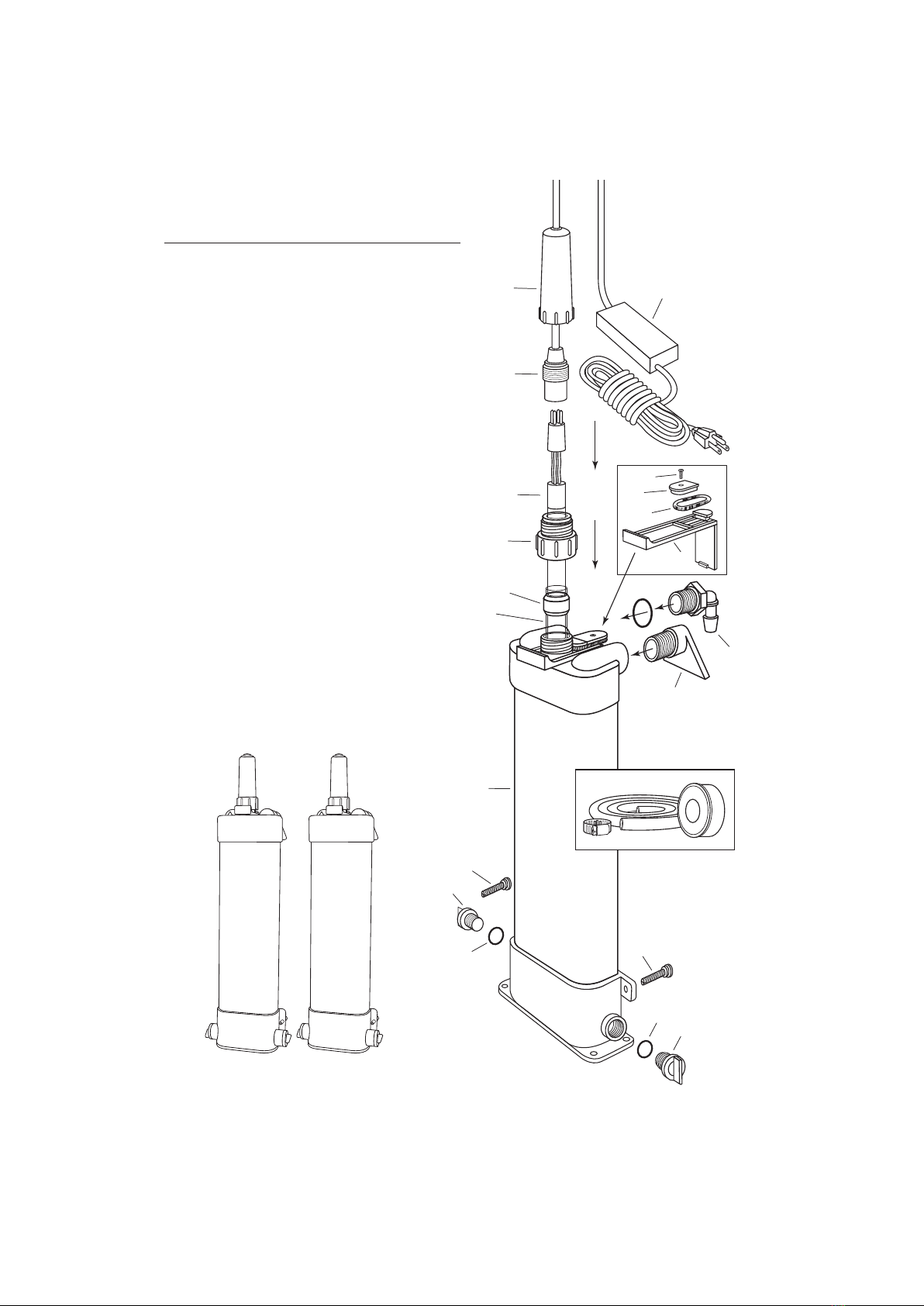
D2. Screw in the plugs on each
side of the bottom manifold.
Make sure the plug “O” rings
are seated properly. In most
cases, the bottom inlet ports
will not be needed in this type
of installation. In steps D2
and D4, refer to installation
drawings in section #B
(Beside the Aquarium).
D3. Wrap thread seal tape on the
male threads of the two 3/4”
MPT x 1/2” barb elbow ttings
provided. Wrap each tting
5-7 times with the tape.
D4. Screw one 3/4” MPT x 1/2” barb elbow tting into the top inlet port.
Screw in the other elbow tting into the outlet port located at the top
of the unit.
D5. Turn o the valve on the outlet side of the canister lter and
completely drain the exible tubing on the outlet side of the canister
lter. In most cases, it will be necessary to remove the “U” or “J” tube
from the back of the aquarium. Cut the exible tubing on the outlet
side of the canister lter and plumb in line a by-pass valve and “tee”
which will divert only a portion of the water from the canister lter
and into the inlet port of the top manifold. Attach hose clamp and
tighten accordingly.
D6. Attach one end of the 1/2” ID x 11/16” OD exible tubing to the 3/4”
MPT x 1/2” barb elbow located at the top outlet side of the lter.
Attach hose clamp and tighten accordingly.
D7. Place the other end of the tubing up and over the side or back of the
aquarium so that the water returns to the aquarium and agitates the
surface to aerate the system. In some cases, exible tubing can be
attached to a rigid plastic “U” or “J” tube (not supplied in this unit)
that hangs on the aquarium. Attach hose clamp to the rigid tube and
tighten accordingly. We recommend using the CustomFlo Water
System in place of the “U” or “J” tube for professional looking
installlations.
D8. Adjust the by-pass valve to direct appropriate amount of water into
the UV. See Size and Specication Chart for proper ow rate.
4