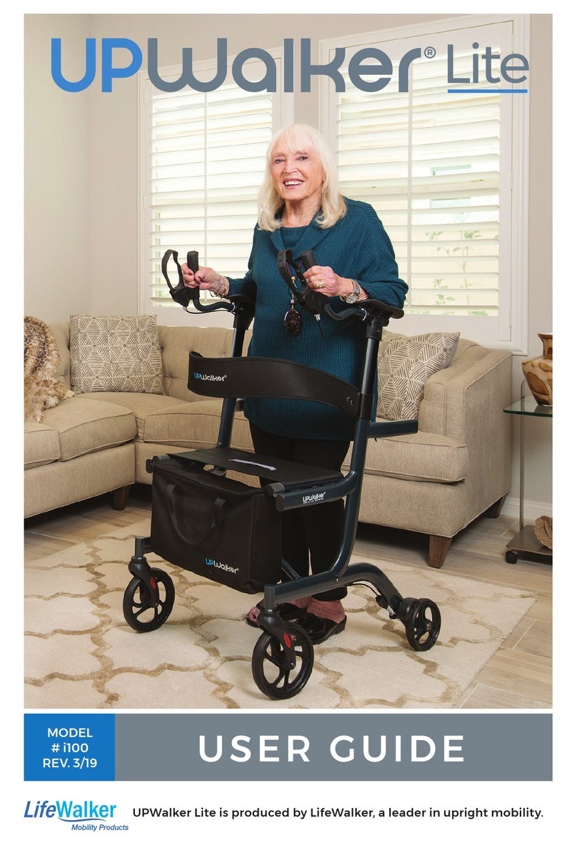
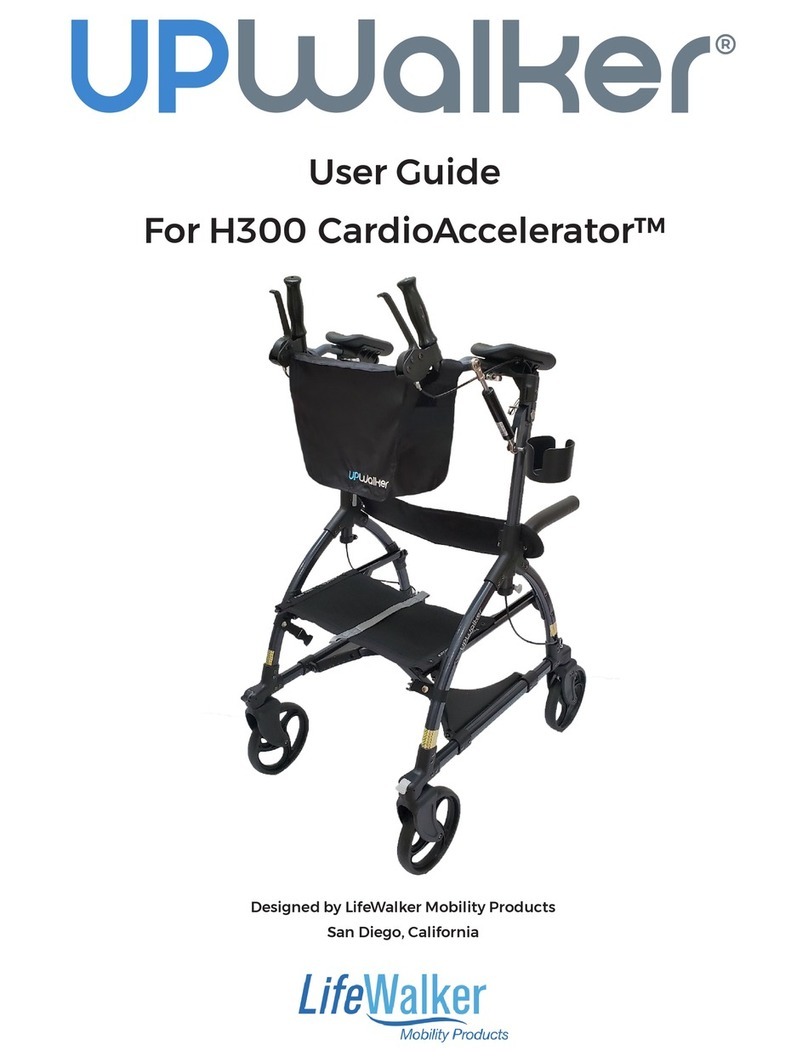
LifeWalker Mobility Products Upwalker User manual

User Guide
Designed by LifeWalker Mobility Products
San Diego, California

2
TABLE OF CONTENTS
Page
Safety Warnings 3
Set-Up Instructions 4
Product Features 5
Opening the UPWalker 6
Setting Desired Armrest Height 7
Setting Handgrip Angle 8
Setting Length of Handgrip Arm 9
How to Use Parking Brakes 10
How to Adjust Brakes 10
Positioning the Seat 12
Using Sit-to-Stand Assist Handles 12
Locking and Unlocking the Wheels 13
Closing the UPWalker 13
Using Your UPWalker 14
Maintenance 14
Accessories 15
Warranty Information 19
Customer Support 20

3
SAFETY WARNINGS
TO ENSURE YOUR SAFETY INUSING THE UPWALKER®, THE FOLLOWING
SAFETY INFORMATION AND ALL INSTRUCTIONS MUST BE FOLLOWED.
•DO NOT use this product without first reading and understanding the
instructions contained in this booklet.
•DO NOT exceed 300lb (136kg) weight limit.
•User assistance is recommended for customers with fall risk.
•DO NOT use the UPWalker if there is apparent damage or if any parts
(other than accessories) are missing.
•Care should be taken to ensure that all height adjustment locks, handles,
brakes or any other functional or moving parts are in good working order
before operation.
•Periodically check engagement of seat rail in frame and armrest height
adjustments to make sure they are secure.
•DO NOT use with rear wheels in unlocked position.
•DO NOT ride the UPWalker with all your weight on the armrests or lean
disproportionately on one of the armrests.
•DO NOT use on stairs, escalators, moving sidewalks, or uneven surfaces.
•DO NOT go up or down inclines greater than 15% or diagonally across
inclines greater than 5%.
•Be careful to avoid pinching your fingers while raising and lowering
the armrests and opening and closing the UPWalker frame.
•ALL WHEELS must be in contact with the floor at ALL TIMES. This will
ensure that the UPWalker is properly balanced.
FAILURE TO FOLLOW THESE INSTRUCTIONS CAN LEAD TO SERIOUS
INJURY OR DEATH. FOR SAFETY AND WARRANTY COMPLIANCE, THE
UPWALKER IS ONLY TO BE USED BY A CONSUMER IN A MANNER AS
DEMONSTRATED FOR INTENDED USE AS A MOBILITY ASSISTANCE
DEVICE. MISUSE OF THE UPWALKER MAY VOID WARRANTY.

4
SET-UP INSTRUCTIONS
1. Unbox the UPWalker on a level floor. Carefully remove the UPWalker
from the box and remove protective plastic and all cardboard pieces.
Retain shipping materials in the event of customer return of product.
2. Stand the UPWalker up on all four wheels (see Fig A1 on page 6).
3. Push the front wheel gray lock tabs down to release the front wheels
from locked position (see “Locking and Unlocking Wheels” on page 13).
4. The rear wheels will automatically lock in place when turned backward
(see “Locking and Unlocking Wheels” on page 13).
5. Open the UPWalker (refer to “Opening the UPWalker” on page 6).
6. Adjust armrest height to your desired user height (refer to “Setting
Desired Armrest Height” on page 7).
7. Set handgrip orientation to your desired angle (refer to “Setting
Handgrip Angle” on page 8).
8. Set handgrip extension to your desired length, or leave in current
position if comfortable (refer to “Setting Length of Handgrip Arm”
on page 9).
9. Check the brakes for normal function, including the parking brake
function (refer to “How to Adjust Brakes” on page 10).
10.With parking brakes off (see “How to Use Parking Brakes” on page 10),
ensure that all four wheels spin freely.
11.Follow instructions on page 6 for securing seat in forward position, with
seat rails pushed firmly inside support brackets on frame, before using
the UPWalker.
12.Examine all other parts for shipping damage. DO NOT use the UPWalker
if there is apparent damage or if any parts (other than accessories) are
missing. If there are missing or damaged parts, please contact
LifeWalker Customer Service at 866-588-1845 or
customerservice@lifewalkermobility.com.

5
UPWalker®
Product Features
Armrest Pad
Adjustable Foam
Handgrip
Height Adjustment
Tube
Backrest Support
Beverage Holder
Parking /
Hand Brake
Height Adjustment
Memory Stop
Sit-to-Stand
Assist Handles
Personal Item Bag
Moveable Seat
Eight Inch Rubber
Wheels
(for indoor or
outdoor use)
Front Wheel
Locks
Sturdy Metal
Frame
Seat Rail

6
A. Opening the UPWalker:
1. To open the UPWalker, begin by standing the
UPWalker on all four wheels on a level floor (Fig A1).
2. Open the Velcro strap on front legs of the frame to
enable opening of the UPWalker (Fig A2). Stow the
strap by wrapping around attached frame and
securing with Velcro.
3. Standing behind the UPWalker, lift up slightly on
the sit-to-stand assist handles while pulling outward
in opposite directions to open frame (Fig A3).
4. Continue opening the UPWalker by pushing
slightly inward simultaneously on the sit-to-stand
assist handles to align and connect seat rails with
frame (Fig A4).
5. To complete opening of the UPWalker, move
seat to most forward position (Fig G1) and push
downward on the seat where marked “Push Down
To Secure” until seat rails sit securely inside the
support brackets on frame (Fig A5).
CAUTION: THE UPWALKER IS NOT SECURE FOR USE IF SEAT RAILS ARE
NOT PUSHED FIRMLY INTO THE FRAME BRACKETS AS DEMONSTRATED
IN FIG A6. DO NOT USE THE UPWALKER IF SEAT RAILS ARE OUT OF
FRAME BRACKETS (FIG A7).
Fig A6
Fig A7
Fig A2
Fig A4
Fig A3
Fig A1
Fig A5

7
B. Setting Desired Armrest Height
1. The armrests on the UPWalker are raised and lowered independently
of each other. It is recommended that the armrests be set at the same
height. Should the user have a physical condition that requires offsetting
the height of the armrests, the armrests can be set accordingly for
comfort.
2. To raise and lower the armrests, first
push in the light gray height adjustment
tab (Fig B1) and, while keeping the tab
depressed with one hand, use your other
hand centered over armrest pad to raise or
lower the armrest to the desired height
(Fig B2). When the armrest is at the desired
height, release the height adjustment tab
to automatically engage the tab’s pin in the
tube hole. You will hear a “click” when the
tab is engaged. Avoid pinching your fingers
between the armrest and the top of the
height adjustment tube while raising or
lowering the armrests.
CHECK THAT THE HEIGHT ADJUSTMENT TABS ARE SECURELY IN PLACE
BEFORE PLACING WEIGHT ON THE ARMRESTS AND WALKING IN THE
UPWALKER.
3. The armrest should be set at a height that is high enough that you feel
support under your forearms when standing upright inside the UPWalker
but not so high as to cause your shoulders to “hunch.” Put equal weight
on each forearm while using the UPWalker. You may find it beneficial to
displace some of your body weight on your forearms while walking.
4. Each setting is marked with a number on the height adjustment tube
for future reference. Note and remember the setting you prefer.
Fig B1
Fig B2

8
5. The UPWalker includes a convenient
height adjustment memory stop on the
bottom of each height adjustment tube
(Fig B3). After you have established your
preferred height setting, unlock the height
adjustment memory stop using the gray
knob, turning it in a counterclockwise
direction. Slide the memory stop up to the frame and
relock in place by turning the gray knob in a clockwise direction until
tight. Once set you may raise an armrest from a lowered position until
the memory stop is reached. The memory stop does not need to be
moved again unless a different armrest
height is required.
C. Setting Handgrip Angle
1. To set the handgrip at the desired
angle, open the chrome cam lever under
the armrest pad and swivel the handgrip
to the preferred position (Fig C1).
2. There are three suggested handgrip
positions – horizontal (Fig C2), vertical (Fig
C3) or 45 degrees (Fig C4) (where you will
feel a slight “stop” as you swivel the
handgrips). The handgrip angles can be set at
other angles, if that suits the user.
3. Once the preferred angle is established,
close the chrome cam lever firmly to secure
the handgrip in place (Fig C6). The tightness
of the cam lever can be adjusted by turning
the cam lever nut on the outer side of the
armrest.
Fig B3
Fig C1
Fig C2
Fig C3

9
4. To close the UPWalker to its most compact size for storage or
transport, point handgrips directly downward or upward in a vertical
position so they don’t conflict when folding (Fig C5 or C3).
D. Setting Length of Handgrip Arm
1. The UPWalker is shipped with the
handgrips set in the extended length
position relative to the armrest pads.
This default length should fit most
users.
2. Should the user want to shorten the
reach from the armrest pads to the
handgrips, first release the chrome cam
lever under the armrest pad (Fig D1).
3. Swivel the handgrip arm inward to
access the brass pin (Fig D2) in the slot
under the armrest pad, depress the pin
and pull the handgrip backward until
the second (originally unexposed) pin
locks in the slot (Fig D3). Return
handgrip to desired angle and close the
cam lever (Fig C6).
4. Repeat on both sides so the reach is
uniform left and right.
Fig C6
Fig C5
Fig C4
Fig D1
Fig D2
Fig D3

10
To lengthen the reach of the handgrip, release the cam lever and swivel the
handgrip arm, push in the brass pins one at a time and pull the handgrip
forward until the rear brass pin engages in the slot. Return handgrip to desired
angle and close cam lever (Fig C6).
E. How to Use Parking Brakes
1. To set parking brake, push the brake
handle forward until it clicks in locked
position. Some users may want to hold the
handgrip with one hand while using the
other hand to push the brake handle
forward. (Fig E1).
2. To unlock brakes, simply pull brake handles back toward you.
3. It is strongly recommended that the parking brakes be set in the
locked position when the user is sitting down in the UPWalker or standing
from a seated position and when the user is making adjustments to the
UPWalker’s settings.
4. When using brakes while walking, both
brakes should be applied with equal
pressure.
F. How to Adjust Brakes
The following information is intended to
assist you with the adjustment of your
brakes.
Note: The brakes on your new UPWalker
have been preset from the factory. Due to
normal use over time you may need to make
adjustment to maintain this setting. You can
adjust the brakes by making the following
adjustments at either the brake handle position (Fig F1) or above the rear
Fig E1
Fig F1
Fig F2

11
wheel (Fig F2). Before attempting to adjust the brakes, ensure that the
parking brake is disengaged (see "How to Use Parking Brakes" page 10).
Brake is Too Loose
Use fingers or pliers to turn the barrel
adjuster nut counterclockwise a half
rotation (Fig F3). Try the brake. If this does
not correct the problem, repeat turning the
barrel adjuster nut a half rotation at a time
until the brake functions as expected. Then
turn the larger locking nut clockwise using
fingers or a 10 mm or 13/32 wrench until it
presses tightly against the housing to prevent the barrel adjuster nut from
loosening.
Brake is Too Tight
Use fingers or a 10 mm or 13/32 wrench to turn the larger locking nut
counterclockwise until loosened. Then use fingers or pliers to turn barrel
adjuster nut clockwise a half rotation (Fig F3) and try the brake. If this does
not correct the problem, repeat turning the barrel adjuster nut a half
rotation at a time until the brake functions as expected. Then turn the
locking nut clockwise until it presses tightly against the housing to prevent
the barrel adjuster nut from loosening.
Resetting the Brakes
NOTE: DO NOT ATTEMPT TO PERFORM THIS TASK IF
YOU ARE NOT MECHANICALLY INCLINED.
If you cannot achieve the desired adjustment by
means of the above, you may use a 4 mm or 5/32”
Allen wrench to reset the brake using the brake
cable nut attached to the brake pad at each rear
wheel (Fig F4). First loosen the nut by turning Allen
wrench counterclockwise. Once loosened, you may
pull the brake cable out of the nut to tighten the
brake, or push the brake cable into the nut to loosen the brake. After
achieving desired cable length, tighten the nut by turning clockwise. You
may have to repeat adjustment a few times to get it right.
If you are not comfortable with adjusting your brakes please consult a local
Durable Medical Equipment dealer or contact LifeWalker Customer Service
Fig F3
Fig F4

12
at 866-588-1845 or customerservice@lifewalkermobility.com. Please note,
LifeWalker does not reimburse customers for maintenance charges on the
UPWalker, including brake adjustments.
G. Positioning the Seat
1. To walk in the UPWalker, pull the seat to the most forward position by
lifting up and pulling forward the tab on the front of the seat (Fig G1).
2. To sit on the seat, set the parking brake, pull the seat fully backward
using the rear pull tab (Fig G2), and sit with legs facing the rear. Sitting on
the seat with the armrests in their raised position is often preferred.
3. Use the sit-to-stand assist handles as needed when sitting and
standing (Fig G3).
H. Using Sit-to-Stand Assist Handles
1. Move rear wheels of the UPWalker under the chair in which you are
seated, aligned with your feet.
2. Set parking brakes (see “How to Use
Parking Brakes” on page 10).
3. Place hands on left and right sit-to-stand
assist handles.
4. Bend over to where your nose is over your toes and push down on the
sit-to-stand assist handles to stand up into the UPWalker (Fig H1).
5. Release parking brake (see “How to Use Parking Brakes” on page 10)
Fig G3
Fig H1
Fig G1
Fig G2

13
I. Locking and Unlocking the Wheels
1. For most users the front wheels should be
set to pivot freely and allow the UPWalker to
turn left and right. This is achieved by placing
the light gray tab above each front wheel in
the down position (Fig I1). However, the front
wheels can be locked to roll only in a straight
line by flipping the gray wheel lock tabs to the
up position (Fig I2).
2. The rear wheels should be kept in the
locked position when using the UPWalker. If
you need to unlock the rear wheels to reduce
the size of the unit for shipping, storage or
transport, lift up the black wheel lock tabs
above the rear wheels (Fig I3) and pivot the
wheels inward. Push wheel lock tabs down to
closed position after turning wheels under the
UPWalker.
J. Closing the UPWalker
1. Lower the armrests to the lowest setting
(see “Setting Desired Armrest Height” on
page 7). Lift the seat up by seat lift handle
(Fig J1) and allow UPWalker to fold in (Fig J2).
Stand the UPWalker on all four wheels to roll
or stow. Use the Velcro strap on front of the
UPWalker to secure folded unit for storage or
transport.
2. When folding for storage or transport, it is
recommended that the handgrips be turned
either vertically upward (Fig C3) or fully
downward toward the ground (Fig C5), and
the armrests should be returned to their
lowest height position (Fig A1).
3. Luxury Personal Item Bag must be removed to avoid damage to bag.
Fig I1
Fig I2
Fig I3
Fig J1
Fig J2

14
K. Using Your UPWalker
1. Once standing in the UPWalker move forward so your body is between
the armrest pads, standing in an upright position with good posture.
2. Put equal arm pressure on the left and right armrest pads. Put hands on
handgrips with fingers around the brake handles. Take full-stride steps
with constant gait.
3. Pull on brake handles while going down hills to control speed.
4. Walk regularly for exercise to maintain good health.
L. Maintenance
1. Check your UPWalker periodically to make sure that the brakes are
working correctly and that all of the nuts and bolts are secure. Do not use
the UPWalker if the brakes are not working correctly.
2. If handgrips are loose, do not use the UPWalker.
3. Periodically inspect the wheels for tightness, wear and damage. Before
use, make sure that the wheels are free of hair, lint, dirt and other debris.
4. Regular inspection of parts including hardware, brackets and plastics
for deformation, corrosion, breakage, wear, dents or compression is
highly recommended.
5. Regular cleaning of the UPWalker is recommended. Wipe all surfaces
with a damp cloth and allow the surfaces to dry before use.
6. UPWalker foam handles and pads are made of closed cell material so
they can be sanitized with antiseptic cleansers.
7. Teflon or silicone lubricant may be applied to a rag and run over the
armrest height adjustment tubes and seat rail slide, after cleaning, to
assure smooth operation.

15
M. Accessories
The UPWalker is shipped to customers with the following standard
accessories:
●Backrest Support (Fig M1) is attached by sliding each end over the
sit-to-stand assist handles (Fig M2) with mesh material facing the rear end
of the UPWalker. Backrest may be left permanently on the UPWalker or
removed when not in use.
●Personal Item Bag (Fig M3) has Velcro straps which go over the handgrip
tubes at the bent sections (located below handgrips) and attach to the
opposite-side Velcro (Fig M4). The UPWalker logo is designed to be on the
front side of the bag facing away from you when using the UPWalker.
●Beverage Holder (Fig M5) can be attached to either one of the handgrip
tubes. First, unscrew the knob on U-shaped tube clamp and remove the
beverage holder from the U-clamp. Then slide “U” over handgrip tube (Fig
M6) close to armrest pad with hole on bottom and flat side of “U” facing
inward. Make sure rubber sleeve remains inside the “U”. Slide the bolt on
beverage holder through the hole on “U” with beverage holder positioned
on the outside and the knob on the inside of the UPWalker (Fig M7). Note
Fig M1
Fig M2
Backrest
Fig M3
Fig M4

16
that the “U” and holder have a matching positioning key to rotate and lock
the holder at the desired angle. Additional adjustments can be made to the
positioning of the beverage holder by moving the “U” on the handgrip tube.
Optional Accessories
Also available for purchase from LifeWalker’s website:
●Shopping Bag (Fig M8) sits on the seat when seat is placed
in the forward position under handgrips. Support straps
should be placed in the bend in the handgrip tubes at the
base of each handgrip. Secure support straps using the
Velcro material at the ends of the straps (Fig M9). Note
that the shopping bag has convenient handles to transport
your purchases by hand.
●Luxury Personal Item Bag (Fig M10) is constructed with
premium materials and includes a secure zipper top and
side pockets to hold additional personal items. With the
UPWalker logo facing forward, place support straps in the
bend in the handgrip tubes at the base of each handgrip
and secure using Velcro at the ends of the straps (Fig
M11).Remove bag before folding UPWalker.
Fig M5
Fig M7
Fig M6
Fig M8
Fig M9
Beverage
Holder
Fig M10
Fig M11

17
●Smartphone Holder (Fig M12) supports different sizes of
phones for handsfree operation when you are on the go.
To attach the holder, first unscrew the cam lever nut
under the right armrest pad opposite the chrome cam
lever which secures the handgrip tube. Mate the hole in
the end of the flexible phone holder arm with the cam
lever bolt and the plastic base holding that bolt. Re-
attach and tighten the nut (Fig M13). Close cam lever to
secure both handgrip arm and smart phone holder. It
may be necessary to adjust the cam lever tension by
turning the cam lever nut clockwise or counterclockwise.
Two round adjuster knobs are located on the back of the
smart phone holder (Fig M14). Use the larger knob to
adjust the size of the holder to accommodate different
sizes of phones. Turn large knob counterclockwise to
open and insert phone, then turn knob clockwise to close
holder. Secure the phone in place by turning the small
knob clockwise. The phone holder is attached to a
flexible arm which can be bent to turn phone to desired
position (hold arm firmly where it attaches under
armrest while bending phone end, so as not to
break the attachment mechanism on the
UPWalker). The phone holder can be pivoted
on the flexible arm to optimize viewing of the
phone. Untighten/tighten the adjuster knob at
the end of the arm to pivot the phone holder.
●Cane/Umbrella Holder (Fig M15) attaches to
the side of the UPWalker for the convenience
of holding a cane or umbrella
handsfree. The cup attaches to the
lower horizontal frame tube facing
outward near front wheels (Fig M16).
To attach the cup, first turn the cup
to remove from the cup attachment
clamp. Then remove the bolt with
light gray knob from the clamp.
Spread the “U” clamp over the lower
horizontal tube with the knob on the
Fig M16
Fig M12
Fig M13
Fig M14
Fig M15

18
outside and the retaining nut on the inside. Slide bolt
with knob back through the holes on clamp and turn
the knob clockwise to seat the bolt in the retaining nut
and tighten clamp against frame. Re-attach the cup
and turn to desired position.
The upper retaining clamp attaches to the curved front
leg tube of frame, with clamp and gray knob on the
outside of the frame (Fig M17). To attach the clamp,
remove bolt with knob from the clamp. Spread the “U”
clamp over the frame with the knob on outside of
frame. Slide bolt with knob back through the holes on
clamp turning knob clockwise to tighten clamp against
frame. After attachment, turn retaining clamp to desired position to secure
cane or umbrella.
●Safety Flashlight / Taillight can be attached to the left
or right handgrip tubes (Fig M18) facing forward as a
headlight (Fig M19) or backward as a taillight. As with
other accessories, there is a “U” clamp which must be
spread open so as to place the clamp on the handgrip
tube with the light on the outside and holes for bolt on
the inside. Unscrew and remove the bolt and knob to
open clamp, attach clamp over tube and replace bolt
and knob with the bolt sliding in from the top and the
knob on the bottom of clamp.
Once attached you may aim the light in a downward
position to illuminate area in front of you or turn and
aim behind you so others can see you. The light is
turned on by depressing the button found on the back.
Push once for light to stay on; push a second time to
blink like a strobe light; push a third time to turn off.
The lens on the front of the light can be moved
outward or inward to change the size and shape of the
light beam. To insert the three AAA batteries (not included),
unscrew the cap on the back of the light, remove battery
holder and insert batteries in holder with batteries properly aligned with +/-
signs. Insert battery holder back into flashlight and resecure the cap.
Fig M17
Fig M18
Fig M19

19
WARRANTY INFORMATION
LifeWalker Mobility Products stands firmly behind our commitment to
provide premium quality products. Our standard warranties represent our
confidence in the materials and workmanship of your new UPWalker.
The frame of the UPWalker is warrantied to be free from defects in
material and workmanship, under NORMAL use, for the lifetime of the
original consumer purchaser when purchased from LifeWalker Mobility
Products or an authorized LifeWalker Mobility Products dealer. Accessories
and non-durable components such as wheels, brakes, seat, handgrips, and
armrests, which are susceptible to normal wear and tear and subject to
periodic replacement, are warrantied for six (6) months.
During these warranty periods, our warranties cover all parts, labor and
shipping for repairing the UPWalker. Our warranties expire on their
respective anniversaries and immediately upon any sale or transfer of
ownership or use of the product to another person.
Our warranties do not cover the following:
A product that was modified or repaired without prior written
authorization from LifeWalker Mobility Products or an authorized
LifeWalker Mobility Products dealer.
Routine brake adjustments.
Problems arising from:
●User negligence.
●Any failure to adhere to the UPWalker user and maintenance
instructions.
●Any abuse or misuse of the product for purposes other than those
specified in the UPWalker User Guide.

20
CUSTOMER SUPPORT
For customer support on the purchase, use, maintenance and repair of your
UPWalker, please contact LifeWalker Customer Service at 866-588-1845 or
customerservice@lifewalkermobility.com. When contacting us, please have
available the following information:
●The date of your purchase and form of payment.
●The product serial number.
●A description of the defect or problem requiring service.
DO NOT return any products to LifeWalker Mobility Products without our
prior authorization.
If you purchased your UPWalker from an authorized LifeWalker Mobility
Products dealer, please contact that dealer. If you do not receive satisfactory
service from the dealer, please call LifeWalker Mobility Products.
LifeWalker Mobility Products
9530 Chesapeake Drive
Suite 501
San Diego, CA 92123
www.LifeWalkerMobility.com
UPWalker®, LifeWalker® andProtoStar® aretrademarks ofProtostar, Inc.,
dba LifeWalker Mobility Products
Patent pending
Table of contents
Other LifeWalker Mobility Products Mobility Aid manuals
LifeWalker Mobility Products
LifeWalker Mobility Products UPWalker H200 User manual

LifeWalker Mobility Products
LifeWalker Mobility Products UPWalker Lite i100 User manual

LifeWalker Mobility Products
LifeWalker Mobility Products UPWalker Lite User manual

LifeWalker Mobility Products
LifeWalker Mobility Products UPWalker CardioAccelerator H300 User manual