Ligao JLM-S User manual

Instruction Manual
JLM-S Solenoid Metering Pump
Carefully read and understand all precautions
before installing and servicing.


CONTENT
1 Precautions............................................................................................. 1
2 Product Introduction.............................................................................. 3
2.1 Overview...................................................................................... 3
2.2 Technical Parameter................................................................4
2.2.1 General Parameter......................................................... 4
2.2.2 Performance Parameter.................................................5
2.2.3 Installation Drawing.........................................................5
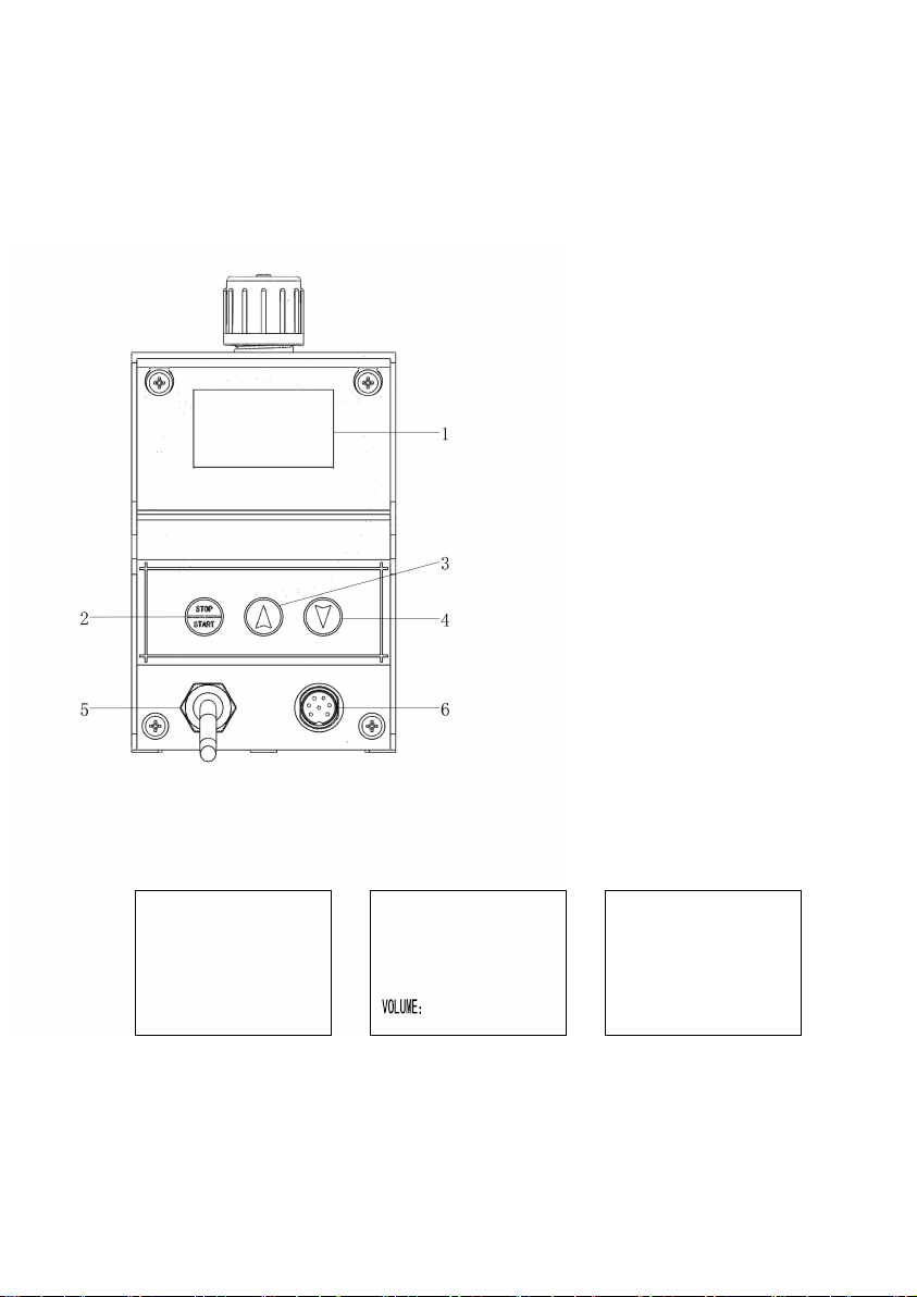
2.3 Operation Instruction..................................................................6
2.4 Unpacking Check List........................................................................ 7
3 Installation............................................................................................... 8
3.1 Pump Installation........................................................................ 9
3.2 Tubing Connections................................................................. 14
3.3 Food Valve and Suction Tubing Installation......................... 14
3.4 Injection Valve and Discharge Tubing Installation.............. 15
3.5 Air Release Valve Installation................................................. 16
4 Operation and Setting......................................................................... 17
4.1 Start-Up and Priming............................................................... 17
4.2 Setting.........................................................................................18
4.3 Signal Connector Description......................................................... 27
4.4 Calibration..................................................................................27
5 Maintenance and Repair.....................................................................29
5.1 Maintenance.............................................................................. 29
5.2 Diaphragm Replacement........................................................ 30
5.3 Check Valves Replacement....................................................33
6 Troubleshooting.................................................................................... 34
7 Main Parts List...................................................................................... 36
Appendix................................................................................................... 39

1
1 Precautions
The following precautions should be taken when operating
metering pumps. Please read all sections carefully prior to
installation.
Protective Clothing
Wear protective clothing, face shield, safety glasses
and gloves when operate or near your metering pump.
Additional precautions should be taken depending on the
pumped solution. Please refer to MSDS precautions from
your solution supplier.
Water Test
All metering pumps are tested with water before
delivered from the factory. If your solution is not compatible
with water, disassemble the pump head assembly.
Thoroughly dry the pump head, check valves, seal rings,
valve balls and the diaphragm. Reassemble head
assembly and tighten the screws. Refill the pump head with
the solution before start the pump.
Tubing Connections
Inlet and outlet tubing size must not be reduced. Make
certain that all tubing is securely attached to fittings before
start-up. Always use the supplied tubing with your pump, as
the tubing is specifically designed for use with the pump
fittings. It is recommended that all tubing be shielded to
prevent possible injury in case of rupture or accidental

2
damage. If tubing is exposed to sunlight, black UV resistant
tubing should be installed. Check tubing frequently for
cracks and replace as necessary.
Plumbing Code
Please adhere to your local plumbing codes and
requirements. Be sure installation does not constitute a
cross connection. Check local plumbing codes for
guidelines. Our company is not responsible for improper
installations.
Back Pressure/Anti-Syphon Valve
If it is pumping downhill or into low or no system
pressure, a back pressure/anti- syphon valve should be
installed. Contact your local distributor for further
information.
Electrical Connections
Warning :To prevent the risk of electrical shock, the
metering pump must be plugged into a grounded power
with ratings conforming to the data plate on the pump. All
wiring must confirm to local electrical codes. If the pump
power cable fails, change it by the factory, distributor or
authorized repair shop, in case cause any injury.
Warning:To prevent the risk of electrical shock, install on a
circuit protected by a ground-fault circuit-interrupter.

3
Tubing Depressure
All tubings should be depressured when
disassembling or maintenance, in order to prevent solution
from splashing.
Over-pressure Protect
Suggest install safety/pressure relief valve, to prevent
over pressure causing the pump or system damage.
2 Product Introduction
2.1 Overview
JLM-S metering pump is a microprocessor controlled
solenoid diaphragm pump with changeable frequency. It is
capable for all kinds of solutions dosing, including corrosive
solutions. It is widely used in petroleum, chemical, food,
pharmaceutical, paper, light industry, agriculture, water
conservancy and other industrial and technological sectors,
in the process solution metering and dosing.
Solenoid metering pump is the use of electromagnetic
push rod driven diaphragm in the pump head reciprocating
movement, causing the pump head chamber volume and
pressure changes. Changes in pressure caused by suction

4
valve and discharge valve opening and closing, to achieve
quantitative liquid suction and discharge.
JLM-S solenoid metering pump rated flow range is 1 ~
20 l / h, with corresponding maximum output pressure of 10
~ 1bar. The pump outlet displacement can be adjusted
according to the pulse frequency selection switch. It is a
simple structure, low energy consumption, accurate
measurement, with a new screen display of
electromagnetic diaphragm metering pump.
2.2 Technical Parameter
2.2.1 General Parameter
Metering Precision:± 2% in stable condition
Allowable Ambient Temperature:-10℃~+45℃
Power:AC 220V or AC110V
Frequency:50Hz ~ 60Hz
Input Power:
Stroke Frequency
Rated Power
90 strokes/min
120 strokes/min
180 strokes/min
16W
20W
28W

5
Protection Class; IP65
Insulation Degree: F
Outer Connection Control:Passive Contact Pulse Signal
Contact Load:5V,0.5mA
2.2.2 Performance Parameter
Model
Flow
L/H
Pressure
Bar
Frequency
Stroke/min
Caliber
mm
JLM-S0110
1.0
10
110
¢5
JLM-S0408
3.8
7.6
130
¢5
JLM-S0607
6.3
6.8
160
¢5
JLM-S0805
8.0
5.0
170
¢5
JLM-S1204
12
4.0
150
¢5
JLM-S1502
15
2.5
170
¢5
JLM-S2001
20
1.0
180
¢5
2.2.3 Installation Drawing

6
2.3 Operation Instruction
Stop State Running State Setting State
1 Display Screen
2 Stop/Start Button
3 Increase Button
4 Decrease Button
5 Power Cable
6 Signal Plug
0 %MANUAL
AUTO
REMOTE
SET:
FLOW:
12.88L/H
1999.9L
100 %
180
0

7
2.4 Unpacking Check List
Your carton will contain all or some of the following
items. Please notify the carrier immediately if there are any
signs of damage to the pump or its parts.

8
3 Installation
Due to the possibility of water residue at the factory test,
if the metered solution can not be in contact with water,
water must be removed before starting use and the inside
of the pump head can be flushed through the suction side
with suitable solution.
The metering pump should be installed near the dosing
tank , where the power supply is convenient. If the pump is
exposed directly to the sun, a black UV shield should be
installed.
The installation location of the metering pump should
be convenient for personnel to access, operate and
maintain, and do not have any obstructions in the work
area.
If the shut-off valve is closed at the discharge side of
the metering pump, when the shut-off valve is closed, the
back pressure generated by the metering pump may be
several times the maximum allowable back pressure, which
may cause the discharge tube to rupture. To prevent this
from happening , It is recommended to use a relief valve to

9
limit the maximum back pressure within the allowable
value.
Only use the hose diameter corresponding to the hose,
hose connector and the provisions of the specifications of
the hose, or can not guarantee the connection of a solid
and lasting. Do not reduce the hose specifications. Longer
pipelines or medium viscous use larger cross-section
pipelines and pulsating dampers.
3.1 Pump Installation
To ensure safe operation of the metering pump, tighten
with bolts.
To ensure proper operation, the metering pump inlet
and outlet must be kept vertical during installation.
The pump has the following two installation methods:
A. Flooded Suction(ideal installation)
This method is installed by installing the pump on the
base of the storage tank. This installation is the most easy,
suitable for low flow, volatile, high viscosity solution. As the
suction tube filled with the solution, the pump can quickly
self-priming, and the chance of priming failure rarely occurs.

10
This type of installation does not require a bottom valve. If it
is transported downwards or transported to a low or low
pressure place, install a back pressure valve or an
anti-siphon valve. All solutions can be used in this type of
immersion, but this is especially recommended for high
concentrations of liquids.

11
Note:
The following figure is typical wrong installation.

12
B. Suction Lift;
Tank Mount: The pump is mounted on the top of the
solution tank.

13
Wall Bracket Mount:The pump is mounted on the wall
with bracket above the solution tank. This method allows
for easy changing of the solution tanks.

14
3.2 Tubing Connections
Insert tubing through coupling nut
and clamp.
Cut the hose at suitable length, and
insert the nozzle as deep as possible.
Enlarge the diameter of the hose if
needed.
Press the clamp and tighten the coupling nut.
3.3 Food Valve and Suction Tubing Installation
The bottom valve acts as a check valve, allowing the
pump to self-priming in the case of a suction installation.
The bottom valve must be dipped vertically into the bottom
of the dosing medium. If the medium contains a precipitate,
the bottom valve should be located approximately 50 mm
from the bottom of the tank.
Ceramic weight can make foot valve and suction tube
in vertical position.
Attach the foot valve to one end of the suction tubing

15
(see section 3.2).
Slide the ceramic weight over the tubing end until it
contacts the top of the foot valve coupling nut.
Place foot valve and suction tubing into the solution
tank. Check if the foot valve is vertical and approximately
50mm from the bottom of the tank. Connect the other end
of the tubing to the suction side of the pump head(see
tubing connection, section 3.2).
3.4 Injection Valve and Discharge Tubing
Installation
Injection valve prevents backflow. Install the injection
valve at the location where chemical is being injected into
the system. (see tubing connection, section 3.2)
When installing the injection valve, make sure that
the valve is vertical to the bottom of the tube and that the
left and right errors are within 80 degrees.

16
3.5 Air Release Valve Installation
Air release valve with exhaust sampling function. The
valve is mounted on the outlet check valve and is
connected to the hose to allow the medium to return to the
dosing tank.
In order to ensure smooth self-absorption, the tube
can not be immersed in the medium.

17
4 Operation and Setting
4.1 Start-Up and Priming
Please read the following carefully before proceeding
to the next step. After all the protective measures are done,
the pump is installed, the pipe is firmly connected, open all
the control valves on the inlet and outlet lines, you can start
priming the pump head.
Connect the power.
When the pump is running, slowly increase the pulse
frequency.
Suction tubing should begin to fill with solution from the
tank.
A small amount of solution will begin to discharge out
the discharge valve.
The pump is now primed.
The pump has a self-priming function (except for
special conditions). If the pump does not self-prime,
remove the discharge check valves, pour water or solution
into the pump port until the head is filled. Install back the
Table of contents
Popular Water Pump manuals by other brands

AquaCharge
AquaCharge AquaCharge owner's manual

entegris
entegris INTELLIGEN MV Installation and use manual

Stryker
Stryker IsoTour Standard 2874 Maintenance manual

QED
QED WELL WIZARD installation guide

BLACKMER
BLACKMER EBSRAY RC20 Installation, operation and maintenance instructions

Grundfos
Grundfos DMX 221 instructions