manuals.online logo
Brands
  1. Home
  2. •
  3. Brands
  4. •
  5. MasterCraft
  6. •
  7. Water Pump
  8. •
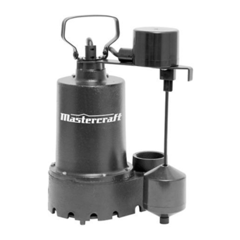
  9. MasterCraft 062-3535-2 User manual

MasterCraft 062-3535-2 User manual

IMPORTANT:
Please read this manual carefully before running this
submersible sump pump and save it for reference.
INSTRUCTION
MANUAL
Submersible
SUMP PUMP
Model No. 062-3535-2
3
NOTE:
If any parts are missing or damaged, or if you have any questions, please call our
toll-free helpline at 1-800-689-9928.
SAVE THESE INSTRUCTIONS
This manual contains important safety and operating instructions.
Read all instructions and follow them with use of this product.
TABLE OF CONTENTS
4
6
8
11
12
Quick Start Guide
Technical Specifications
Safety Guidelines
Key Parts Diagram
Assembly Preparation
13
14
15
16
17
Assembly Instructions
Operating Instructions
Maintenance
Troubleshooting
Warranty
TABLE OF CONTENTS
model no. 062-3535-2 | contact us 1-800-689-9928
4
QUICK START GUIDE
SUMP REQUIREMENTS
Pit must be covered. It is usually
10" (25.4 cm) in diameter and
14" (35.6 cm) deep.
Install on a hard surface: brick,
cement, or concrete block;
not sand, clay, or gravel.
1
DISCHARGE PLUMBING
To install the discharge plumbing and
check valve on the pump:
A. Use non-stick tape—NOT pipe joint
compound.
B. Tighten the pipe into the pump.
C. Install the check valve as close to
the pump as possible.
D. Drill an 1/8" (3 mm) anti-airlock hole as
shown. The hole must be in the sump.
2
INSERTING THE PUMP
Place the pump in the sump,
making sure that nothing interferes
with switch operation.
3
1 1/4" (3.2 cm) or
1 1/2" (3.8 cm)
Discharge Pipe
Check Valve
1/8" (3 mm)
Anti-airlock Hole
PVC Threaded
Adaptor
14"
(35.6 cm)
depth
Sump Pit
10" (25.4 cm) diameter
5
WARNING!
QUICK START GUIDE
COMPLETING THE PLUMBING
Finish installing the necessary
plumbing. Follow the glue
manufacturer’s instructions for
curing time.
4
VERIFYING OPERATION
Check the pump’s operation by filling
the sump with water until the pump
starts. Let it run until it has pumped
down the sump and stopped. Replace
the sump cover.
5
PLUGGING IN THE PUMP
Plug the pump into a 15 A
circuit.
The circuit should be GFCI protected
and dedicated to the sump pump.
Plastic pipe glue is extremely flammable. Follow the glue manufacturer’s instructions
carefully if you are using glued plastic pipe for the discharge pipe.
Install in compliance with all applicable laws, codes, and ordinances. Non-compliance may
cause product failure, property damage, and/or personal injury.
Do not use an extension cord with a sump pump.
Regularly inspect pump inlet and clean away any debris.
6
TECHNICAL SPECIFICATIONS
MOTOR AND ELECTRICAL
SKU number 062-3535-2
rellepmI
Solids handling 1/4” (6.3 mm) spherical
Upper bearing Ball bearing
Lower bearing Ball bearing
Motor protection Auto-reset thermal overload protection in motor
Maximum flow 3600 U.S. GPH (13,627 L/hr)
Maximum head height 28' (8.5 m)
Construction material Aluminum alloy for motor house; plastic for volute and
impeller
Plastic
Liquid temperature range 32 to 95°F (0 to 35°C)
Single phase Permanent split capacitor (PSC)
Motor NEMA L, torque curve, oil-filled, squirrel cage induction,
class B insulation
Seal Lip seal
Discharge size 1 1/2" (3.8 cm) female national pipe thread (FNPT)
or 1 1/4" (3.2 cm) FNPT (with adaptor)
Cord length 10' (3 m)
Cord size 18 AWG
3/1PH
115 V ACPower
06zH
0543MPR
Full load amps 7.6
Cord type SJTW
NOTE:
Do not reduce size of discharge pipe or hose below 1 1/4" (3.2 cm) diameter.
If discharge is too small, pump will overheat and fail prematurely.
This pump is designed for use in a residential sump only. Only pump
water with this pump.
model no. 062-3535-2 | contact us 1-800-689-9928
7
TECHNICAL SPECIFICATIONS
Lift in feet/
metres
0’
(0 m)
5’
(1.5 m)
10’
(3 m)
15’
(4.6 m)
20’
(6 m)
25’
(7.6 m)
U.S. gallons/
litres per hour
3600
(13,627)
3400
(12,870)
3000
(11,356)
2500
(9,463)
1900
(7,192)
1000
(3,785)
DIMENSIONS
PERFORMANCE CHART
11 1/2" (29.2 cm)
7 3/4" (19.7 cm)
11 1/8" (28.2 cm)
9 1/4"
(23.5 cm)
ON
OFF
6 3/4"
(17.2 cm)
3 3/16"
(8.1 cm)
4" (10.2 cm)
4"
(10.2 cm)
9 11/16"
(24.6 cm)
2 1/2"
(6.3 cm)
3 1/2"
(8.9 cm)
*Friction loss in piping not included in measurement.
8
SAFETY GUIDELINES
SAFETY GUIDELINES
This manual contains information that relates to protecting personal safety and preventing
equipment problems. It is very important to read this manual carefully and understand it
thoroughly before using this product.
• These precautions are intended for the personal safety of the operator and others working
with the operator. Failure to follow these instructions may result in a permanent loss of vision,
serious personal or even fatal injury, property damage and/or tool damage. Please take the
time to read and understand them.
• Wear safety glasses with side shields when operating the pump and verify that others in the
work area are also wearing safety glasses. Safety glasses must conform to both American
National Standards Institute (ANSI Z87.1) and Canadian Standards Association (CSA Z94.3)
standards requirements and must provide protection from flying particles from the front and the
sides. Failure to comply may result in moderate injury.
• The motor of this pump has a thermal protector that will trip if the motor becomes too hot.
The protector will reset itself once the motor cools down and an acceptable temperature has
been reached. The pump may restart unexpectedly if it is plugged in.
• This pump is made of high-strength, corrosion-resistant materials. It will provide trouble-free
service for a long time when properly installed, maintained, and used. However, inadequate
electrical power to the pump, dirt, or debris may cause the pump to fail. Please carefully read
the manual and follow the instructions regarding common pump problems and remedies.
• Mastercraft Canada is not responsible for losses, injury, or death resulting from a failure to
observe these safety precautions, or the misuse or abuse of pumps or equipment.
DANGER!
• Keep children away from the work area. Do not allow children to handle the pump.
• Follow all electrical and safety codes, particularly the Canadian Electrical Code, and local codes and ordinances.
• Ensure that the electrical circuit to the pump is protected by a 15 A fuse or circuit breaker.
• Disconnect the power supply to the pump, drain all water and release all pressure from the water system before
servicing any pump component.
• Risk of fire or explosion: Do not pump flammable or explosive liquids such as oil, gasoline, kerosene, ethanol, etc.
Do not use in the presence of flammable or explosive vapours. Using this pump with or near flammable liquids can
cause an explosion or fire, resulting in property damage, serious personal injury and/or death.
• Risk of electric shock: Never remove the ground terminal on the three-pronged power plug of the pump as the
ground terminal is designed for protection. Do not adjust any electrical appliance or product without disconnecting
the power supply. Do not stand on wet or damp surface or in water when the pump is connected. Avoid handling
the pump with wet hands.
• Risk of burns: Do not touch the motor housing during operation. The motor is designed to operate at high temperatures.
Do not disassemble the motor housing.
• Ensure the electrical power source is adequate for the requirements of the pump.
• Extension cords may not deliver sufficient voltage to the pump motor. Extension cords present a life-threatening
safety hazard if the insulation becomes damaged or the connection ends fall into water. The use of an extension cord
to power this pump is not permitted.
• This unit is designed only for use on 115 V (single phase), 60 Hz, and is equipped with an approved 3-conductor cord
and 3-prong grounded plug. Do not remove the ground pin under any circumstances. The 3-prong plug must be
directly inserted into a properly installed and grounded 3-prong, grounding-type receptacle. Do not use this pump
with a 2-prong wall outlet. Replace the 2-prong outlet with a properly grounded 3-prong receptacle (a GFCI outlet)
installed in accordance with the Canadian regulation is the National Electric Code (NEC) and the Canadian Electric Code
(CEC). All wiring should be performed by a qualified electrician.
CAUTION!
• Know the pump and its applications, limitations, and potential hazards.
• Periodically inspect the pump and system components. Disconnect the pump from the power supply before inspecting.
• Never run the pump dry, as doing so may damage the mechanical seal and void the warranty.
• Do not lift the pump by the power cord.
• Secure the pump to a solid base. This will aid in keeping the pump in a vertical orientation. This is critical in keeping
the pump operating at maximum efficiency. It will also help prevent the pump from clogging resulting in premature
failure.
• Secure the discharge line before starting the pump. An unsecured discharge line will whip, possibly causing personal
injury and/or property damage.
model no. 062-3535-2 | contact us 1-800-689-9928
9
SAFETY GUIDELINES
UNPACKING
• Upon receiving the pump, it should be inspected for damage or shortages. If damage has
occurred, file a claim immediately with the carrier that delivered the pump. If the manual is
removed from the packaging, do not lose or misplace.
STORAGE
• Short Term—Pumps are manufactured for efficient performance following short, inoperative
periods in storage. For best results, pumps can be retained in storage, as factory assembled,
in a dry atmosphere with constant temperatures for up to six (6) months.
• Long Term—For storage of six (6) months, to twenty-four (24) months, the units should
be stored in a temperature-controlled area: a roofed-over, walled enclosure that provides
protection from the elements (rain, snow, wind, dust, etc.), and where the temperature
can be maintained between 4 and 40°C (40 and 104°F). If extended high humidity is
expected to be a problem, all exposed parts should be inspected before storage and all
surfaces that have the paint scratched, damaged, or worn should be recoated with a water-based,
air-dry enamel paint. All surfaces should then be sprayed with a rust-inhibiting oil.
• Pump should be stored in its original shipping container. On initial start up, rotate impeller by hand
to ensure seal and impeller rotate freely.
INSTALLATION
DISCHARGE
• Discharge piping should be as short as possible. A check valve is recommended for each
pump being used. The check valve is used to prevent backflow into the sump. Excessive
backflow can cause flooding and/or damage to the pump.
ELECTRICAL CONNECTIONS
• Pump comes with float switch.
• Power Cable—The cord assembly mounted to the pump must not be modified in any way.
Any splice between the pump and the control panel must be made in accordance with all
applicable electric codes. It is recommended that a junction box, if used, be mounted outside
the sump or be of at least NEMA 4 construction if located within the wet wall. Do not use
the power cable to lift pump.
• Protect the electrical cord from sharp objects, hot surfaces, oil, and chemicals. Avoid kinking the cord. Do not
use damaged or worn cords.
• Failure to comply with the instructions and designed operation of this unit may void the warranty. Attempting to
use a damaged pump can result in property damage, serious personal injury and/or death.
WARNING!
10
SAFETY GUIDELINES
SAFETY GUIDELINES
WIRE SIZE
• Consult a qualified electrician for proper wire size.
PRE-OPERATION: CHECK VOLTAGE AND PHASE
• Before operating pump, check to make sure that the voltage and phase information
stamped on the pump’s identification plate matches the available power.
IDENTIFICATION PLATE
• Note the numbers on the pump’s identification plate and record at the end of the manual
for future reference.
INSULATION TEST
• Before the pump is put into service, an insulation (megger) test should be performed on it.
The ohm values as well as the volts and amps should be recorded.
PUMP-DOWN TEST
• After the pump has been properly wired and lowered into the basin, sump, or lift station,
it is advisable to check the system by filling with liquid and allowing the pump to operate
through its pumping cycle. The time needed to empty the system, or pump down time,
should be recorded.
MAINTENANCE
• As the motor is oil-filled no lubrication or other maintenance is required.
CAUTION!
• Risk of electric shock. Do not remove cord and/or strain relief. Do not connect conduit to pump.
model no. 062-3535-2 | contact us 1-800-689-9928
11
KEY PARTS DIAGRAM
PARTS LIST
No. Description Qty.
3 Motor cap 1
No. Description Qty.
1 Power cord 1
4 Motor housing 1
2 Carry handle 1
5 1 1/4" (3.2 cm)
adaptor
6 Pump outlet
7 Float switch
1
2
3
4
5
6
7
1
1
1
• This submersible sump pump is designed for home sump applications. Use this pump only for
pumping water.
• This unit is not designed as a waterfall or fountain pump, or for applications involving salt water
or brine. Use with waterfalls, fountains, salt water or brine will void warranty.
• Do not use where water recirculates.
• Not designed for use as a swimming pool drainer.
Flat-head screwdriver
Threaded adaptor
(pipe to pump)
1 1/4" (3.2 cm) or
1 1/2" (3.8 cm)
check valve
1 1/4" (3.2 cm) or
1 1/2" (3.8 cm)
ABS or PVC pipe
Hacksaw Cable ties Safety goggles Tape measure
Cross-head screwdriver Channel lock pliers Pipe wrench
12
ASSEMBLY PREPARATION
ABS or PVC cement
(to match the pipe)
Thread tape
1 1/4" (3.2 cm) or
1 1/2" (3.8 cm)
90° elbow
APPLICATION
TOOLS REQUIRED
MATERIALS REQUIRED (NOT INCLUDED)
model no. 062-3535-2 | contact us 1-800-689-9928
13
ASSEMBLY INSTRUCTIONS
Minimum
10" (25.4 cm)
width
1/8" (3 mm)
anti-airlock
hole
• Install the pump in sump pit with minimum diameter of
10" (25.4 cm). The sump depth should be 14" (35.6 cm).
Construct the sump pit of tile, concrete, steel or plastic.
Check local codes for approved materials and for proper
installation.
• Install the pump in a pit so that the switch operating
mechanism has maximum possible clearance.
• The pump should not be installed on clay, earth or sand
surfaces. Clean the sump pit of small stones and gravel
which could clog the pump. Keep the pump inlet screen
clear.
• Install discharge plumbing. Use rigid plastic pipe and
wrap threads with PTFE pipe thread sealant tape. Screw
pipe into the pump hand tight plus 1 1/2 turns.
• To reduce motor noise and vibrations, a short length of
rubber hose [1 7/8" (47.6 mm) I.D., e.g., radiator hose]
can be connected into the discharge line near the pump using suitable clamps.
• Install an in-line check valve or an in-pump check valve to prevent flow backwards through the pump
when the pump shuts off.
• Power Supply: Pump is designed for 115 V, 60 Hz, operation and requires a minimum 15 A individual
branch circuit. Plug the power plug into a 115 V GFCI power outlet.
• If the pump discharge line is exposed to outside subfreezing atmosphere, a portion of the line
exposed must be installed so any water remaining in the pipe will drain to the outfall by gravity.
Failure to do this can cause water trapped in the discharge to freeze which could result in damage to
the pump.
• After the piping and check valve have been installed, the unit is ready for operation.
• Check the pump operation by filling the sump with water and observing pump operation through one
complete cycle.
INSTALLATION
NOTE:
Do not use ordinary pipe joint compound on plastic pipe. Pipe joint compound can
damage plastics.
If your check valve is not equipped with an air bleed hole to prevent an airlock in the
pump, drill a 1/8" (3 mm) hole in the discharge pipe just above where the discharge
pipe screws into the pump discharge. Be sure the hole is below the waterline and the
check valve to prevent airlocks.
• Risk of flooding. Can cause personal injury and/or property damage. If a flexible discharge
hose is used, make sure the pump is secured in the sump to prevent movement. Failure
to secure the pump may allow pump movement, switch interference and prevent the pump
from starting or stopping.
• Risk of flooding. Can cause personal injury and/or property damage. Failure to make an
operational check may lead to improper operation, premature failure, and flooding.
• Risk of electric shock, fire or serious injury and/or death. Pump should always be electrically
grounded to a suitable electrical ground such as a grounded water pipe or a properly-grounded
metallic raceway, or ground wire system. Do not cut off the round ground pin.
CAUTION!
DANGER!
check valve
Minimum
14" (35.6 cm)
depth
• Risk of electric shock, fire or serious injury and/or death. Do not handle a pump or pump motor
with wet hands or when standing on a wet or damp surface or in water.
• Risk of electric shock, fire or serious injury and/or death. Before attempting to check why the
unit has stopped operating, disconnect power from the unit.
DANGER!
• The shaft seal depends on water for lubrication. Do not operate the pump unless it is submerged
in water as the seal may be damaged if allowed to run dry.
• The motor is equipped with an automatic reset thermal protector. If temperature in the motor
should rise unduly, the switch will cut off all power before damage can be done to the motor.
When the motor has cooled sufficiently, the switch will reset automatically and restart the motor.
If the protector trips repeatedly, the pump should be removed and checked. Low voltage, long
extension cords, clogged impeller, very low head or lift, a plugged or frozen discharge pipe,
etc., could cause the protector to trip.
• The pump will not remove all water.
OPERATION
14
OPERATING INSTRUCTIONS
model no. 062-3535-2 | contact us 1-800-689-9928
15
MAINTENANCE
• Always use the handle to lift the pump. Never use the power cord to lift the pump.
To avoid skin burns, unplug the pump and allow time for it to cool after periods
of extended use.
CAUTION!
• Unplug the pump from electrical power.
• Remove debris from around the shaft (1) and on/under the impeller (2).
• Reassemble the pump.
• Unscrew the stainless screws (5), and remove the volute (4) and gasket (3).
• Use a flat-head screwdriver to hold the shaft (1), then turn the impeller (2) counter-clockwise
to release the impeller (2).
Do Do Not
When the power is disconnected, inspect
the pump suction screen and remove all
debris, then plug the pump back into the
grounded (GFCI) outlet.
Do not disassemble the motor housing.
This motor has NO repairable internal
parts.
Do not lift up the pump by the power cord.
MAINTENANCE
To clean a pump clogged with debris:
1
2
5
4
3
16
TROUBLESHOOTING
TROUBLESHOOTING
Problem Possible Causes Corrective Action
The pump does not
start or run.
The fuse is blown.
The breaker is tripped.
The plug is disconnected.
The plug is corroded.
There is thermal overload.
The switch failed.
The motor failed.
Replace the fuse.
Reset the breaker.
Secure the plug.
Clean the plug prongs.
Unplug for 30 minutes and then
plug in again.
Replace the switch.
Replace the pump.
The pump operates
but pumps little
or no water.
The pump starts and
stops too often.
The pump will not
shut off.
The screen is blocked.
Debris is caught in the
impeller or discharge.
The impeller is loose on the
shaft or the impeller is broken.
There is a backflow of water
from the piping or the check
valve is leaking.
The float switch is stuck.
The switch is tangled.
The float switch is faulty.
The float is obstructed.
Reposition the pump and make sure
the switch moves freely.
Replace the switch.
Remove the obstruction.
Install a check valve or replace the
check valve.
Clean the float switch to make sure
the float moves up and down freely.
Clean the screen.
Remove the debris.
Reassemble the impeller or replace
the impeller.
model no. 062-3535-2 | contact us 1-800-689-9928
Subject to the conditions and limitations described below, this product, if returned to us with proof of
purchase within the stated warranty period and if covered under this warranty, will be repaired or
replaced (with the same model, or one of equal value or specification), at our option. We will bear the
cost of any repair or replacement and any costs of labour relating thereto.
These warranties are subject to the following conditions and limitations:
a. a bill of sale verifying the purchase and purchase date must be provided;
b. this warranty will not apply to any product or part thereof which is worn or broken or which has
become inoperative due to abuse, misuse, accidental damage, neglect or lack of proper installation,
operation or maintenance (as outlined in the applicable owner’s manual or operating instructions) or
which is being used for industrial, professional, commercial or rental purposes;
c. this warranty will not apply to normal wear and tear or to expendable parts or accessories that may
be supplied with the product which are expected to become inoperative or unusable after a reasonable
period of use;
d. this warranty will not apply to routine maintenance and consumable items such as, but not limited to,
tune-ups or adjustments;
e. this warranty will not apply where damage is caused by repairs made or attempted by others (i.e.,
persons not authorized by the manufacturer);
f. this warranty will not apply to any product that was sold to the original purchaser as a reconditioned or
refurbished product (unless otherwise specified in writing);
g. this warranty will not apply to any product or part thereof if any part from another manufacturer is installed
therein or any repairs or alterations have been made or attempted by unauthorized persons;
h. this warranty will not apply to normal deterioration of the exterior finish, such as, but not limited to,
scratches, dents, paint chips, or to any corrosion or discolouring by heat, abrasive and chemical
cleaners; and
i. this warranty will not apply to component parts sold by and identified as the product of another company,
which shall be covered under the product manufacturer’s warranty, if any.
Additional Limitations
This warranty applies only to the original purchaser and may not be transferred. Neither the retailer not the
manufacturer shall be liable for any other expense, loss or damage, including, without limitation, any indirect,
incidental, consequential or exemplary damages arising in connection with the sale, use or inability
to use this product.
Notice to Consumer
This warranty gives you specific legal rights, and you may have other rights, which may vary from province
to province. The provisions contained in this warranty are not intended to limit, modify, take away from,
disclaim or exclude any statutory warranties set forth in any applicable provincial or federal legislation.
Made in China
Imported by
Mastercraft Canada Toronto, Canada M4S 2B8
17
WARRANTY
This Mastercraft product is guaranteed for a period of one (1) year from the date of original retail
purchase, against defects in materials and workmanship.

Other MasterCraft Water Pump manuals

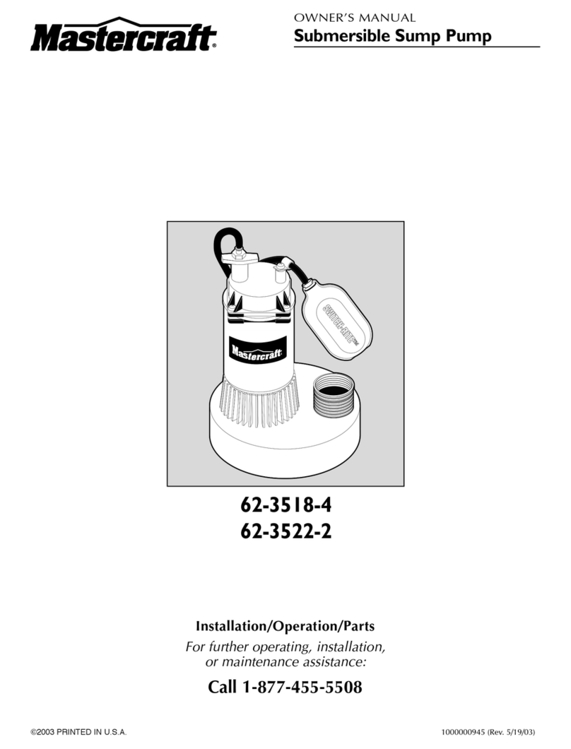
MasterCraft 62-3518-4 User manual

MasterCraft

MasterCraft 62-3518-4 User manual

MasterCraft 062-3422-0 User manual

MasterCraft

MasterCraft 062-3422-0 User manual

MasterCraft 62-3558-8 User manual

MasterCraft

MasterCraft 62-3558-8 User manual

MasterCraft 062-3413-2 User manual

MasterCraft

MasterCraft 062-3413-2 User manual

MasterCraft 062-3415-8 User manual

MasterCraft

MasterCraft 062-3415-8 User manual

MasterCraft 062-3424-6 User manual

MasterCraft

MasterCraft 062-3424-6 User manual

MasterCraft 62-3527-2 User manual

MasterCraft

MasterCraft 62-3527-2 User manual

MasterCraft 62-3520-6 User manual

MasterCraft

MasterCraft 62-3520-6 User manual

MasterCraft 062-3406-0 User manual

MasterCraft

MasterCraft 062-3406-0 User manual

MasterCraft 062-3503-8 User manual

MasterCraft

MasterCraft 062-3503-8 User manual

MasterCraft 62-3515-0 User manual

MasterCraft

MasterCraft 62-3515-0 User manual

MasterCraft 062-3579-8 User manual

MasterCraft

MasterCraft 062-3579-8 User manual

MasterCraft 62-3510-0 User manual

MasterCraft

MasterCraft 62-3510-0 User manual

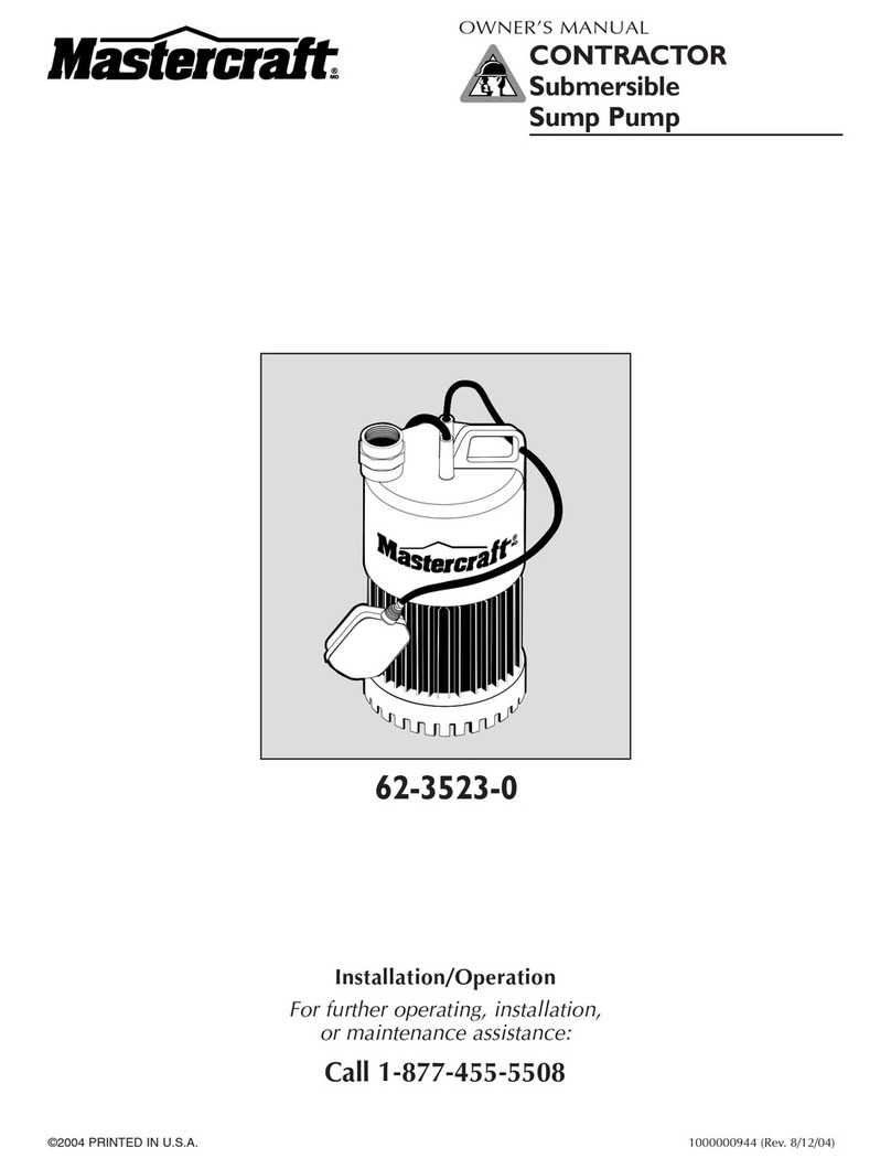
MasterCraft 62-3523-0 User manual

MasterCraft

MasterCraft 62-3523-0 User manual

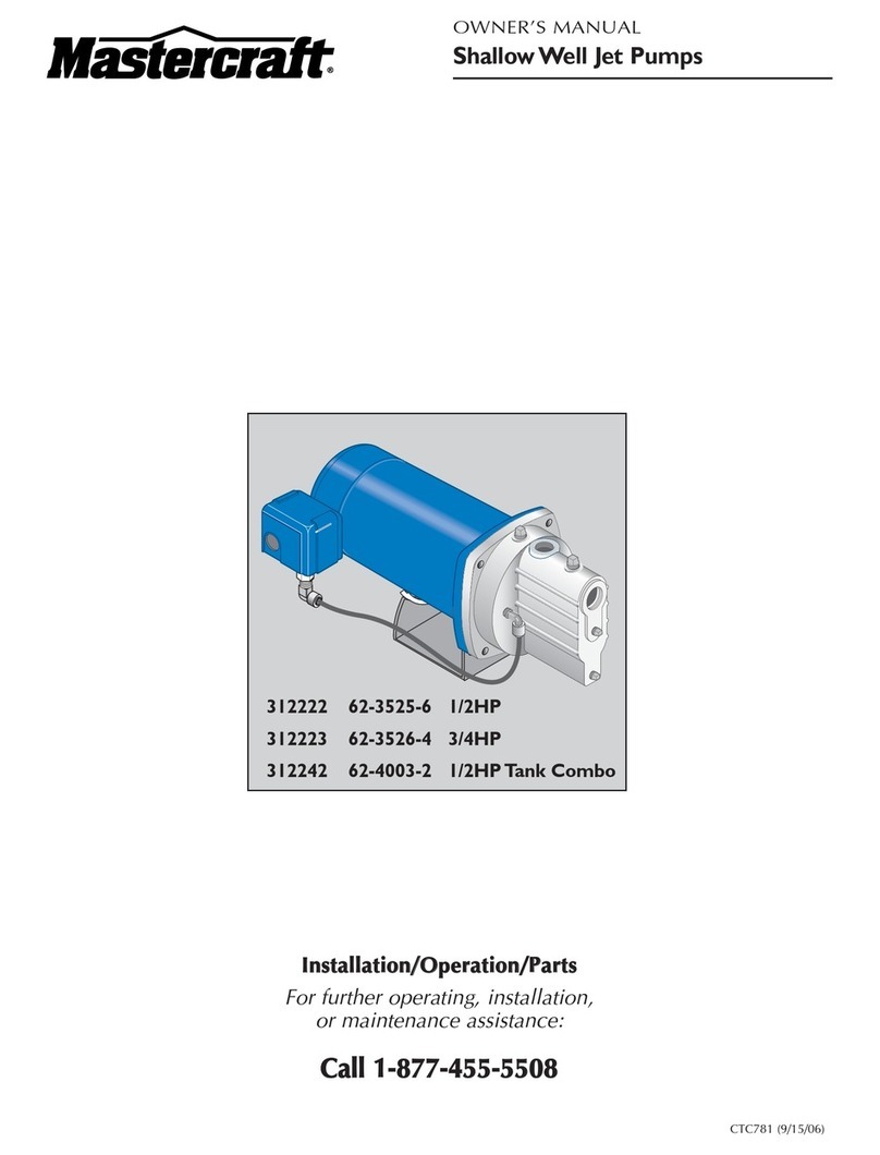
MasterCraft 312222-01 User manual

MasterCraft

MasterCraft 312222-01 User manual

MasterCraft 062-3429-6 User manual

MasterCraft

MasterCraft 062-3429-6 User manual

MasterCraft 062-3408-6 User manual

MasterCraft

MasterCraft 062-3408-6 User manual

MasterCraft 062-3428-8 User manual

MasterCraft

MasterCraft 062-3428-8 User manual

MasterCraft F12V-CTC User manual

MasterCraft

MasterCraft F12V-CTC User manual

MasterCraft 62-3577-2 User manual

MasterCraft

MasterCraft 62-3577-2 User manual

MasterCraft 62-3564-2 User manual

MasterCraft

MasterCraft 62-3564-2 User manual

MasterCraft 062-3404-4 User manual

MasterCraft

MasterCraft 062-3404-4 User manual

MasterCraft 062-3425-4 User manual

MasterCraft

MasterCraft 062-3425-4 User manual

MasterCraft 062-3593-2 User manual

MasterCraft

MasterCraft 062-3593-2 User manual

Popular Water Pump manuals by other brands

Sera ABP-30 operating instructions

Sera

Sera ABP-30 operating instructions

EHEIM 1000 Compact quick guide

EHEIM

EHEIM 1000 Compact quick guide

Homa SaniQ cut instruction manual

Homa

Homa SaniQ cut instruction manual

Jula 733-006 operating instructions

Jula

Jula 733-006 operating instructions

ULTIMATE SPEED 12 V UOP 12 C1 Operation and safety notes

ULTIMATE SPEED

ULTIMATE SPEED 12 V UOP 12 C1 Operation and safety notes

U-Line H-4933 manual

U-Line

U-Line H-4933 manual

Sealey TP6803 instructions

Sealey

Sealey TP6803 instructions

P.I.T. POG900-P1 Operation manual

P.I.T.

P.I.T. POG900-P1 Operation manual

Erbauer ERB422PMP manual

Erbauer

Erbauer ERB422PMP manual

CountyLine CLZT7450 owner's manual

CountyLine

CountyLine CLZT7450 owner's manual

Nordson 100 PLUS FB instruction sheet

Nordson

Nordson 100 PLUS FB instruction sheet

Pfeiffer Vacuum MVP 015 2 operating instructions

Pfeiffer Vacuum

Pfeiffer Vacuum MVP 015 2 operating instructions

Grundfos SMART Digital XL DDA 60-10 Installation and operating instructions

Grundfos

Grundfos SMART Digital XL DDA 60-10 Installation and operating instructions

Ingersoll-Rand PD10X-X-X Operator's manual

Ingersoll-Rand

Ingersoll-Rand PD10X-X-X Operator's manual

Power Craft 79890 instruction manual

Power Craft

Power Craft 79890 instruction manual

Meec tools 015255 operating instructions

Meec tools

Meec tools 015255 operating instructions

EINHELL GC-PW 16 Original operating instructions

EINHELL

EINHELL GC-PW 16 Original operating instructions

ULTIMATE SPEED KH 4256 Original operating instructions

ULTIMATE SPEED

ULTIMATE SPEED KH 4256 Original operating instructions

manuals.online logo
manuals.online logoBrands
  • About & Mission
  • Contact us
  • Privacy Policy
  • Terms and Conditions

Copyright 2025 Manuals.Online. All Rights Reserved.