DMX mode / DMX address settin
1 Ensure the unit is in DMX mode (see above)
2 Press the Up or Down buttons to adjust the DMX address
3 Press the Enter button to confirm the setting
If multiple connected units are to be controlled in exactly the same way, set all units to the same starting address (e.g. 001). If
individual control of multiple connected units is required, each unit must have its own starting address. This address must be at
least 10 channels apart e.g. set the first unit to 001 and the second unit to 011, the third unit to 021 and so on. The DMX
controller will now control all the connected units separately.
Master/Slave mode
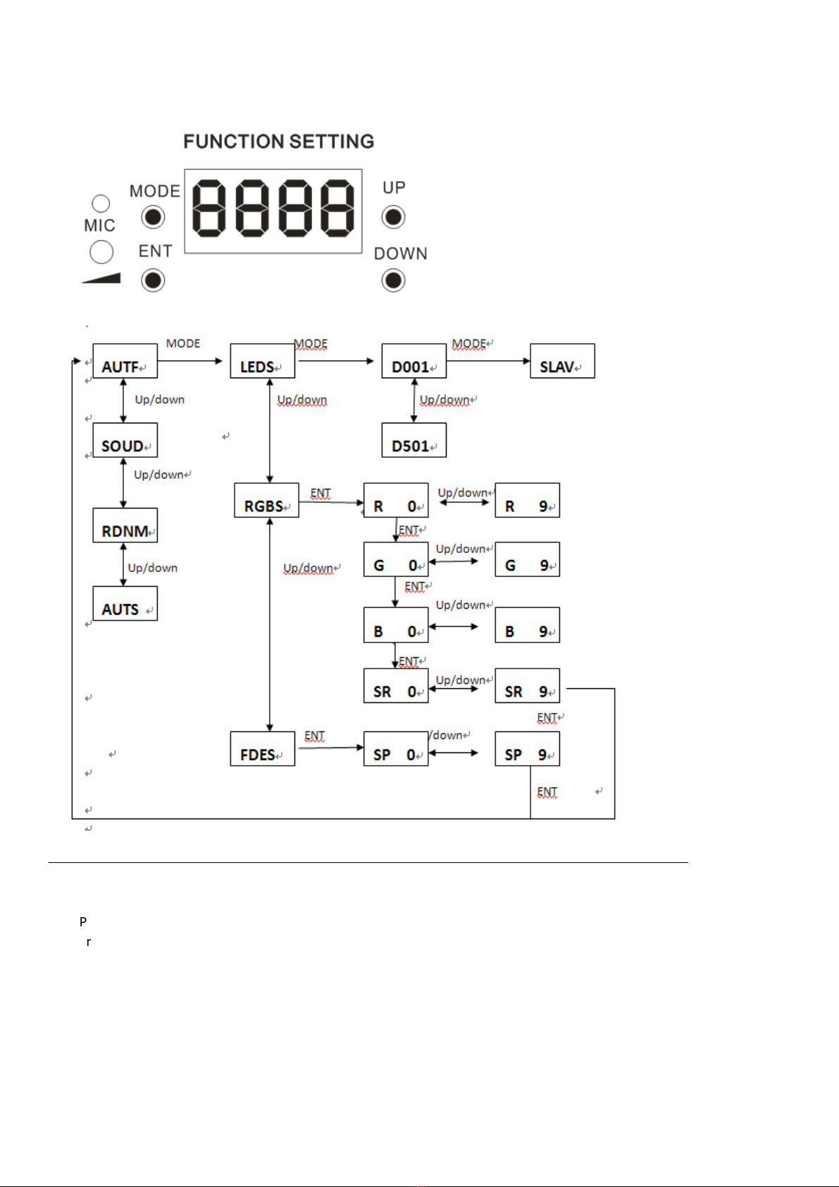
1 Press the function button (MODE) to enter Mode options
2 Press the function button until the LED panel shows SLA
3 Press the Enter button to confirm the setting
The laser will now be working in Slave mode
To create a Master/Slave chain of units, one laser has to be designated as the Master unit whilst the remaining units have to be
set as Slave units. To set the Master unit, choose one laser and set it to your desired mode (Auto mode, Sound-to-Light mode,
etc). Next connect all other units via DMX cables. To achieve this, join the DMX output of one unit to the next unit’s DMX input
until all lasers are connected. Set all the Slave units to Slave mode (see above). The Slave lasers will now duplicate the actions of
the Master unit.
Microphone sensitivity
In sound-activated mode, the sensitivity of the internal microphone can be adjusted via the control panel. To set the sensitivity
level, do the following…
Remote control mode
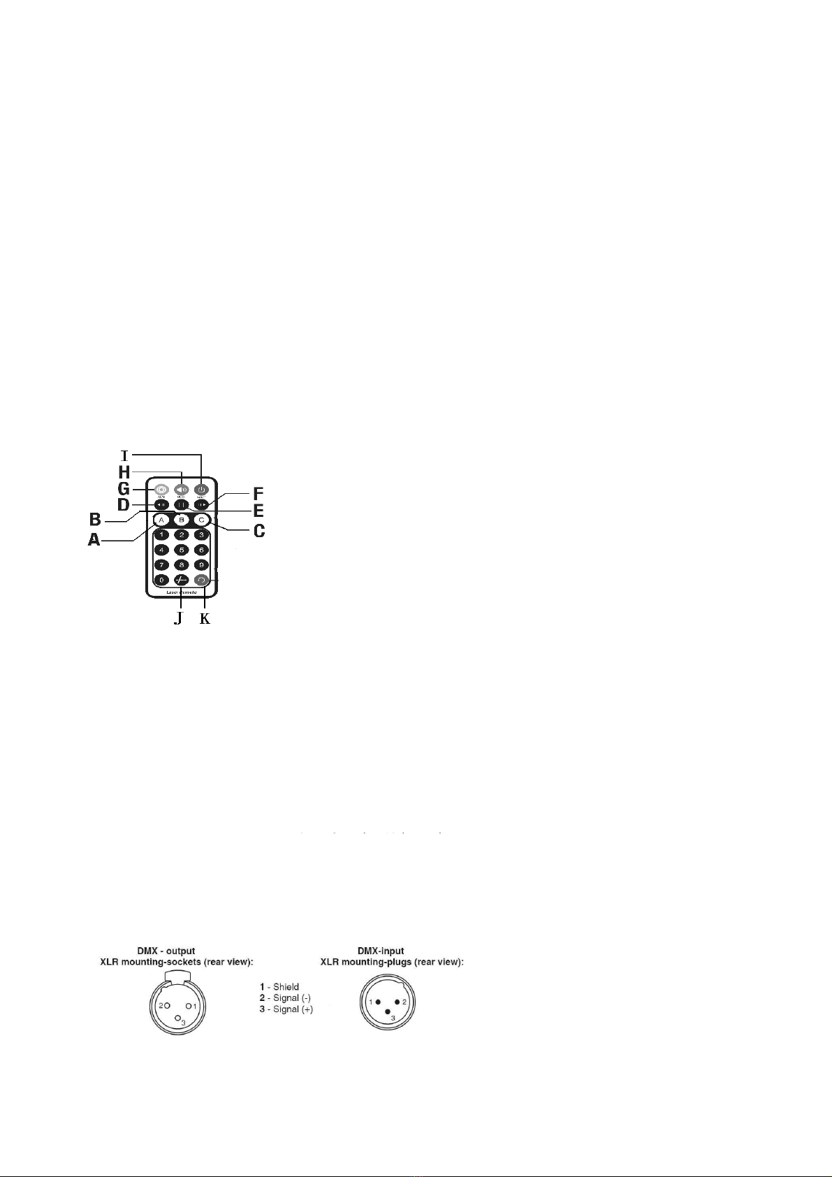
The laser can be operated using the supplied handheld infra-red remote control.
To use this remote control, firstly, remove the plastic tab at the bottom of the remote to activate the internal battery. If
necessary, this can be replaced with a standard CR2025 button cell.
A The A is red laser strobing, use the 0-8 digit buttons to choose strobing speed,0 is close,9 is lighting;
B The B is LED strobing; use the 0-8 digit buttons to choose strobing speed,0 is close;9 is lighting ;
C The C is the speed of the motor; use the 0-9 digit buttons to choose speed,
D/F Color buttons Press buttons to cycle through laser’s/LED’s available color;
E Pause button Press button to pause the laser effect;
G Auto mode Press button to activate Auto mode, First press is AUTO fast,second press is AUTO slow
Music mode Press button to activate Sound-to-Light mode
I On/Off button Press button to activate Sound-to-Light mode
J/K Fruitless Keys;
DMX MODE
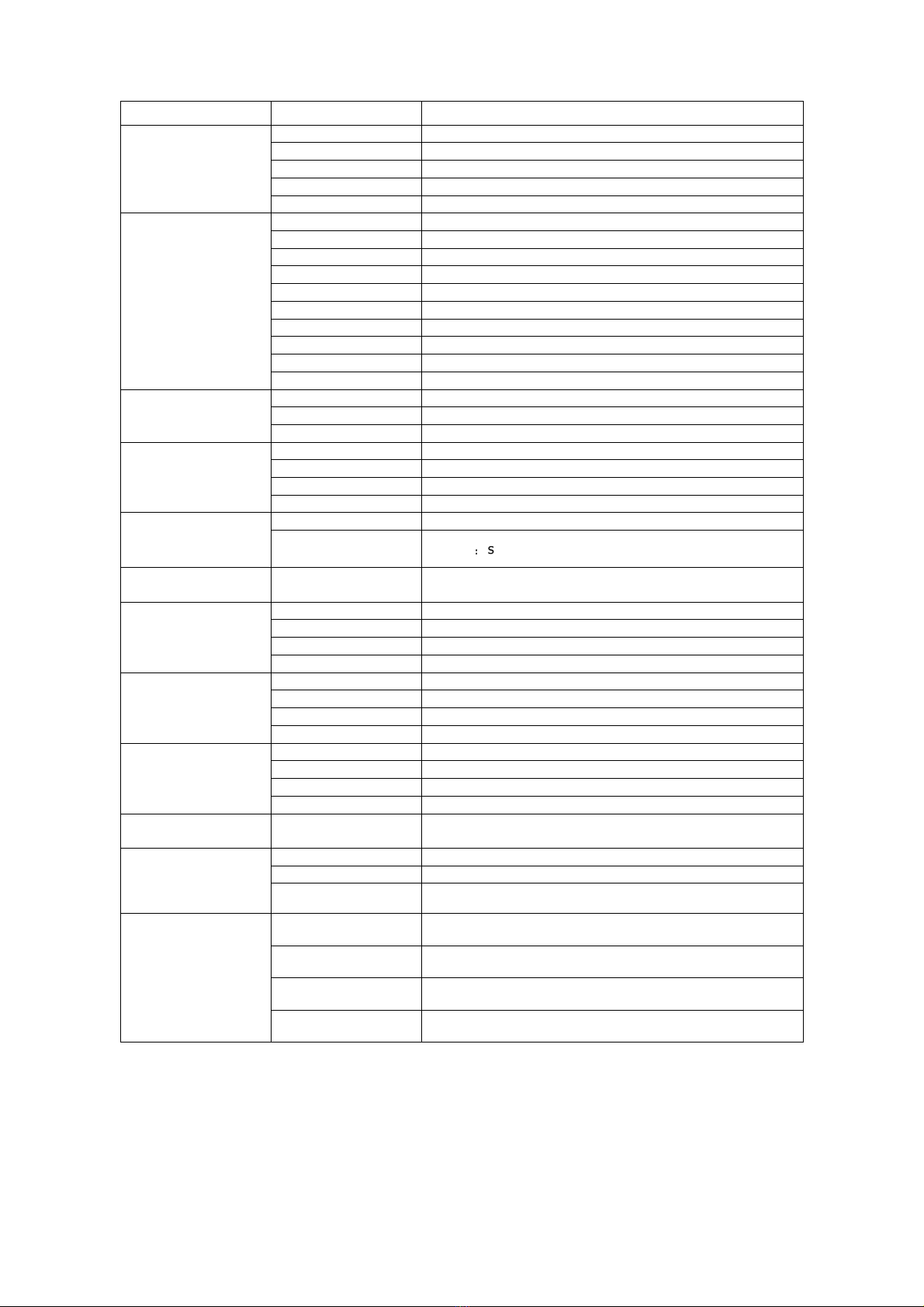
The laser is equipped with 3-pin XLR connectors for DMX input and oThese connectors are wired in parallel. Only use a shielded
twisted-pair cable designed for 3-pin XLR-plugs and connectors in order to connect the controller with the fixture or one fixture
with another.
Caution: At the last fixture, the DMX-cable has to end with a terminator.
Solder a 120 Ohm resistor between PIN 2 (-) and PIN 3 (+) into a 3-pin XLR-plug and plug it in the DMX-output of the last fixture.
turn the laser on and off