Actual product characteristics may vary. Light Culture Australia Pty Ltd reserves the right to improve, modify or update the product designs without prior notice.
–LED Neon must always be used in conjunction with a
certied 24V DC power supply.
–Check the polarity of the connector before inserting the
front connector and switching on the mains power.
–To minimise voltage drop and ensure consistent light
output, position the power supply near to the power
feed end of the LED Neon, and keep the line as short as
possible
–Ensure your maximum run per power feed adheres to the
guidelines; see specication sheet.
–Ensure to add 20% buer when selecting a power supply
–Before making any cuts, installation, maintenance, or
connection, be sure the mains power is disconnected.
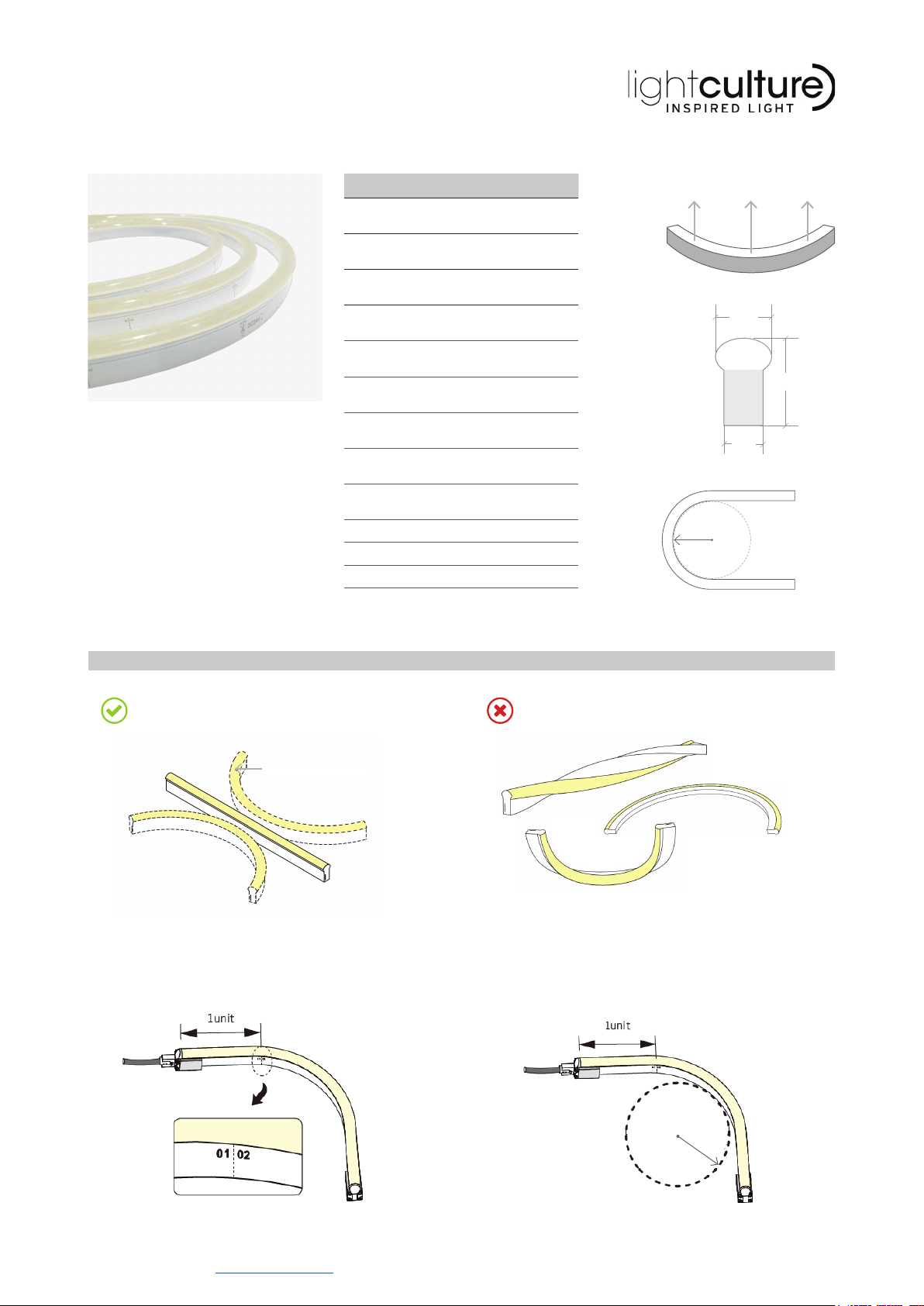
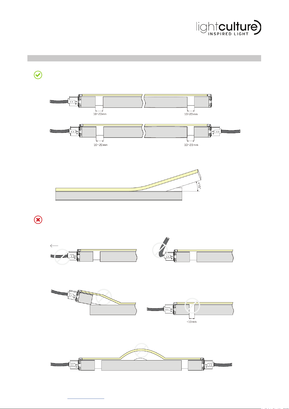
–If essential; cut and connect LED Neon correctly. Any
incorrect operation can cause damage.
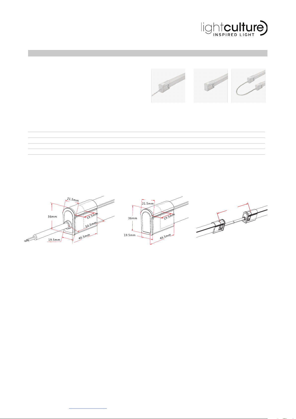
–All connector joints must be connected correctly to
achieve connector IP rating.
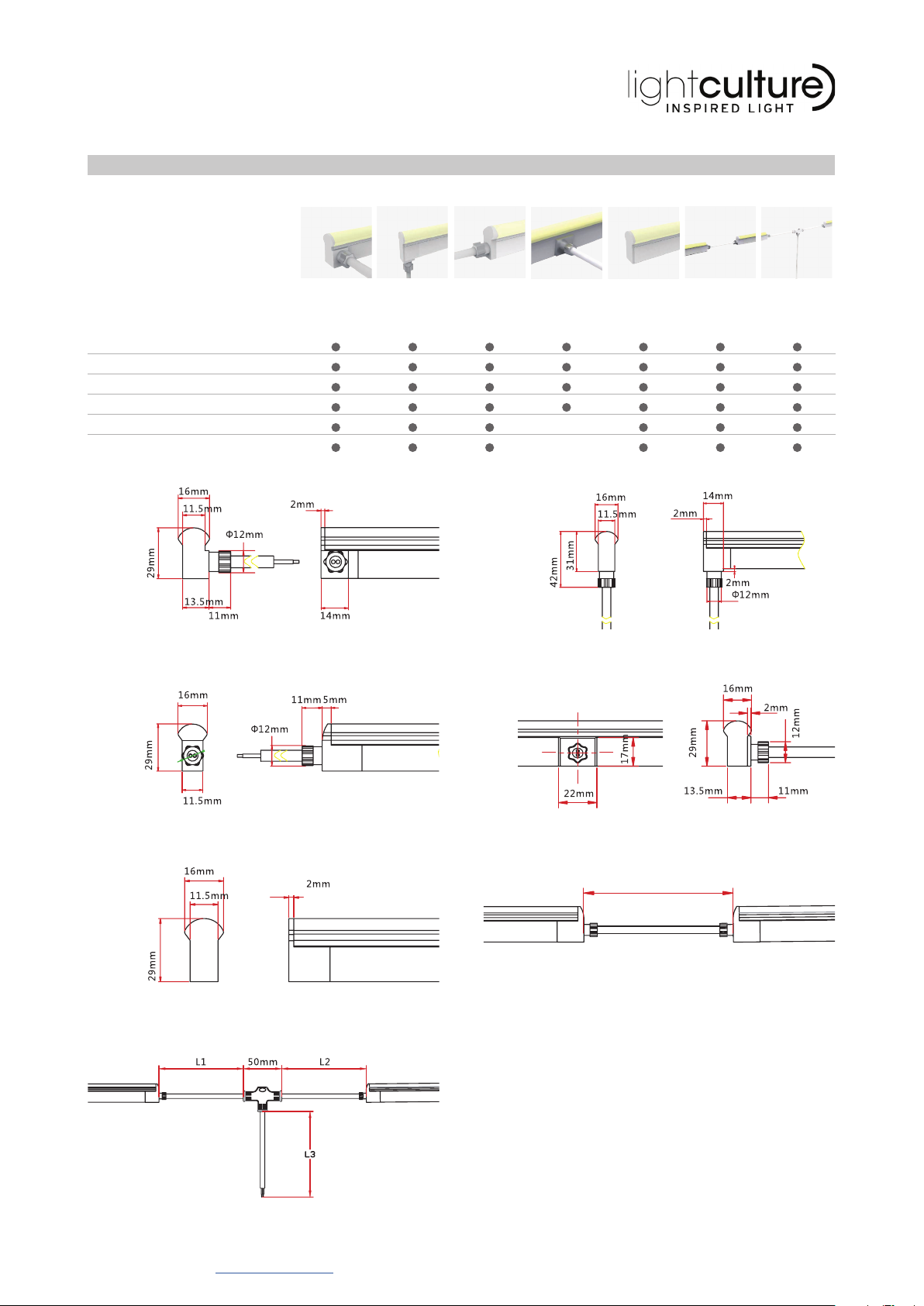
WHITE | SINGLE COLOUR
TUNEABLE WHITE
RGB
RGBW
DYNAMIC RGB ‘CHASING’
DMX OPTION AVAILABLE
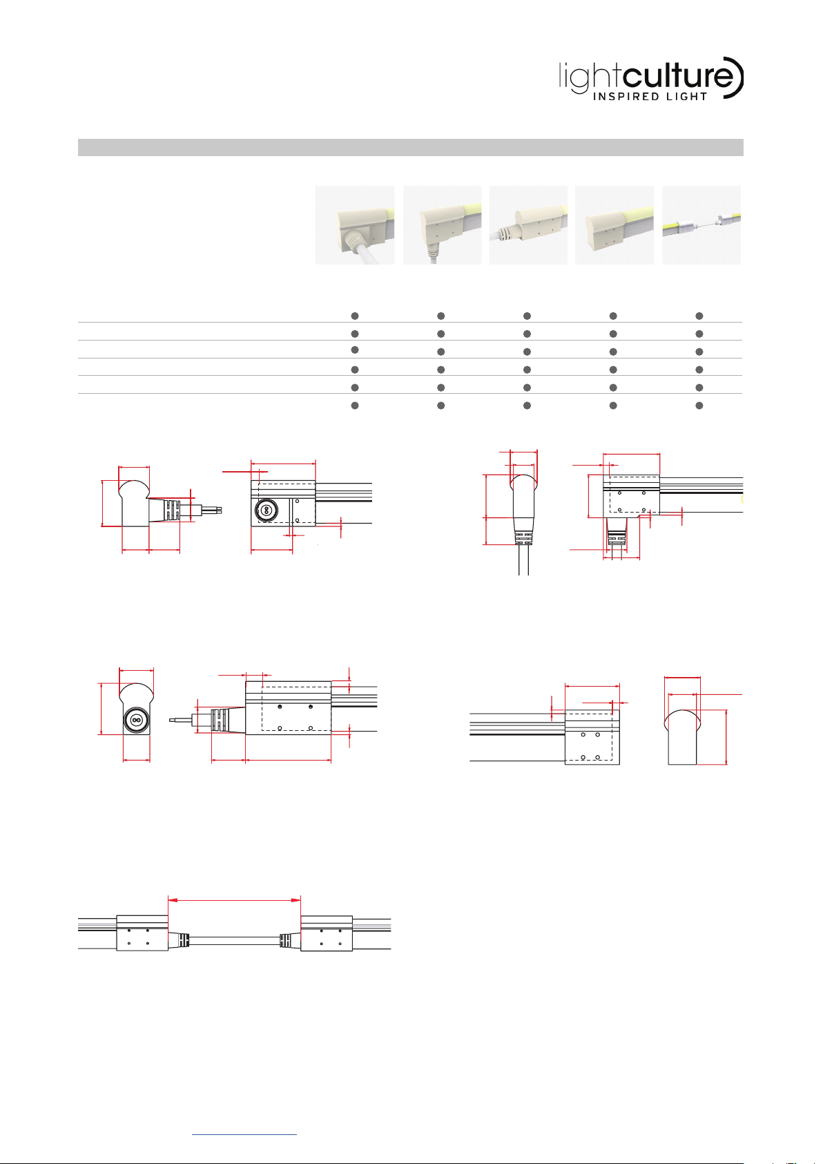
NEON CLASSIC | ELECTRICAL AND PHYSICAL INSTALLATION GUIDE
WIRING DIAGRAMS
POWER SUPPLY RGB CONTROL
green wire: “G” terminal (-)
blue wire: “B” terminal (-)
yellow wire: +
red wire: “R” terminal (-)
24V DC
POWER SUPPLY 2-CHANNEL
CONTROL
black wire: Cool White connection (-)
red wire: +
yellow wire: Warm White connection (-)
24V DC
POWER SUPPLY RGBW CONTROL
green wire: “G” terminal (-)
blue wire: “B” terminal (-)
white wire: “W” terminal (-)
yellow wire: +
red wire: “R” terminal (-)
24V DC
POWER SUPPLY DIMMER
optional black wire: -
red wire: +
24V DC
black wire: “GND”, Cathode (-) terminal
red wire: “VCC”, Anode (+) terminal
yellow wire: “Signal” terminal
POWER SUPPLY INDEPENDENT
SPI CONTROL
24V DC