Actual product characteristics may vary
www.lightculture.com.au
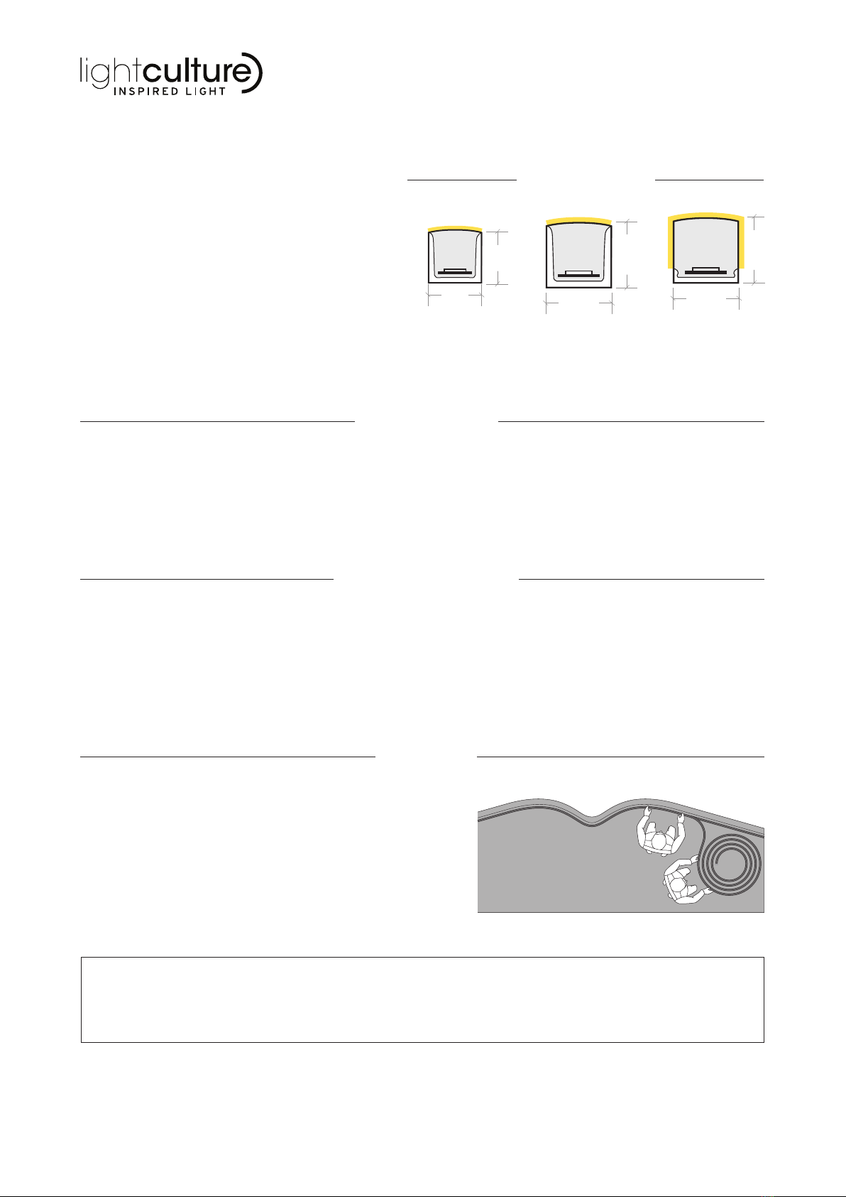
NEON MICRO Y NEON Y NEON Y3
HANDLING
GENERAL INFO
ELECTRICAL SAFETY
NEON Y MODELS
NEON Y | INSTALLATION INTRO
16.5
16.5
13.5
13.5
16.5
16.5
1/8
This installation guide is for Neon Y, Neon Micro Y &
Neon Y3. LED Neon Y is a vertical bending and highly
durable linear LED product suitable for both indoor and
outdoor applications. This installation guide is divided
into four sections:
-INTRO
- CORES & WIRE CONNECTION REFERENCE
(wiring diagrams on specication sheets)
- PRODUCT PHYSICAL PARAMETERS
- INSTALLATION & MOUNTING
This user manual is intended to cover as much detail as possible for this product, and great care has been taken to ensure this and the accuracy of
the information contained within, however should additional information or clarication be required that is not covered within this manual or associated
data sheets, or if there are any uncertainties regarding the installation and operation of this product, Distributor MUST be contacted before any work is
carried out on the xture or associated products.
LED Neon must be installed by at least 2 people, who can support the
product in various locations as shown. During installation, care should
be taken to ensure the bending radius of is not exceeded.
When transporting the product, it is advisable to use the original
packaging in which the product left the factory.
Do not roll out the product onto rough surfaces or over sharp corners.
This will scratch the PVC optics and damage the finish of the product.
Do not power the product whilst in packaging.
Note: Other models may have different parameters,ensure
you have the correct installation guide for your model.
FAILURE TO COMPLY WITH THIS MANUAL AND LOCAL ELECTRICAL AND CONSTRUCTION REGULATIONS MAY RESULT IN SERIOUS INJURY
OR EVEN DEATH - ALWAYS ISOLATE POWER BEFORE WORKING ON ELECTRICAL PRODUCTS AND ENSURE ADEQUATE MEASURES ARE
TAKEN TO MECHANICALLY SUPPORT FIXTURES AT ALL TIMES.
- This product must be installed by a qualied
and competent professional.
- Always disconnect the power supply before
attempting to maintain or service the
equipment.
- Do not work on the product with wet hands.
- Make sure that all parts of the equipment are
kept clean and free of dust which should be
carried out as part of a maintenance cycle
that’s appropriate for the installation location
of the product.
- The lamp (LED) should be changed if it has
become damaged or thermally deformed.
- Do not power the product if :
- The outer PVC jacket is damaged
- There are loose electrical connections
- The wires are visible without insulation.
- Do not stare directly into the LED light
source.
- Always disconnect the power supply before
attempting to maintain or service the
equipment.
- The Earth wire MUST ALWAYS be
connected.
- Local electrical and building regulations must
be followed.
- Do not power the product whilst in
packaging.
- Always make sure that the power and data
connections are connected correctly and
securely.
- The power supply (PSU), DMX/RDM driver
and LED drivers should be changed if they
fail to operate.
- Do not cut while the LED ex neon is
connected to power.
- Do not reverse polarity when connecting
from both ends. This will damage the internal
PCB. Always test connections with a multi-
meter before applying power.
- Must always be used with an electrical
isolation transformer providing SELV (safety
extra low voltage).


