Lightspeed Delta X6 User manual

User Manual
Classroom Audio System
Delta X6


TABLE OF CONTENTS
SECTION 1: 4 System Components and Unpacking
Overview 5 Optional Components
6 Quick Start Guide
9 Top Panel Wireless Receiver Controls
10 Top Panel Controls & Connections
11 Rear Panel Controls & Connections
12 Installing or Replacing Receiver Module
SECTION 2: 14 Step 1. Connecting the Delta X6 Receiver to a
Power Supply
Set-up & Use 15 Step 2A. Setting up one DeltaX6 Receiver
16 Step 2B. Using More Than One Delta X6
Receiver
HANDHELD TRANSMITTER
17 Step 3. Channel Selection
18 Step 4. Mute & Sensitivity Levels
19 Step 5. Battery Life Indicator & Battery Type
20 Step 6. Replacing Batteries
21 Step 7. Recharging Batteries
BELT-PACK TRANSMITTER
22 Step 8. Connecting and Placing
23 Step 9. Channel Selection
24 Step 10. Mute and Gain Adjustment
25 Step 11. Battery Life Indicator and Type
26 Step 12. Replacing Batteries
27 Step 13. Recharging Batteries
28 Quick Start User’s Guide
29 Daily Use Instructions
SECTION 3: 30 Hand Held Microphone
Optional Accessories 31 Belt-Pack Transmitter
SECTION 4: 32 Troubleshooting Guide
Troubleshooting
SECTION 5: 34 Warranty Statement
Warranty &
Specifications
36 Safety Instructions & Warnings
37 System Specifications

4
1. Overview 2. Setup & Use 3. Optional
Accessories 4. Troubleshooting 5. Warranty, Safety
& Specifications
SECTION 1:
OVERVIEW
SYSTEM COMPONENTS AND UNPACKING
The standard configuration of the Delta X6™ will contain:
Delta X6 Carry Case
Delta X6 Public
Address System
and Power Supply
HM-900 Transmitter

5
1. Overview 2. Setup & Use 3. Optional
Accessories 4. Troublshooting 5. Warranty, Safety
& Specifications
OPTIONAL COMPONENTS
Optional equipment which may be part of your Delta X6 system:
Individual Components
RX-7100R 100 Channel UHF Receiver Module
TX-HM900 100 Channel UHF Handheld Transmitter
AC-MH7 Mic Clip for HM900 Handheld Transmitter
TX-BP900 100 Channel UHF Belt-Pack Transmitter
BC-TX900 Battery Charger for BP900 or HM900
MC831S Audio-Technica 831 Lapel Mic
MC-TK270S Lightspeed Noise-cancelling Headset Mic
PS-15V-4.3 AC Power Supply
BA-NH1 AA NiMH Rechargeable Battery
AC-SPDELTA-X6 Carry Bag for Delta X6
AC-831CLIP Mic clip for MC-831S
AC-PWR-NA AC North American Power Cable
Optional Accessories
CA-GTC900 Guitar/aux In Cable for BP900
AC-TWBRK Speaker Stand Bracket
AC-SS1 Tripod Speaker Stand
AC-SPSS1 Carry Bag for Tripod Speaker Stand
MC-H10 Wired Dynamic Handheld Mic
BP-900 Transmitter and
Charger
MK-TK270S Noise-
Cancelling Headset
Microphone
MC-831S Audio
-Technica 831 Lapel
Mic

6
1. Overview 2. Setup & Use 3. Optional
Accessories 4. Troubleshooting 5. Warranty, Safety
& Specifications
LightSPEED
7100R
UHF TRUE
DIVERSITY
RECEIVER
A B
LOW
BAT SCAN SQ
RF
CHANNEL
LCD
Display
QUICK START GUIDE
System Overview
1. System Setup
Amplified
Audio Out
UHF Receiver
Module
LightSPEED
7100R
UHF TRUE
DIVERSITY
RECEIVER
A B
LOW
BAT SCAN SQ
RF
CHANNEL
Use Scan
Button
to Select
Channel
Power Overview
LOW
BAT
LOW
BAT
Turn ON Power/
Wireless Mic 1
Volume Knob

7
1. Overview 2. Setup & Use 3. Optional
Accessories 4. Troublshooting 5. Warranty, Safety
& Specifications
QUICK START GUIDE CONT’D
2. Handheld Transmitter Setup
• Press and hold POWER to turn on.
• To set channel, press and hold SET
until cursor blinks on LCD display
(approximately 3 seconds).
• Use UP and DOWN to change
channel number.
• Press and hold SET to save
selected channel.
PWR
DN UP
PWR
D
NU
P
POWER
LCD Display
SET
UPDOWN
3. Belt-pack Transmitter Setup
• Press and hold ON for power.
• Open the plastic door by
depressing latches on each side.
• To set channel, press and hold SET
until cursor blinks on LCD display
(approximately 3 seconds).
• Use UP and DOWN to change
channel number.
• Press and hold SET to save
selected channel.
• Attach microphone into Mic Jack.
Belt Clip
LCD
Display
Mic Jack
On/Off
Button
Mute Switch
Red LED
CH: 002
CH: 002
694.500M
LS
HM-900
SENS SET
LEVEL [2]
NiMH
AKLN
CH: 002
CH: 002
694.500M
LS
HM-900
SENS SET
LEVEL [2]
NiMH
AKLN
CH: 002
CH: 002
694.500M
LS
HM-900
SENS SET
LEVEL [2]
NiMH
AKLN
CH: 002
CH: 002
694.500M
LS
HM-900
SENS SET
LEVEL [2]
NiMH
AKLN
Gain
Adjust
Door
Latch
Toggle
DOWN
Toggle
UP
Set

8
1. Overview 2. Setup & Use 3. Optional
Accessories 4. Troubleshooting 5. Warranty, Safety
& Specifications
QUICK START USER’S GUIDE CONT’D
5. Final System Adjustment
• If your system contains
two wireless receivers and
microphones, do the following:
• Leave the first transmitter ON.
• Press SCAN on the second
receiver (Wireless Mic 2).
• Go to Steps 2 and 3 to program
the second transmitter.
WM 1 = Wireless Mic 1
WM 2 = Wireless Mic 2
LOW
BAT
LOW
BAT
RF Light indicates both
receiver module and
transmitter(s) are on
LightSPEED
7100R
UHF TRUE
DIVERSITY
RECEIVER
A B
LOW
BAT SCAN SQ
RF
CHANNEL
LCD
Display
4. Wired Microphone Setup Use AUX IN/MIC
IN to Control
Volume
LOW
BAT
LOW
BAT
MIC IN
Transmitter Location During Use
Do not stand directly in front of the
DELTA X6 with the microphone on.
Avoid!

9
1. Overview 2. Setup & Use 3. Optional
Accessories 4. Troublshooting 5. Warranty, Safety
& Specifications
LOW
BAT
LOW
BAT
LOW
BAT
LOW
BAT
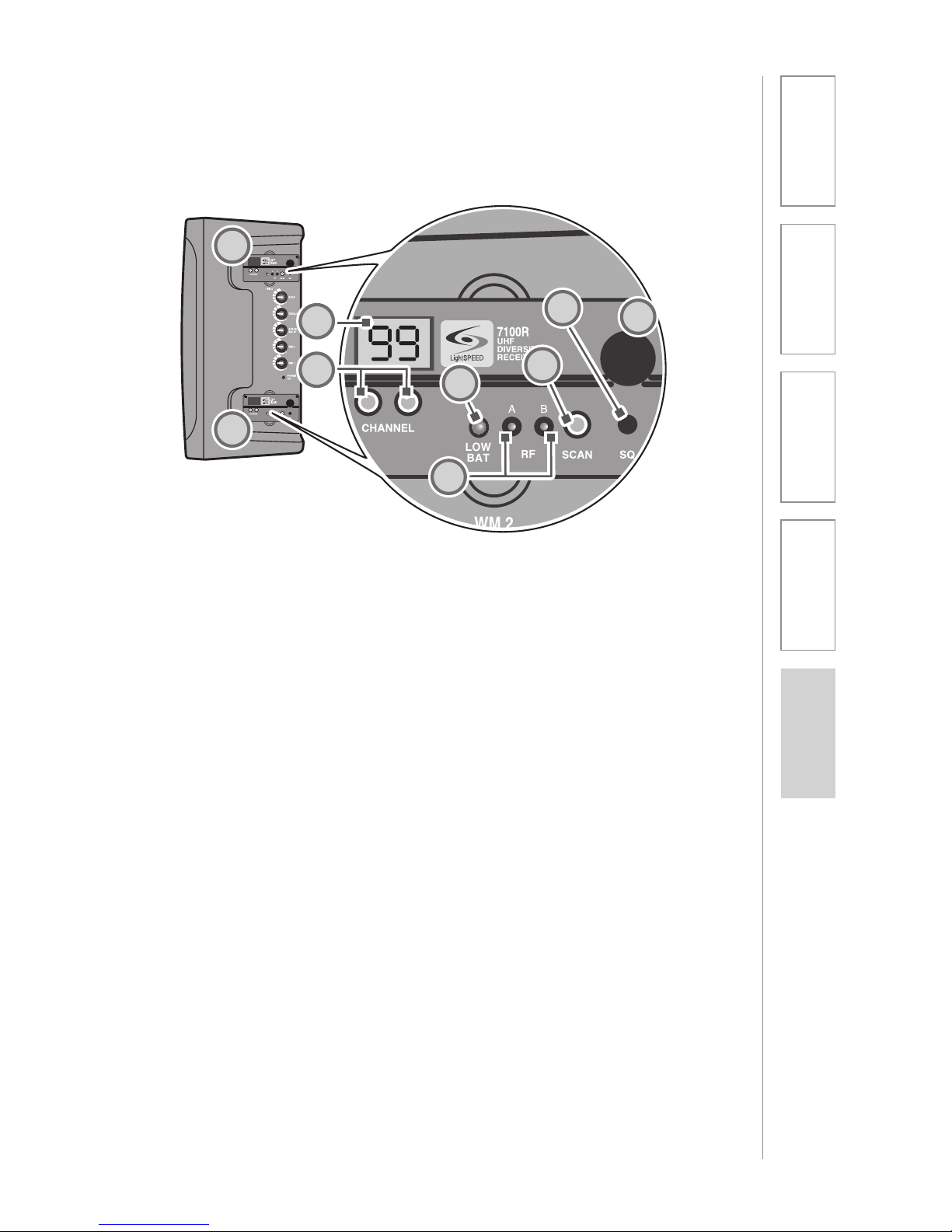
TOP PANEL: WIRELESS RECEIVER CONTROLS
5. TRANSMITTER LOW BATTERY
INDICATOR: This LED will light
to indicate the batteries in the
corresponding transmitter are low.
6. SCAN: Press this button to auto-
matically select a channel that is
free from interference.
7. SQUELCH LEVEL ADJUSTMENT:
Covered with a plastic cap, the
squelch is adjusted at the factory
to provide the best signal level
and minimum noise. There is no
need to adjust the squelch level in
the field.
8. RECEIVER POWER/VOLUME
ADJUSTMENT: The receiver
volume adjustment is covered
with a plastic cap. The volume is
adjusted at the factory to provide
the best signal level and minimum
noise. There is no need to adjust
the receiver volume in the field.
1. WIRELESS RECEIVER: One or
two wireless receiver modules are
located at the top panel.
2. CHANNEL DISPLAY: An LED
readout of the receiver module
indicates which channel you are on.
3. CHANNEL CONTROL (0-99): The
left button controls the number
on the left (0-9). Each touch of
the button moves the number up
one until it gets to nine, and then
it cycles back to zero. The right
button has the same function for
the number on the right.
4. RF CHANNEL A/B INDICATOR:
The A lights up indicating the
A channel tuner is receiving the
strongest RF signal. The B lights
up indicating the B channel tuner
is receiving the strongest RF
signal.
1
1
2
36
5
78
4

10
1. Overview 2. Setup & Use 3. Optional
Accessories 4. Troubleshooting 5. Warranty, Safety
& Specifications
TOP PANEL CONTROLS AND
CONNECTIONS
1. BASS: Controls the level of low
frequency sound output for the
system.
2. TREBLE: Controls the level of high
frequency sound output for the
system.
NOTE: Reducing Feedback
The BASS and TREBLE controls
can be used to reduce feedback
(“squealing” or “howling”). If you
hear high-pitched squealing, lower
the treble setting. If you hear low-
pitched howling, lower the bass
setting.
3. AUX IN/MIC IN: Controls the
volume of a wired microphone
plugged into MIC IN on the back
of the system and the volume of
an auxiliary piece of equipment
plugged into the AUX IN on the
back of the system.
4. WIRELESS MIC 2: Controls the
volume of Wireless Microphone 2
(WM2) if a second wireless receiver
is installed.
5. POWER/WIRELESS MIC 1: Turn
this knob clockwise to power up
the system. Rotate to adjust the
volume of Wireless Microphone 1
(WM1).
6. POWER LED: Glows GREEN when
the system is powered on..
1
2
3
6
5
4
LOW
BAT
LOW
BAT

11
1. Overview 2. Setup & Use 3. Optional
Accessories 4. Troublshooting 5. Warranty, Safety
& Specifications
1
2
3
5
4
REAR PANEL CONTROLS AND CONNECTIONS
5. AUX OUT: This ¼” jack provides a
line level output signal that can be
connected to a recorder, assistive
listening device, etc.
6. SPEAKER OUT (SWITCHED): This
¼” jack can be used to connect
to an external passive speaker.
[NOTE: connection to this jack will
mute the internal speaker of the
Delta X6.]
7. FUSE: The fuse holder is
accessible using a flat-blade
screwdriver. Push in and rotate ¼
turn counterclockwise to remove.
[NOTE: replacement is a 4A 250V
fuse.]
8. DC POWER: This jack provides a
connection for the Delta X6 power
supply.
1. MIC IN: This ¼” jack provides
an input for a wired handheld
microphone.
2. AUX IN: This 3.5 mm jack provides
an input for audio from an external
device, such as a CD player, MP3
player, TV/VCR, computer, etc.
[NOTE: the Delta X6 does not
output in stereo; only one channel
of the input mix will be heard.]
3. AUX OUT: This 3.5 mm jack
provides an adjustable-level audio
output that can be connected to
a recorder or assistive listening
device.
4. AUX OUT VOLUME: This knob
controls the level of the 3.5 mm
AUX OUT jack. Counterclockwise
represents a microphone level
signal, while fully clockwise
represents a line level signal.
6
7
8

12
1. Overview 2. Setup & Use 3. Optional
Accessories 4. Troubleshooting 5. Warranty, Safety
& Specifications
INSTALLING OR REPLACING A RECEIVER
MODULE
NOTE: Make sure the Delta X6 is
turned off.
1. Remove the two screws securing
the module panel using a small
phillips head screwdriver.
2. Remove the module from the
enclosure by carefully inserting
the blade of a small, flat-blade
screwdriver under the face plate
edge and nudging it upward.
3. Grasp the edges of the module
with both hands and slide
it out.
4. Install the new module by aligning
it with the guide rails and sliding
all the way in to engage the
connector at the rear of the
module.
5. Replace the two screws.
LOW
BAT
LOW
BAT

13
1. Overview 2. Setup & Use 3. Optional
Accessories 4. Troublshooting 5. Warranty, Safety
& Specifications

14
1. Overview 2. Setup & Use 3. Optional
Accessories 4. Troubleshooting 5. Warranty, Safety
& Specifications
SECTION 2:
SET-UP & USE
1. CONNECTING THE DELTA X6 RECEIVER
TO A POWER SUPPLY
1. Locate the power supply.
2. Insert the DC connector into the
“POWER INPUT” connector on the
bottom of the Delta X6 and plug
the other end to an electrical
outlet.
3. Turn the POWER/WIRELESS MIC1
knob clockwise to turn the system
on.
4. The GREEN LED light next to the
knob will illuminate to confirm the
system is powered up.
LOW
BAT
LOW
BAT
LOW
BAT
LOW
BAT

15
1. Overview 2. Setup & Use 3. Optional
Accessories 4. Troublshooting 5. Warranty, Safety
& Specifications
2A. SETTING UP ONE DELTA X6 RECEIVER
1. Turn the Delta X6 ON by rotating
the WM1 knob clockwise. The
GREEN LED will light.
Channel Selection: Receiver
Each Receiver has 100 user-selectable
channels to choose from. You can
either select a channel manually or by
pressing the SCAN button, which will
automatically select a clear channel.
2. When the system is switched on,
the receiver will have two letters
flashing on the screen to indicate
the corresponding frequency
group.
3. Clear Channel SCAN (recomm-
ended):
A) Make sure the transmitter(s) is
OFF before pressing this button.
When this button is pressed, the
receiver will cycle through all
100 channels and select a clear
frequency. (This process takes
about 20 seconds.)
B) Once the receiver selects the
clear channel, you will need to
select the same channel on the
corresponding transmitter
(handheld or belt-pack). See pages
11 and 16 for instructions.
NOTE There are 3 different groupings
of 100 channels available. When
the system is powered ON, the
two letters that initially blink in the
channel window on the receiver
indicate the frequency group (see
chart on page 25 for further details).
LOW
BAT
LOW
BAT
LOW
BAT
LOW
BAT
LightSPEED
7100R
UHF TRUE
DIVERSITY
RECEIVER
A B
LOW
BAT SCAN SQ
RF
CHANNEL
LightSPEED
7100R
UHF TRUE
DIVERSITY
RECEIVER
A B
LOW
BAT SCAN SQ
RF
CHANNEL
LightSPEED
7100R
UHF TRUE
DIVERSITY
RECEIVER
A B
LOW
BAT SCAN SQ
RF
CHANNEL

16
1. Overview 2. Setup & Use 3. Optional
Accessories 4. Troubleshooting 5. Warranty, Safety
& Specifications
2B. USING MORE THAN ONE DELTA X6
RECEIVER
If you have a second receiver:
A) Verify that Wireless Mic 1
transmitter and receiver are ON
and set to the same clear channel.
B) Make sure the transmitter for
Wireless Mic 2 is turned OFF.
C) Press the SCAN button on the
Wireless Mic 2 receiver.
D) After the Wireless Mic 2 receiver
selects a clear channel, set
the Wireless Mic 2 transmitter
(handheld or belt-pack) to the
elected channel. See pages 11 and
16 for instructions.
3. Manual Channel Selection:
A) Pressing the left CHANNEL
button changes the first number
(0-9).
B) Pressing the right CHANNEL
button changes the second
number (0-9).
C) Once a frequency is selected,
you will need to select the same
channel on the corresponding
transmitter (handheld or belt-
pack). See pages 11 and 16 for
instructions.
LightSPEED
7100R
UHF TRUE
DIVERSITY
RECEIVER
A B
LOW
BAT SCAN SQ
RF
CHANNEL

17
1. Overview 2. Setup & Use 3. Optional
Accessories 4. Troublshooting 5. Warranty, Safety
& Specifications
3. CHANNEL SELECTION: HANDHELD
TRANSMITTER
Once a channel has been selected on
the receiver, you now need to select
that same channel on the handheld
transmitter. If you have a belt-pack
transmitter, go to page 18 for channel
selection instructions.
1. Turn on the microphone by holding
the power button on the bottom
of the barrel for approximately two
seconds.
2. Use the UP and DN buttons to
select a screen that shows the
current channel.
3. To change the channel, press and
hold the SET button for about 3
seconds until there is a blinking
cursor on the LCD display window.
4. Use the UP and DN buttons to set
the channel to match the receiver.
5. Press and hold the SET button for
about 3 seconds again until the
blinking cursor disappears and the
RED LED flashes.
NOTE: To read the frequency in MHz,
press UP once.
Transmitters and receivers are
available in 3 different frequency
groups. Verify that the letter code
that blinks on the receiver (when
powered ON) matches the letter code
on the silver sticker in the battery
compartment of the transmitter.
LightSPEED
7100R
UHF TRUE
DIVERSITY
RECEIVER
A B
LOW
BAT SCAN SQ
RF
CHANNEL
Model Number: HM900
Serial Number
HM90014324024
FREQUENCY L-670 MADE IN TAIWAN
PWR
DN UP
PWR
D
NU
P
PWR
DN UP
PWR
D
NU
P
PWR
DN UP
PWR
D
NU
P
CH: 002
CH: 002
694.500M
LS
HM-900
SENS SET
LEVEL [2]
NiMH
AKLN
Turn ON
Use UP and
DN to scroll
through screens
until channel is
displayed
Use SET button
to change
and save
new channel
selection

18
1. Overview 2. Setup & Use 3. Optional
Accessories 4. Troubleshooting 5. Warranty, Safety
& Specifications
4. MUTE AND SENSITIVITY LEVELS ON
HANDHELD MICROPHONE
PWR
DN UP
PWR
D
NU
P
PWR
DN UP
PWR
D
NU
P
PWR
DN UP
PWR
D
NU
P
PWR
DN UP
PWR
D
NU
P
3X
CH: 002
CH: 002
694.500M
LS
HM-900
SENS SET
LEVEL [2]
NiMH
AKLN
CH: 002
CH: 002
694.500M
LS
HM-900
SENS SET
LEVEL [2]
NiMH
AKLN
CH: 002
CH: 002
694.500M
LS
HM-900
SENS SET
LEVEL [2]
NiMH
AKLN
CH: 002
CH: 002
694.500M
LS
HM-900
SENS SET
LEVEL [2]
NiMH
AKLN
4
4
Transmitter Mute
The mute switch turns the
transmitter’s audio signal ON and
OFF. The audio is muted when the
RED LED is flashing.
Sensitivity Level
This function allows the user to set
the gain structure of the microphone
to best fit the voice level of the
person speaking into it. A person
with a very loud, booming voice may
want the microphone set to sensitivity
level of 1 or 2. A person with a very
soft voice will be better off with the
microphone set to a sensitivity 3 or 4.
To change the sensitivity setting:
1. Press the UP button 3 times to get
to the Sensitivity Level screen.
2. Press and hold the SET button until
a blinking cursor appears.
3. Use the UP and DN buttons to
make a selection (1-4).
4. Press and hold SET until the
blinking cursor disappears.

19
1. Overview 2. Setup & Use 3. Optional
Accessories 4. Troublshooting 5. Warranty, Safety
& Specifications
5. BATTERY LIFE INDICATOR AND BATTERY-
TYPE ON HANDHELD MICROPHONE
Battery Life Indicator
The battery life is shown on the
primary screen of the LCD. The 7-step
fuel gauge acts as a detailed guide to
show the actual life of the battery.
Battery Type
The transmitter will operate with
either standard AA alkaline batteries
or nickel metal hydride (NiMH)
rechargeable batteries. Since these
types of batteries have different
characteristics, it is important to set
the transmitter to the appropriate
type of battery being used so that
the Battery Life Indicator will operate
properly.
To change the Battery Type setting:
1. Press the UP button 2 times to get
to the Battery Type screen.
2. Press and hold the SET button until
a blinking cursor appears.
3. Use the UP and DN buttons to
make a selection.
4. Press and hold SET until the
blinking cursor disappears.
PWR
DN UP
PW
R
D
NU
P
PWR
DN UP
PWR
D
NUP
PWR
DN UP
PWR
D
NU
P
PWR
DN UP
PWR
D
NU
P
CH: 002
CH: 002
694.500M
LS
HM-900
SENS SET
LEVEL [2]
NiMH
AKLN
2X
CH: 002
CH: 002
694.500M
LS
HM-900
SENS SET
LEVEL [2]
NiMH
AKLN
CH: 002
CH: 002
694.500M
LS
HM-900
SENS SET
LEVEL [2]
NiMH
AKLN
CH: 002
CH: 002
694.500M
LS
HM-900
SENS SET
LEVEL [2]
NiMH
AKLN
CH: 002
CH: 002
694.500M
LS
HM-900
SENS SET
LEVEL [2]
NiMH
AKLN
NOTE: Do not mix battery types.
WARNING: Do not use NiCad
batteries! They will not charge
properly and may cause damage to
the transmitter.
Lightspeed recommends Panasonic
or Energizer batteries. Duracell may
not work.

20
1. Overview 2. Setup & Use 3. Optional
Accessories 4. Troubleshooting 5. Warranty, Safety
& Specifications
6. REPLACING BATTERIES IN HANDHELD
MICROPHONE
Replacing the Batteries
1. Unscrew the end cap to reveal the
battery compartment.
2. Remove or replace the batteries as
shown. The microphone requires
two AA sized batteries stacked
end to end.
3. Note the polarity in the battery
compartment.
IMPORTANT: Replace batteries
with the same type, (alkaline or
NiMH), that were installed in your
Handheld Microphone. Lightspeed
recommends Panasonic or Energizer
batteries. Duracell may not work
properly.
Other manuals for Delta X6
2
Table of contents
Other Lightspeed Microphone manuals