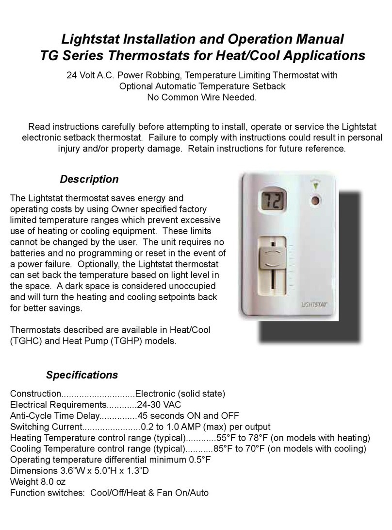
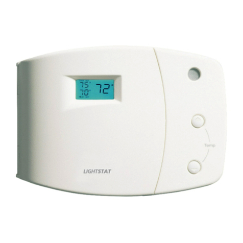
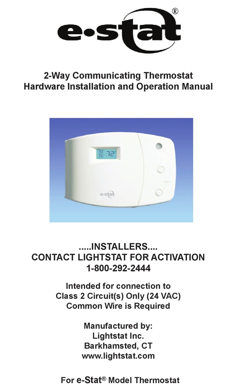
Lightstat e-stat Owner's manual

2-Way Communicating Thermostat
Hardware Installation and Operation Manual
Intended for connection to
Class 2 Circuit(s) Only (24 VAC)
Common Wire is Required
Manufactured by:
Lightstat Inc.
Barkhamsted, CT
www.lightstat.com
.....INSTALLERS....
CONTACT LIGHTSTAT FOR ACTIVATION
1-800-292-2444
For e-Stat™Model Thermostat

1
Supply
Ductwork Return
Ductwork
Roof Top Unit #1
Retail or restaurant
interior area
Your existing POS
computer and/or
network connection
e-Stat
Remote Room Sensor
Hub
Remote supply sensor is
located in supply ductwork
2-conductor
#18 low voltage
cable
2-conductor
#18 low voltage
cable
Existing
8-conductor
#18 low voltage
cable
Cat 6
cable
e-Stat Typical Wiring Configuration
1. Typically, the e-Stat™should be located within
a few feet of the network equipment such as the
network switch. It may be located farther. The
maximum Cat 6 cable run is 328 ft
(100 meters).
2. Mount the Remote Room Sensor on a wall or
column in the conditioned space, away from
windows, doors and supply air ducts. (Refer to
page 9 for more instructions.)
3. Mount the Supply Air Sensor in the supply air
duct as close to the HVAC unit as possible.
(Refer to page 10 for more instructions.)
Note: You must use the remote temperature
sensor supplied. The e-Stat™does NOT contain
an onboard temperature sensor.

2
Description:
The e-Stat™is a low voltage, solid state, automatic
changeover, heating/cooling thermostat with digital
display showing setpoints and room temperature.
The e-Stat™is a 2-Way Communicating, remotely
programmable thermostat.
Standard Features:
•Control of up to two stages of heating
and cooling.
• Proportional plus Integral (P+I) control for
accurate, even temperature control.
• Automatic changeover from heating to
cooling with deadband to prevent short
cycling of HVAC equipment.
• Remotely programmable, adjustable deadband.
(5°F is default)
• Remotely congurable Y1, Y2 interstage
differential. (1.5°F is default)
• Intelligent pre-conditioning of the controlled
space prior to the start of the workday.
• Automatic randomized delay to prevent power
surges at power up. (4 to 12 minutes)
• Backlit display for easy viewing in low light
conditions.
•Support for optional humidity sensing.
•Contact Closure terminal input to monitor switch
closure.
• Limited Lifetime Warranty.
General:
Voltage Rating (min, max).........................20 to 30 VAC
Current Draw (typ).............................285 mA @ 24VAC
A1-A2-A3 Relay Load (max)................1 Amp @ 24VAC
G, Y1, Y2, W1, W2, O/B Load (max)...1 Amp @24VAC
Network:
Cabling........................Cat6 (UTP) with RJ45 connector
Ethernet....................................10/100BT Auto-Sensing
Wiring Cable Distance (Max).................................328 ft

Inside View - Door (Left)
Inside View - Base (Right)
ON
1 2 3
This th ermostat receive s programming via
E thernet cable connection .
S ome limited temperature adjustment MAY
or MAY NOT be allowed via the UP and
DOWN buttons .
TEC H SUPPOR T 800-292-2444
P leasant Valley , C T
OFF ON
1
2
3
1
2
3
-Move to ON fo r ga s he at . F an contr olle d
by limit switch .
-L eave OFF for f an controlled by Light stat
in heat cycle (typical for electric heat ).
-Move to ON for no compressor time delays .
-L eave OFF for 3 minute compressor minimum r un
and minimum o time delays .
-Move to ON to increase the Heating (W1-W2) di erential
to 3 degrees for m ore e cient Heat Pump operation .
-L eave OFF for (W1-W 2) di erential of 1.5 degrees ,
typically used with Ele ctric or Gas heat .
W RA P 00003 R EV . ?
S WI TCH SE TTINGS
3

Connecting the Outputs
Caution: Risk of Electrical Shock - More than one
disconnect switch may be provided. Disconnect
all power to device before servicing.
Remove the old thermostat from the wall taking note of
the wire colors on the back of the mounting kit
provided. Thread the thermostat cable through the
hole in the back of the e-Stat™. Mount the e-Stat™
securely to the wall using the hardware provided.
The e-Stat™should be leveled for cosmetic reasons.
GENERAL HVAC WIRING DIAGRAM
e-Stat
G
R
Y1
W1
W2
C
O
Y2
B
CLASS 2 XFMR
SYSTEM
TRANSFORMER
HVAC
EQUIPMENT
TERMINAL
STRIP
20-30 VAC
ONLY
A2
A1
A3
G
R
Y1
W1
W2
C
O
Y2
B
MAY BE USED
FOR NIGHT
SHUTDOWN
OF DAMPERS
OR OTHER
EQUIPMENT.
RELAY LOAD:
1 A MP (MAX)
@ 24V AC
CONNECT
AS REQUIRED
BY HVAC
EQUIPMENT
A1-A2-A3
C ONTACT
TERMINALS
ON e-Stat
FAN
HEAT 1
20-30 VAC ONLY
(C OMMON)
(COMMON)
HEAT PUMPS
MAY REQUIRE
JUMPER
BETWEEN Y1
AND W1 TO
BRING ON
COMPRESSOR IN
BOTH HEATING
AND COOLING.
(SEE NOTES ON
PAGE 5) HEAT 2
COOL 1
COOL 2
4

R-Hot Wire; one side of the control (20 - 30 VAC)
transformer. If two hot wires are present (as with RC and RH)
determine if they come from separate transformers. The e-Stat™
must be installed on a single transformer
system.
G - Fan Wire.
W1 - First stage of heating.
Y1 -First stage of cooling.
When conventional rooftop equipment is selected, the interstage
differential is always 1.5°F. With heat pump switch #1 set to “ON”,
the interstage differential is 3.0°F for heating stages and 1.5°F for
cooling stages. (If using a humidity sensor, interstage differential
will increase during cooling to compensate for high humidity
conditions.)
C - Common or Neutral side of transformer. This must be
connected for the e-Stat™to operate.
W2 -Second stage of Heat or Auxiliary heat with heat pumps.
Y2 - Second stage of cooling.
O- This output will be active with a call for cooling.
Often used for heat pump reversing valve.
B- This output will be active with a call for heating.
(Connect O & B outputs as required by the HVAC equipment.)
Note: When connecting to a heat pump with Thermostat
Reversing Valve Control you will need to install a jumper
wire between W1 and Y1 at the e-Stat™. There should be no
connection between W1 on the e-Stat™ and the RTU terminal
strip. Aux heat is connected to W2.
Note: When connecting to a heat pump with Unit Reversing
Valve Control no jumper wire is required as the reversing valve is
positioned by the unit internal controls based on whether cooling
or heating is being called by Y1, Y2 or W1, W2.
A1, A2, A3 are dry contact relay terminals that may be used for
night shutdown of dampers or control of other equipment. This is a
separate relay with isolated contacts.
Relay load: 1 AMP (MAX) @ 24VAC.
Connecting the Outputs
5

A - Indicates day of the week.
B - Signal/Status L.E.D. Indicators.
C - Output designators.
D- Press once to see supply air temp and
“last program” information, 2nd press displays %
relative humidity (if a humidity sensor is in use).
E - Check button. Use to cancel time delays.
F- Temperature up/down buttons.
G - Fan On/Auto button.
H- System power button.
Front View - Front Door Open
Temp
ONFANAUTO
HEATSET
COOLSET
OVERRIDE
NEW PROGRAM
SYSTEM OFF
REL
HUMIDITY ERROR
REMOTE TEMP
MONTUEWEDTHUFRISATSUN
ON
ON
ON
ON
ON
ON
A
P
Cool 1
Cool 2
Fan
O
Heat 1
Heat 2
System
On/Off
Check Fan
On/Auto
Read
Sensor
Yellow -
Website
program
active
Red -
Utility Program
active
Press to cancel
Time delays
On – Constant Fan
Auto – Fan only with
Heat / Cool cycle
Press to read
Supply Air Sensor
& Humidity (Optional)
Web controlled thermostat.
Buttons may be disabled.
Tech Support 800-292-2444
Turns entire system off
F
B
H
D
E
G
C
A
6

7
A - Output indicators. Illuminated “ON” and arrow indicates
output is active. Flashing arrow and steady “ON” indicates
output is being held on by time delay. Flashing arrow alone
indicates output is being held off by time delay.
B - Cooling temperature setpoint.
C- Indicates day of the week.
D- Current remote room temperature, supply air temp, or
ambient humidity.
E - REL HUMIDITY will ash to indicate setpoint reduction is
active.
F- Antenna icon indicates that an ethernet carrier is sensed.
G- Remote temperature sensor indicator.
H- Indicates status of hosting server communications.
I - If arrow and “ON” are not illuminated, the output is off.
J - Heating temperature set point.
K - Fan On/Auto indicator.
L- Indicates system is off.
M- Ramp symbol will be illuminated if space is actively being
preheated or precooled.
N - Solid “OVERRIDE” indicates the program has been over-
ridden with the Up/Down buttons if allowed locally. Flashing
“OVERRIDE” indicates remote override.
O - “New Program” will illuminate when “Read Sensor”
button is pressed once (provided thermostat has been
programmed).
P- Indicates AM or PM Local time.
Display Designators
COOLSET
AUTO FAN ON
ON
ON
ON
ON
ON
ON MONTUEWEDTHUFRISATSUN
HEATSET
SYSTEM OFF
OVERRIDE
NEW PROGRAM
ERROR
REMOTE TEMP
REL
HUMIDITY
P
A
Cool 1
Cool 2
Fan
O
Heat 1
Heat 2
H
P
M
CB
JK
A
O
N
GF
E
L
D
I

The e-Stat™is used as a stand-alone thermostat to
control a single HVAC system. Do not attempt to con-
trol more than one HVAC unit with an e-Stat™
A Remote Temperature Sensor MUST BE installed for
the e-Stat™to function properly. A Supply Air Sensor is
optional.
All wiring should be a minimum of #18AWG. Shielding
is not required.
Wiring Layout
8
TYPICAL
ROOFTOP
UNIT
SUPPLY AIR DUCT
S UPPL Y AI R SENSOR
MOUNT ON DISCHARGE AIR DU CT W IT H
P RO BE I N DISCHARGE AIR ST REAM
REMOTE TEMPERATURE AND
HUMIDITY SENSOR
MOU NT IN SPACE TO B E CONT RO LLED
10 WIRE #18A WG
2 WIRE #18A WG
2 WIRE #18A WG
NETWORK
CABLE
DO NOT INSTALL ON THE BOTTOM OF THE DUCT
Cat-6/6e

Remote Sensor Installation
The e-Stat™must have a Remote Temperature Sensor
installed. A Supply Air Sensor is optional. These sensors
are supplied for each thermostat.
Note: See Appendix B for Remote Temperature and
Humidity Sensor.
Use #18 gauge 2-conductor twisted pair cable between the
e-Stat™and the remote sensors. Remote sensors are
unaffected by wire runs of up to 500 feet.
Remote sensors do not have polarity, either wire may be
connected to either terminal. Shielded cable is not required
for remote sensors.
Mount the remote temperature sensor in the area to be
heated and/or cooled. If the remote temperature sensor is
installed where the old thermostat was, use the supplied wall
plate for cosmetic reasons.
Connect the 2-conductor cable to the two terminals marked
Remote Temperature Sensor. These are located in the cen-
ter of the bottom terminal block as seen in the gure below.
Note that this sensor is not designed to be placed into a
moving air stream.
9
Wire Nuts
(supplied)
REMOTE ROOM SENSOR
WIRING DIAGRAM
RELAYS: G, W1, Y1, W2, Y2, O, B,
A1, A2, and A3 rated 24 V ac, 60 Hz,
Class 2, 1A, resistive / pilot duty.
A1-A2-A3 Relay: Normal
position indicated.
Contacts reverse during
Unoccupied (night) mode
or, via OFF signal from
website.
Dry contacts
are isolated.
C1 C2
Contact
Closure
Input
Supply
Air
Sensor
A
1
A
2
A
3
Remote
Room
Temperture
(& Humidity)
Sensor
Non-twisted Pair #18 AWG Wire
500 feet (maximum)
(not supplied)
Remote Room
Temperature
(& Humidity)
Sensor

Supply Air Sensor
Mount the Supply Air Sensor on the discharge air duct
with the probe in the discharge air stream making sure
the inner duct liner is penetrated, if present, so the
probe is in the air stream.The probe must be positioned
horizontally or downward. Do not place on the bot-
tom of the duct with the probe sticking up. Do not use
probe as a tool to puncture ductwork.
10
Connect the 2-conductor cable to the two terminals
marked Supply Air Sensor. These are located on the
bottom terminal block as seen in gure below.
Discharge
From RTU
To
Supply Air
Diffuser
Acceptable
Supply Air
Sensor
Locations
Unacceptable
Supply Air
Sensor
Location
Wire Nuts
(supplied)
(REMOTE) SUPPLY AIR SENSOR
WIRING DIAGRAM
RELAYS: G, W1, Y1, W2, Y2, O, B,
A1, A2, and A3 rated 24 V ac, 60 Hz,
Class 2, 1A, resistive / pilot duty.
A1-A2-A3 Relay: Normal
position indicated.
Contacts reverse during
Unoccupied (night) mode
or, via OFF signal from
website.
Dry contacts
are isolated.
C1 C2
Contact
Closure
Input
Supply
Air
Sensor
A
1
A
2
A
3
Remote
Room
Temperture
(& Humidity)
Sensor
Non-twisted Pair #18 AWG Wire
500 feet (maximum)
(not supplied)
Supply
Air
Sensor

11
When using the e-Stat™on a heat pump, move this
switch to the ON position. This will increase the
interstage differential between W1 and W2 from 1.5°F
to 3°F in the heating mode to allow the HVAC to
operate the compressor longer before turning on the
backup heat.
Moving this switch to ON also tells the e-Stat™to use
a different intelligent recovery warm up from the
unoccupied to the occupied mode, to minimize the use
of backup heat.
The recovery period is a maximum of 128 minutes.
The e-Stat™will automatically determine the amount of
time required to bring the space up to the
desired temperature setpoint.
During this recovery period, the e-Stat™will display the
“ramp” symbol in the digital display and the
temperature setpoints will ramp automatically.
Setting the Heat Pump Switch (#1)
ON
1 2 3
This th ermostat receive s programming via
E thernet cable conn ection .
S ome limited temperature adjustment MAY
or MAY NO T be allow ed via the UP and
DOWN buttons .
TEC H SUPPOR T 800-292-2444
P leasan t Valley , C T
OFF ON
1
2
3
1
2
3
-Move to O N fo r ga s he at . F an contr olle d
by limit switch .
-L eave OFF for fan controlled by Light stat
in heat cycle (typical for electric heat ).
-Move to ON for no compressor time del ays .
-L eave OFF for 3 minute compress or minimum r un
and minimum o time delays .
-Move to ON to increase the Heatin g (W 1-W2) di erential
to 3 degrees for m ore e cient Heat Pump operation .
-L eave O FF for (W 1-W2) di erential of 1.5 degrees ,
typically used with Ele ctric or Gas heat .
WRA P 00003 R EV . ?
S WI TCH SE TTINGS
ON
1 2 3
.
OFF ON
1
2
3
-L eave OFF for f an controlled by Light stat
in heat cycle (typical for electric heat ).
WRA P00003 R EV. ?
12 3
ON
OFF ON
1
2
3

12
When this switch is set to OFF, the minimum On and
Off time for any stage of Heating or Cooling will be 3
minutes.
When set to ON, no delays are used when heating or
cooling stages change state.
In either position, the Fan will continue to run for 45
seconds after the Heating or Cooling stops;
unless the Fan switch is set to ON in which case the
fan runs continuously.
During night setback the Fan will revert to the Auto
Mode.
Setting the Compressor Time Delay Switch (#2)
ON
1 2 3
This th ermostat receive s programming via
E thernet cable conn ection .
S ome limited temperature adjustment MAY
or MAY NO T be allow ed via the UP and
DOWN buttons .
TEC H SUPPOR T 800-292-2444
P leasan t Valley , C T
OFF ON
1
2
3
1
2
3
-Move to O N fo r ga s he at . F an contr olle d
by limit switch .
-L eave OFF for fan controlled by Light stat
in heat cycle (typical for electric heat ).
-Move to ON for no compressor time del ays .
-L eave OFF for 3 minute compress or minimum r un
and minimum o time delays .
-Move to ON to increase the Heatin g (W 1-W2) di erential
to 3 degrees for m ore e cient Heat Pump operation .
-L eave O FF for (W 1-W2) di erential of 1.5 degrees ,
typically used with Ele ctric or Gas heat .
WRA P 00003 R EV . ?
S WI TCH SE TTINGS
ON
1 2 3
.
OFF ON
1
2
3
-L eave OFF for f an controlled by Light stat
in heat cycle (typical for electric heat ).
WRA P00003 R EV. ?
123
ON
OFF ON
1
2
3

13
Setting the Heat Fan switch to Gas/Electric (#3)
This is often called the “Gas/Electric” switch.
Consult the HVAC equipment manufacturers’
instructions for details on how to set this switch.
When controlling fossil fueled equipment with a fan
limit control, you may want to set this switch to the ON
position.
Note: The e-Stat™will not bring on the fan in this
setting during the heat cycle.
Leave this switch set to OFF for all other
equipment, such as electric heat or heat pumps.
ON
1 2 3
This th ermostat receive s programming via
E thernet cable conn ection .
S ome limited temperature adjustment MAY
or MAY NO T be allow ed via the UP and
DOWN buttons .
TEC H SUPPOR T 800-292-2444
P leasan t Valley , C T
OFF ON
1
2
3
1
2
3
-Move to O N fo r ga s he at . F an contr olle d
by limit switch .
-L eave OFF for fan controlled by Light stat
in heat cycle (typical for electric heat ).
-Move to ON for no compressor time del ays .
-L eave OFF for 3 minute compress or minimum r un
and minimum o time delays .
-Move to ON to increase the Heatin g (W 1-W2) di erential
to 3 degrees for m ore e cient Heat Pump operation .
-L eave O FF for (W 1-W2) di erential of 1.5 degrees ,
typically used with Ele ctric or Gas heat .
WRA P 00003 R EV . ?
S WI TCH SE TTINGS
ON
1 2 3
.
OFF ON
1
2
3
-L eave OFF for f an controlled by Light stat
in heat cycle (typical for electric heat ).
WRA P00003 R EV. ?
1 2 3
ON
OFF ON
1
2
3

Use #18 gauge cable between the e-Stat™and the
damper or equipment to be controlled. Cables do not
need to be shielded.
The A1-A2-A3 terminals are an isolated set of dry
contacts rated 1 Amp at 24 VAC.
Connect the cable to the appropriate terminals marked
A1-A2-A3. Connect the other end to the damper or
equipment to be controlled as needed.
The default operation for A1-A2 is open during “oc-
cupied” period and closed during “unoccupied” period.
A2-A3 is closed during “Occupied” period and open
d ur i n g “ u no c c u pi ed ” p e ri o d .
Note: Alternatively, these contacts can be controlled
remotely via the Internet. See Appendix A.
14
A1-A2-A3 DRY CONTACT CLOSURE
WIRING DIAGRAM
RELAYS: G, W1, Y1, W2, Y2, O, B,
A1, A2, and A3 rated 24 V ac, 60 Hz,
Class 2, 1A, resistive / pilot duty.
A1-A2-A3 Relay: Normal
position indicated.
Contacts reverse during
Unoccupied (night) mode
or, via OFF signal from
website.
Dry contacts
are isolated.
C1 C2
Contact
Closure
Input
Supply
Air
Sensor
A
1
A
2
A
3
Remote
Room
Temperture
(& Humidity)
Sensor
Non-twisted Pair #18 AWG Wire
500 feet (maximum)
(not suppl ied)
May be used for
night shutdown of
dampers or other
equipment
A1-A2 = Normally
Open (N.O)
Contacts
A2-A3= Normally
Closed (N.C)
Contacts
1 Amp
(Max) @
24VAC

Powering up the e-Stat™
First you must turn on the breaker or switch that feeds
power to your HVAC equipment.
Next, press the blue System On/Off button to turn on
the e-Stat™.
The power-up sequence will give you information about
your e-Stat™.
IMPORTANT: The e-Stat™must be programmed
remotely. The thermostat will run the HVAC system on
default temperatures. After power up, this thermostat
must be activated in order for the customer to change
the programming. (see page 16 for activation
instructions).
You must connect the Cat 6 RJ45 jack in
order for the e-Stat™to communicate on the
network and be programmed.
15
ETHERNET CABLE (NETWORK)
WIRING DIAGRAM
Use supplied
Ethernet cable
If substituting Ethernet
cable length must not
exceed 328 feet
Connect to RJ -45 jack
positioned near eStat or to
a network hub, switch, or
router.
Networking equipment to
be supplied by others.
Temp
ONFANAUTO
HEATSET
COOLSET
OVERRIDE
NEW PROGRAM
SYSTEM OFF
REL
HUMIDITY ERROR
REMOTE TEMP
MONTUEWEDTHUFRISATSUN
ON
ON
ON
ON
ON
ON
A
P
Cool 1
Cool 2
Fan
O
Heat 1
Heat 2
System
On/Off
Check Fan
On/Auto
Read
Sensor
Yellow -
Website
program
active
Red -
Utility Program
active
Press to cancel
Time delays
On – Constant Fan
Auto – Fan only with
Heat / Cool cycle
Press to read
Supply Air Sensor
& Humidity (Optional)
Web controlled thermostat.
Buttons may be disabled.
Tech Support 800-292-2444
Turns entire system off
System
On/Off
Press to read
Supply Air Sensor
& Humidity (Optional)
Turns entire system off
F

Thermostat Activation
The e-Stat™thermostat must be activated after
installation. Activation only takes a few
minutes.
Information you will need before calling to activate your
e-Stat™:
1. Location Name, such as restaurant
or store name.
2. Store Number.
3. Thermostat TUID number (yellow label
afxed on the inside wrap of the
thermostat).
During the activation, Lightstat Support will be able to
bring on the heating and/or cooling for you to verify
proper equipment operation.
Depending on the model e-Stat™you have,
the temperature buttons may or may not work. If the
temperature up/down buttons function, do not use
these to test the HVAC operation prior to activation.
This will put the e-Stat™in override mode. If the word
“override” is in the display, you must turn the power off
and then back on in order to clear the override.
PLEASE CALL TO ACTIVATE THE
THERMOSTAT
1-800-292-2444
YOUR CUSTOMER CANNOT COMMUNICATE
WITH THE THERMOSTAT UNLESS IT HAS
BEEN ACTIVATED.
16

Green Button Functions
Check - Cancels all time delays (primarily used for
troubleshooting purposes).
Fan On/Auto - Some model thermostats may not have
a selectable fan function. If selectable, choose be-
tween “ON” (Constant Fan) or “AUTO” (Fan only with
heat or cool cycle) during OCCUPIED period.
Read Sensor - Press the “Read Sensor” button once
to see when the last program was received. This will
also display the supply air sensor temperature. Press
a second time to see the relative humidity (if an RTH
sensor is in use).
17
Check Fan
On/Auto
Read
Sensor
Press to cancel
Time delays On – Constant Fan
Auto – Fan only with
Heat / Cool cycle
Press to read
Supply Air Sensor
& Humidity (Optional)

Use the UP and DOWN temperature buttons to change
the heating and cooling setpoints. To conserve energy
and make sure that the heating and cooling units do
not ght each other, the heating and cooling setpoints
typically cannot be set closer than 5°F. Other “ONOFF
differentials” may be used. 3, 4 or 6°F can be selected
via the web interface.
The range of local temperature adjustment may be
restricted to owner specications.
On some models the temperature buttons may not
function.
If the temperature buttons function and they are used,
the word “OVERRIDE” will appear in the display. The
override period is determined by the communications
interface. When the override period expires, the
e-Stat™will revert back to its program.
Note: Not all e-Stat™sallow button adjustment of
temperature settings during the OCCUPIED period.
During the UNOCCUPIED program period pressing
either up or down buttons will adjust the setpoints to
the settings dened for the previously occupied state.
The previously occupied state setpoints will remain
in effect for 2 hours (time frame is adjustable) before
reverting back to the setpoints dened in the current
program. If previously occupied state data is
unavailable for the current day, default temperature
settings are used.
18
Setting Temperature

Output Status
Your e-Stat™will show the status of the HVAC system
outputs. It will indicate when the Fan, Heating or Cool-
ing should be running.
A solid arrow “◄” and the word “ON” in the display
indicates the output is on.
A ashing arrow “◄” and the word “ON” in the display
indicates the output has recently turned on and is being
held on by a time delay.
A ashing arrow “◄” by itself in the display indicates
the output has recently turned off and is being held off
by a time delay.
Note: Use the CHECK button to cancel equipment
time delays for faster checkout.
You can use the output indicators to help
troubleshoot your HVAC system. If the Cool 1 and
Cool 2 output indicators are displayed, you should feel
cool air coming from the HVAC system. This tells you
the HVAC system is working properly. Press “Read
Sensor” to see supply air temperature.
19
ON
ON
ON
ON
ON
ON
Cool 1
Cool 2
Fan
O
Heat 1
Heat 2
Check
Press to cancel
Time delays
Other manuals for e-stat
1
Table of contents
Other Lightstat Thermostat manuals
Popular Thermostat manuals by other brands

SiKom
SiKom SI-3 Installation and user guide

ClimateMaster
ClimateMaster iGate ATC32U02 user manual

Aprilaire
Aprilaire 8355 user manual

Carrier
Carrier TP-WEM01 Advanced installation and configuration instrucrions

Danfoss
Danfoss ECL Comfort 310, A361 installation guide

ensto
ensto ECO10BTW-J Installation and operating instructions

White Rodgers
White Rodgers 1F78 installation instructions

Lauda
Lauda RE 1050 G operating instructions

Lefroy Brooks
Lefroy Brooks X1-2010 Installation, operating and maintanance instructions

Alien green
Alien green Mostat Instructions for installation

HeatMat
HeatMat UFSTAT10 manual

Buderus
Buderus RC35 operating instructions