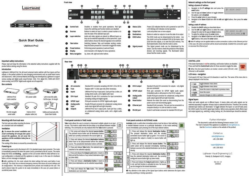
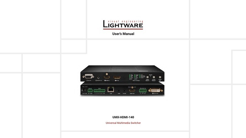
Lightware UMX-HDMI-140 User manual

UMX-HDMI-140
UMX-HDMI-140-Plus
User’s Manual
Universal Multimedia Switcher

UMX-HDMI-140 series– User's Manual 2
Important Safety Instructions
Class II apparatus construction.
The equipment should be operated only from the power source
indicated on the product.
To disconnect the equipment safely from power, remove the power
cord from the rear of the equipment, or from the power source. The
MAINS plug is used as the disconnect device, the disconnect device
shall remain readily operable.
There are no user-serviceable parts inside of the unit. Removal of the
cover will expose dangerous voltages. To avoid personal injury, do not
remove the cover. Do not operate the unit without the cover installed.
The appliance must be safely connected to multimedia systems.
Follow instructions described in this manual.
Ventilation
For the correct ventilation and to avoid overheating ensure enough
free space around the appliance. Do not cover the appliance, let the
ventilation holes free and never block or bypass the ventilators (if any).
WARNING
To prevent injury, the apparatus is recommended to securely attach to
The apparatus shall not be exposed to dripping or splashing and that
be placed on the apparatus.
Waste Electrical & Electronic Equipment
WEEE
This marking shown on the product or its literature,
indicates that it should not be disposed with other
household wastes at the end of its working life. To
prevent possible harm to the environment or human
health from uncontrolled waste disposal, please
separate this from other types of wastes and recycle it
responsibly to promote the sustainable reuse of material
resources. Household users should contact either the
retailer where they purchased this product, or their local government
environmentally safe recycling. Business users should contact their
supplier and check the terms and conditions of the purchase contract.
This product should not be mixed with other commercial wastes for
disposal.
Common Safety Symbols
Symbol Description
Direct current
Alternating current
Double insulation
Caution, possibility of electric shock
Caution

UMX-HDMI-140 series– User's Manual 3
Symbol Legend
The following symbols and markings are used in the document:
WARNING! Safety-related information which is highly
recommended to read and keep in every case!
ATTENTION! Useful information to perform a successful procedure;
it is recommended to read.
INFO: A notice which may contain additional information. Procedure
can be successful without reading it.
DEFINITION: The short description of a feature or a function.
TIPS AND TRICKS: Ideas which you may have not known yet but can
be useful.
Navigation Buttons
Go back to the previous page. If you clicked on a link previously,
you can go back to the source page by the button.
Navigate to the Table Contents.
Step back one page.
Step forward to the next page.
Document Information
This User’s Manual applies to the following versions of the mentioned
Item Version
Lightware Device Controller (LDC) software v1.27.0b2
Lightware Device Updater (LDU2) software v1.2.3b3
Controller rmware v1.2.0b12
Hardware 1.1
Document revision: 2.5
Release date: 09-04-2019
Editor: Judit Barsony
About Printing
Lightware Visual Engineering supports green technologies and
Eco-friend mentality. Thus, this document is made for digital usage
primarily. If you need to print out few pages for any reason, follow the
recommended printing settings:
▪Page size: A4
▪Output size: Fit to page or Match page size
▪Orientation: Landscape
TIPS AND TRICKS: Thanks to the size of the original page, a border
around the content (gray on the second picture below) makes
possible to organize the pages better. After punching the printed
pages, they can be placed easily into a ring folder.
123

UMX-HDMI-140 series– User's Manual 4
1. INTRODUCTION...................................................................................6
...................................................................................6
...............................................................................6
........................................................................... 6
.......................................................................................7
...................................................................8
2. INSTALLATION...................................................................................10
......................................................................10
......................................................................... 10
................................................... 10
.......................................................................11
3. PRODUCT OVERVIEW ......................................................................12
..................................................................................12
....................................................................................13
.............................................................13
........................................................................ 13
............................................................................... 13
............................................................................. 13
................................................................... 13
............................................................................... 14
................................................. 14
................................................. 14
...................................................... 14
........................................................................... 14
................................................................................. 15
............................... 15
.....................................................15
.............................................................................16
..........................................................................16
......................................................................... 16
................................................................ 17
..........................................................................17
......................................................................... 17
....................................................... 17
............................................ 18
......................................................................18
................................................................................ 18
...................................................................................... 20
.............................................................. 20
................................................................................ 21
............................ 21
.........................................................21
.................. 21
4. OPERATION .......................................................................................22
..............................................................22
........................................................................ 22
........................................................................ 22
..................................................................................... 22
................................................... 22
......................................................................22
........................................................... 22
............................................................... 22
.................................................. 22
.................................................................................... 23
........................................................................ 23
................................................. 23
..........................................................23
5. SOFTWARE CONTROL - LIGHTWARE DEVICE CONTROLLER ....24
..................................................................24
.........................................................................24
.....................................................25
........................................................................26
..........................................................27
....................................................................... 27
........................................................................ 28
...................................................................... 28
....................................................................... 29
........................................................................ 29
................................................................................... 30
................................................................................... 30
............................................................................... 31
.................................................................................... 31
...................................................................................32
.............................................................................. 32
................................................................. 33
............................................................................... 33
........................................... 34
............................................................................34
............................................................................................. 34
...................................................................... 35
................................................................................................ 36
........................................................................................... 36
................................................................................................. 37
...........................................................................39
.............................................................................. 39
.............................................................. 40
...................................................... 40
............................................................ 41
.............................................................. 41
............................................................... 41
............................................................................42
.............................................................................................. 42
............................................................................. 42
........................................................................................... 42
...................................................................................... 43
.................................................... 43
.......................................................................... 43
........................................ 44
.................................... 44
............................................................................................ 44
............................................................45
6. LW2 PROGRAMMER'S REFERENCE...............................................46
.........................................................46
.............................................................46
.......................................................................... 46
................................................................... 46
............................................... 47
.............................................................................. 47
........................................................................ 47
.................................................................................. 47
....................................................................... 47
.................................................. 47
.......................................................................... 47
.................................................................... 47
................................................. 47
......................................................................48
........................................................ 48
.................................................................................... 48
............................................................................... 48
..................................................................................... 48
................................................................................. 48
........................................... 49
...................................................................... 49
.................................................... 49
.................................................... 49
................................................ 50
......................................................... 50
.............................................................50
........................................................... 50
.......................................................................... 50
...................................................................... 50
............................................................... 51
.................................................................. 51
....................................................................51
........................................... 51
Table of Contents
UMX-HDMI-140 series– User's Manual 5
..............................................52
7. LW3 PROGRAMMERS’ REFERENCE...............................................53
.....................................................................................53
..........................................................................53
........... 53
.................................................................................. 53
............................................................................. 54
.............................................................................. 54
............................................................................... 54
.......................................................................................... 54
......................................................................................... 55
.................................................................................... 55
..................... 55
............................................. 55
......................................................................56
................................................................ 56
....................................................................... 56
................................................................ 56
.......................................................... 56
....................................................................... 56
............................................ 56
........................................................ 57
...........57
.................................................................................57
.......................................................................... 57
...................................................................58
.................................................. 58
............................................ 59
.............................................. 59
.................................................................... 59
............................................. 59
........................................................ 59
.......................................................... 60
....................................................... 60
.......................................................................... 60
................................................................... 60
........................................................................ 60
..................................................................... 60
.................................................................................. 61
............................................................................. 61
.................................................................................. 61
............................................................................... 61
............................................................ 61
Table of Contents ................................................................. 61
......................................................... 62
............................................. 62
............................................... 62
...................................................................63
.................................................... 63
............................................ 63
............................................................................ 64
........................................................................ 64
......................................................................... 64
..................................................................... 64
................................................ 64
.............................................................65
.................................................................... 65
................................................................. 65
...................................................................... 65
..................................................... 65
.................................................................. 65
.................................................. 65
.......................................................... 65
.......................................... 66
.......................................................66
.............................................................................. 66
.......................................................................... 66
................................................................................ 66
.............................................................................. 66
................................................................................... 67
................................................................. 67
............................................................. 67
.....................................................................67
.................................................................... 67
...................................................................... 68
.............................................................................. 68
.. 68
...................... 68
................................ 68
................................................................... 69
....................................................69
................................................. 69
.................................... 69
.....................70
................................................... 70
............................................ 70
.................................... 71
........................................................... 71
............................................................. 72
. 73
.... 73
.........................................................73
.................................................... 73
.............................................. 73
.................................................... 73
.....................................................................74
........................................................... 74
......................................... 74
........................ 74
............................................. 74
........................................... 74
.................................................... 75
.......................................... 75
..................................................... 75
.................................................................76
8. FIRMWARE UPGRADE......................................................................79
............................................................79
...................................79
...............................................................................79
........................................................80
.........................................81
9. TROUBLESHOOTING........................................................................82
10. TECHNOLOGIES..............................................................................84
.....................................................................84
............................................................... 84
...................................................... 84
...................................................................85
........................................... 85
................................................. 85
......................................................86
11. APPENDIX ........................................................................................87
............................................................................87
............................................................88
.................................................89
..............................................................89
.........................................................90
...........................91
........................................................91
.....................................................................92
..............................................................93

1. Introduction UMX-HDMI-140 series– User's Manual 6
1
Introduction
Thank you for choosing Lightware’s UMX-HDMI-140 series switcher family. In
important features in the below listed sections:
Box Contents
Model Comparison
UMX-HDMI-140 UMX-HDMI-140-Plus
Video Ports
VGA input
HDMI input
DisplayPort input
DVI-I input
Analog Stereo Audio Ports
3.5 mm Jack input
5-pole Phoenix input
Control Ports
RS-232 (3-pole Phoenix)
IR emitter (3.5 mm Jack)
IR detector (3.5 mm
Jack)
GPIO (8-pole Phoenix)
Ethernet (RJ45)
Nr. of Events in Event
Manager 40 100
IR message sending -
CEC message sending -
RS-232 message
recognizer -
UMX-HDMI-140
switcher
12V DC adaptor with
interchangeable plugs
Phoenix®Combicon
3-pole connector
Phoenix®Combicon
5-pole connector
Phoenix®Combicon
8-pole connector
Safety & warranty info,
Safety and
Warranty
Info
Quick
Start
Guide
Description
UMX-HDMI-140 switches universal 4K video and audio to a HDMI
output port. This device was designed for digital and analog video
and audio signals: VGA, DVI, HDMI 1.4 and DP 1.1 with analog stereo
audio from local inputs or embedded 7.1 HBR audio. The unit can also
handle HDCP encryption. Analog signals (both audio and video) are
converted into digital format. Using the factory, custom or transparent
connector. Advanced EDID Management forces the required resolution
system requirements.
The Advanced Control feature pack includes functions which help to
system automation challenges. In small to mid-size systems, these
automation features can help to dismiss an additional control
processor box, thus lowering integration time and costs.
The device can be mounted on a rack shelf or used standalone.
UMX-HDMI-140 is compatible with HDMI extenders and matrix
switchers.
Model Denomination
About the Serial Number
Lightware devices contain a label indicating the unique serial number
of the product. The structure is the following:
UMX-HDMI-140-Plus
HDMI output interface
Universal input interfaces - analog and
digital signals are also accepted
1x output and 4x inputs
with Advanced
Control Features
7A000941
Year of the manufacturing (3-9, A-Y):
7=2017, 8=2018, 9=2019, A=2020, etc...
6-digit running sequence number
Month of the manufacturing (1-9, A-C):
1=January, 2=February, ..., C=December
Î
Î
Î
Î

1. Introduction UMX-HDMI-140 series– User's Manual 7
High bandwidth allows extension of resolutions up to 4K
and even 3D sources and displays are supported.
Analog audio and video signals are converted to digital
before being sent to the output.
Pixel Accurate Reclocking
Each output has a clean, jitter free signal, eliminating
signal instability and distortion caused by long cables or
HDCP-compliant
on the digital video inputs can be disabled when non-
protected content is extended.
Built-in Event Manager
The Event Manager tool takes care of all the necessary
Hence, in a less complex environment, there is no need
to invest in additional control solutions, which makes the
receiver the best choice for numerous applications.
The Autoselect feature can sense the port status on the
video input ports and select automatically one of them.
Priority number can be set for each input port and the
feature allows to set various modes for the automatic
input selection (First detect, Last detect, Priority mode).
RS-232 Bi-directional RS-232 Pass-through
AV systems can also contain serial port controllers and
controlled devices. Serial port pass-through supports
any unit that works with standard RS-232.
GPIO Control Port
7 GPIO pins operating at TTL digital signal levels and can
CEC Consumer Electronic Control
Supports transmitting standard CEC commands in order
to remote control the source or sink device.
Infra Message Sending
Infrared (IR) is a wireless technology used for device
communication over short ranges. Third party control
systems may send IR control commands to endpoints
turning them on and off or switching their inputs.
RS-232
11 0100 1
x
RS-232 Recognizer
Support recognizing incoming RS-232 messages to
integrate with 3rd party devices like VC codec.

1. Introduction UMX-HDMI-140 series– User's Manual 8
Typical Applications
The typical application of the UMX-HDMI-140 switcher:
▪Small meeting rooms
▪Huddle rooms
▪Home cinema
The following drawings introduce three simple examples how you can apply the device in different
environments.
Huddle Room with Speakers
UMX-HDMI-140
HDMI-4K
De-embedder
Mounted
under desk
ETHERNET
MacBook
HDMI
Laptop
HDMI
Laptop
VGA
Laptop
HD Display
Active
speakers
Power over
HDMI
(up to 20 m)
Display control over RS-232
1.35/3.5mm
Volume control
PIN:2.1mm GPIO
RS-232
TXRX
AUDIO2IN
DVI-IIN
IRIN IR OUT
SIGNAL HDCP
12V1A DC
Thunderbolt/DisplayPort
HDMI
Analog audio
LAN
VGA
RS-232
The Concept
The huddle room has an HD Display and dedicated audio sink devices. The UMX-HDMI-140 switcher is
assembled under the desk in an Under-desk Double Mounting Kit. The cables for the input sources are guided
below the desk's surface to a cable box. The visitors of the huddle room can use their laptops built with VGA,
HDMI, DVI, DisplayPort, or Thunderbolt connectors as well. The device also accepts analog audio signals
from two different sources. You can see all accepted interfaces of the device in the Electrical Connections
section.
embedder de-embeds the audio signal and transmits it to the Active speakers. The De-embedder does not
need local powering because it can be supplied via the HDMI cable by the source and the cable extensions
can be up to 20 meters thanks to the built-in Pixel Accurate Reclocking technology of the Lightware devices.
The Switcher and also the De-embedder can be controlled easily via LAN network using our controller
software (LDC); see the details in the Software Control - Lightware Device Controller chapter.
The HD Display can be also controlled via the UMX-HDMI-140 by RS-232 interface.

1. Introduction UMX-HDMI-140 series– User's Manual 9
Video Conference Room
The Concept
The VC (Video Conference) room has an HD Display, Active speakers, and Video conference codec. The
UMX-HDMI-140 switcher is assembled under the desk in an Under-desk Double Mounting Kit. The cables for
the input sources are guided below the desk's surface to a cable box. The visitors of the huddle room can
use their laptops built with VGA, HDMI, DVI, DisplayPort, or Thunderbolt connectors as well. The device also
accepts analog audio signals from two different sources. You can see all accepted interfaces of the device
in the Electrical Connections section.
The number of the inputs of the Video conference codec is extended by the Switcher as its output is
connected to the input of the VC. The Switcher can be controlled easily via LAN network using our controller
software (LDC); see the details in the Software Control - Lightware Device Controller chapter.
The HDMI cable between the Switcher and the codec can be up to 20 meters thanks to the built-in Pixel
Accurate Reclocking technology of the device.
Videoconference
Codec
UMX-HDMI-140
Mounted
under desk
HDMI
(10-20 m)
ETHERNET
MacBook
HDMI
Laptop
HDMI
Laptop
VGA
Laptop
HD Display
Active
speakers
PIN:2.1mm GPIO
RS-232
TXRX
AUDIO2IN
DVI-IIN
IRIN IR OUT
SIGNAL HDCP
12V1A DC
Thunderbolt/DisplayPort
HDMI
Analog audio
LAN
VGA
Collaboration Room with Ceiling Mounted Projector
The Concept
The Collaboration Room is built with a ceiling mounted projector and a projection screen. The output of
UMX-HDMI-140 is connected to the projector by HDMI cable which can be extended up to 40 meters using
a Lightware HDMI-Extender device. The HDMI-Extender does not need local powering because it can be
supplied via the HDMI cable.
The Switcher can be controlled easily via LAN network using our controller software (LDC); see the details in
the Software Control - Lightware Device Controller chapter.
As an additional feature the Switcher can control the projection screen indirectly. Connect a relay box to
information about it in the GPIO Interface section.
Power over
HDMI
(up to 40 m)
UMX-HDMI-140
Mounted
under desk
Thunderbolt/DisplayPort
HDMI
Analog audio
LAN
VGA
ETHERNET
MacBook
HDMI
Laptop
HDMI
Laptop
VGA
Laptop
HDMI-Extender
OUTPUT
POWER
ACTIVE
HD Projector
PIN:2.1mm GPIO
RS-232
TXRX
AUDIO2IN
DVI-IIN
IRIN IR OUT
SIGNAL HDCP
12V1A DC

2. Installation UMX-HDMI-140 series– User's Manual 10
2
Installation
The chapter is about the installation of the device and connecting to other
appliances, presenting also the mounting options and further assembly steps:
Mounting Options
To mount the switcher Lightware supplies optional accessories for
different usage. There are two kinds of mounting kits with similar
on the bottom side; see the bottom view in the Mechanical Drawings
section. Fasten the device by the screws enclosed to the accessory:
Under-desk double mounting kit
1U high rack shelf
The Under-desk double mounting kit makes easy to mount a single
mounting holes for fastening two half-rack or four quarter-rack sized
units. Pocket-sized devices can also be fastened on the shelf. To order
INFO: The switcher is half-rack sized.
1U High Rack Shelf
Allows rack mounting for half-rack, quarter-rack and pocket sized
units.
1U high rack shelf provides mounting holes for fastening two half-
rack or four quarter-rack sized units. Pocket sized devices can also be
fastened on the self.
VIDEO AUDIO
DVI-AVideo
Autoselect
LIVE
Audio2
DVI-D
DP
DVI-D
DP
SHOW
ME
AUDIO
SELECTINPUT STATUS
VIDEO
SELECT
HDMI HDMI
VGA Audio1 RESET
AUDIO1 IN HDMI IN DPINVGA IN
VIDEO AUDIO
DVI-AVideo
Autoselect
LIVE
Audio2
DVI-D
DP
DVI-D
DP
SHOW
ME
AUDIO
SELECTINPUT STATUS
VIDEO
SELECT
HDMI HDMI
VGA Audio1 RESET
AUDIO1 IN HDMI IN DPINVGA IN
surface (e.g. furniture).
INFO: The chipboard screws are not supplied with the mounting kit.
VIDEO AUDIO
DVI-AVideo
Autoselect
LIVE
Audio2
DVI-D
DP
DVI-D
DP
SHOW
ME
AUDIO
SELECTINPUT STATUS
VIDEO
SELECT
HDMI HDMI
VGA Audio1 RESET
AUDIO1 IN HDMI IN DPINVGAIN
Î
Î

2. Installation UMX-HDMI-140 series– User's Manual 11
Connecting Steps
VGA laptop HDMI laptop
Power GPIO IR
HDTV
EthernetPower adaptor Infrared
UMX-HDMI-140
PC MacBook
HDMI DVI
VGA DP
Audio HDMI
Relay box
LAN
RS-232
VIDEO AUDIO
DVI-A Video
Autoselect
LIVE
Audio2
DVI-D
DP
DVI-D
DP
SHOW
ME
AUDIO
SELECTINPUT STATUS
VIDEO
SELECT
HDMI HDMI
VGA Audio1 RESET
AUDIO1 IN HDMI IN DP INVGA IN
HDMI
DVI
DP
VGA
cables.
Audio
Optionally connect an audio device (e.g. the VGA laptop) to the audio input port.
HDMI
Connect the sink (e.g. HDTV) to the HDMI output port by an HDMI cable.
RS-232
port.
IR
Optionally for Infrared control:
- Connect the IR emitter to the IR OUT port of the device.
- Connect the IR detector to the IR IN port of the device.
LAN
Optionally connect the switcher to a LAN network in order to control the device.
GPIO
Power

3. Product Overview UMX-HDMI-140 series– User's Manual 12
1VGA input D-SUB connector for analog video
signal.
2Audio1 input 3.5 mm Jack connector for asymmetric
analog audio input signal.
3HDMI input HDMI connector for DVI video or HDMI
video and audio.
4DisplayPort input DisplayPort connector for DisplayPort
5Input Status LEDs LEDs give feedback about the current
status of the unit and input signals.
See the details in the next section.
6Video Select
button
Button for switching between video
sources.
7Reset button Pushing the button reboots the unit.
8Audio Select
button
Button for switching between audio
sources.
9Show Me button Special functions can be reached
using this button (bootload mode,
DHCP settings, restore factory default
settings, condition launching in Event
Manager).
INFO: Both UMX-HDMI-140 and UMX-HDMI-140-Plus have the same
look and controls on the front panel.
17
2 3 4
5
6 8 9
3
Product Overview
output ports and connectors:
Status LEDs
Input Status LEDs
Input is not selected.
Input is selected, and signal is not detected.
ON: Input is selected and signal is present.
ATTENTION!
even though the device is fully functional.
LIVE LED
Device is not powered.
Device is powered and operational.
ON: Device is powered but not operational.
AUTOSELECT LED
Autoselect function is disabled.
Autoselect function is enabled, searching for signal
(the video input LEDs are also blinking).
ON: Autoselect function is enabled, the active video signal is
found (the selected video input's LED is also ON).
VGA
HDMI
DP
DVI-D
Audio1
HDMI
DP
DVI-D
LIVE
Autoselect
DVI-A Video
Audio2
VIDEO AUDIO
VGA
HDMI
DP
DVI-D
Audio1
HDMI
DP
DVI-D
LIVE
Autoselect
DVI-A Video
Audio2
VIDEO AUDIO
VGA
HDMI
DP
DVI-D
Audio1
HDMI
DP
DVI-D
LIVE
Autoselect
DVI-A Video
Audio2
VIDEO AUDIO
Î
Î
Î
Î
Î
Î
Î
Î
Î

3. Product Overview UMX-HDMI-140 series– User's Manual 13
Rear View
112V DC input
connector
12V DC input for local powering. For more
details see the next section.
2RS-232
connector
3-pole Phoenix connector for controlling
the device with LDC or third-party control
systems, or third-party device control. Pin
assignment can be found in the RS-232
Connector section.
3GPIO
assignment can be found in the GPIO -
section.
4Ethernet
the device using Lightware Device
Controller (LDC), or upgrading it using
Lightware Device Updater (LDU). Any
third-party control system can use this
port to control the device.
5IR IN and OUT 3-pole TRS connector, also known as
receiver (IR IN) and transmitter (IR OUT)
connection. Pin assignments can be
found in the IR Connector section.
6HDMI OUT HDMI output port for DVI or HDMI signal.
Connect an HDMI cable between the
switcher and the display device. Applied
cable shall not be more, than 30 m (when
the signal is 1080p) and and maximum
cable length varies between 5 meters
and 20 meters for 4K signals depending
on cable quality and the display's
equalization.
16
2 3 4 5 7 8
7Audio2 input 5-pole Phoenix connector for balanced
analog audio input. Pin assignment can
be found in the Analog Stereo Audio
(AUDIO2 IN) section.
8DVI-I input
signals.
INFO: Both UMX-HDMI-140 and UMX-HDMI-140-Plus have the same
look and controls on the rear panel.
HDMI OUTPUT LEDs
SIGNAL LED
Signal is not present on output.
ON: Signal is present on output.
HDCP LED
Output signal is not HDCP-
encrypted.
Non-HDCP capable device is
connected, encrypted signal is
replaced with red screen.
ON: Output signal is HDCP-encrypted.
HDMI OUT
HDCP
SIGNAL
HDMI OUT
HDCP
SIGNAL
Electrical Connections
12V DC Connection
Locking DC connector
Do not forget to turn the plug clockwise direction before disconnecting
the power adaptor.
WARNING! Always use the supplied 12V power adaptor. Warranty
void if damage occurs due to use of a different power source.
VGA Connector
The switcher provides a standard 15-pole
D-SUB female connector for connecting VGA
devices. Always use high-quality VGA cable for
connecting sources and displays; using a VGA cable where all the pins
are wired (including the DDC channel's wires) is highly recommended.
HDMI Connector
The extender provides standard 19 pole HDMI connector
for output. Always use high quality HDMI cable for
connecting sources and displays.
DisplayPort Connector
UMX-HDMI-140 switcher provides standard 20-pole
DisplayPort connector for input. Always use high quality
DP cable for connecting DisplayPort devices.
12V
1A
DC
12V
1A
DC
PIN: 2.1mm
PIN: 2.1mm

3. Product Overview UMX-HDMI-140 series– User's Manual 14
DVI-I Connector
UMX-HDMI-140 switcher provides a standard 29-pole DVI-I connector
for input where digital and analog pins are connected internally. Hence
users can use the connector receiving DVI-A (analog video) and DVI-D
signals (digital video and digital audio) as well.
ATTENTION! Only one (DVI-A or DVI-D) mode is available at a same
time. You can use the Video Select button to choose the input
source.
Always use high quality DVI cable for connecting DVI devices.
The following drawing and table show the pinout of DVI-I connector
and the position of analog and digital signal pins.
Pin Signal Pin Signal
1TMDS Data2- 16 Hot Plug Detect
2TMDS Data2+ 17 TMDS Data0-
3TMDS Data2 Shield 18 TMDS Data0+
4not connected 19 TMDS Data0 Shield
5not connected 20 not connected
6DDC Clock 21 not connected
7DDC Data 22 TMDS Clock Shield
8Analog Vertical Sync 23 TMDS Clock+
9TMDS Data1- 24 TMDS Clock-
10 TMDS Data1+ C1 Analog Red
11 TMDS Data1 Shield C2 Analog Green
12 not connected C3 Analog Blue
13 not connected C4 Analog Horizontal Sync
14 +5V Power C5 GND
15 GND (for +5V)
1 2 3 4 5 6 7 8
9 10 11 12 13 14 15 16
C1 C2
C4C3
C5
17 18 19 20 21 22 23 24
The connector is used for receiving unbalanced analog audio
phone jack, phone plug and mini-jack plug.
Pin nr. Signal
1 Left
2 Right
3 Ground
Jack audio plug pin assignments
Audio
Interface section.
5-pole Phoenix connector is used for balanced analog
audio input. Unbalanced audio signals can be connected
as well. See more details about the balanced and unbalanced input
port wiring in the section.
Pin nr. Signal
1 Left+
2 Left-
3 Ground
4 Right-
5 Right+
Analog audio connector and plug pin assignments
Compatible Plug Type
Phoenix®
Audio Interface section.
1 2 3
1 2 3 4 5
The extender provides standard RJ45 connectors for
TPS IN and LAN ports. Always use high quality Ethernet
cable for connecting transmitters and receivers.
Wiring of TPS and LAN Cables
Lightware recommends the termination of LAN cables on the basis of
RS-232 Connector
The receiver contains a 3-pole Phoenix connector which is
used for RS-232 serial connection.
Pin nr. Signal
1 Ground
2 TX data
3 RX data
RS-232 connector pin assignments
Compatible Plug Type
Phoenix®
Serial
Interface section.
18
1
8
Top
8
1
Bottom Side
Pin Color and name Color and name
1
2green solid orange solid
3
4blue solid blue solid
5
6orange solid green solid
7
8brown solid brown solid
1 2 3

3. Product Overview UMX-HDMI-140 series– User's Manual 15
IR Connector
IR detector and IR emitter can be connected to the receiver with TRS (Tip, Ring, and Sleeve) connectors.
plug. The pin assignments are the following for the detector and the emitter:
1 2 3
1 2-3
1 Tip Signal (active low) 1 Tip +5V
2 Ring GND 2 Ring Signal (active low)
3 Sleeve +5V 3 Sleeve
INFO: Ring pole of the emitter is optional. If your IR emitter has three pole-TRS plug, then the Ring and the
Sleeve are the same signal (Output - ).
IR Interface section.
UMX-HDMI-140 switcher contains a 8-pole Phoenix connector with seven GPIO pins,
which operates at TTL digital signal levels and can be set to high or low level (Push-Pull).
The direction of the pins can be input or output (adjustable). Voltage ranges for GPIO inputs are the following:
Input voltage [V] Output voltage [V] Max. current [mA]
Logical low level 0 - 0.8 0 - 0.5 30
Logical high level 2 - 5 4.5 - 5 18
INFO: The maximum total current for the seven GPIO pins is 180 mA.
Pin nr. Level and
direction
1
2
3
4
5
6
7
Ground
GPIO connector and plug pin assignments
Compatible plug type
Phoenix®
GPIO Interface section.
1 2 3 4 5 6 7
Universal Switcher Concept
functions. The device receives analog (VGA, DVI-A) and digital (DP, HDMI, DVI-D) video signals and transmits
device can be controlled via Ethernet, RS-232 or Infrared and is able to control third-party devices via the
RS-232, Ethernet, Infrared interfaces.
HDMI
INPUT OUTPUT
VGA
HDMI
DP
DVI-D
DVI-A
Analog audio
+ Ethernet
+ RS-232
+ Infrared
+ GPIO
VIDEO AUDIO
DVI-A Video
Autoselect
LIVE
Audio2
DVI-D
DP
DVI-D
DP
SHOW
ME
AUDIO
SELECTINPUT STATUS
VIDEO
SELECT
HDMI HDMI
VGA Audio1 RESET
AUDIO1 IN HDMI IN DP INVGA IN

3. Product Overview UMX-HDMI-140 series– User's Manual 16
Port Diagram
Port diagram
The device has four video input ports to receive analog video (VGA, DVI-A) and digital video (HDMI, DP,
signal is routed toward the HDMI output port. The device also has two analog audio input ports (3.5mm
Jack, 5-pole Phoenix). The analog signals are converted to digital ones. The user can choose which audio
signal is transmitted on the HDMI output port: one from the analog audio sources or the original embedded
INFO: The DVI-D input accepts HDMI signal with embedded audio as well.
Besides, the switcher has four different interfaces to control the unit itself or third-party devices: infrared
(input and output), RS-232, Ethernet, and GPIO.
HDMI in
VGA in
DP in
DVI in
Analog
audio in 1
Analog
audio in 2
Analog audio
Analog video
Digital video + Digital audio
Analog video
Analog audio Digital audio
A/D converter
Digital audio
5:1 digital
A/V switch
Digital video + Digital audio
Digital
audio
Digital video HDMI out
A/D converter
Embedder
A/D converter
A/D converter
3:1 digital
audio switch
De-embedder
Digital
audio
Audio Interface
Audio Input Modes
The device can receive embedded digital audio signal on the HDMI, DisplayPort, and DVI-D input ports and
analog audio signal on the Jack and the Phoenix input ports.
Audio Embedding
The switcher has a built-in audio embedder function which means the audio signal being received on the
analog audio input port can be embedded to the HDMI output.
The video and audio inputs can be combined with limitations. Below table contains the allowed connections:
Audio sources
HDMI DP DVI-D Analog audio 1 Analog audio 2
Video sources
HDMI - -
DP - -
DVI-D - -
VGA ---
DVI-A - - -
Allowed audio connections
ATTENTION! Audio embedding is available where the pixel clocking of the video signal is up to 225 MHz.
If the output video is 4K, the audio embedding function is not available.

3. Product Overview UMX-HDMI-140 series– User's Manual 17
Audio Options - Example
The Concept
Three audio sources are connected to the switcher: a Blu-ray player on the HDMI input (embedded HDMI
audio); a Laptop on the analog audio input 1; and a Media player on the analog audio input 2. There are two
video sources as well: the Blu-ray player on the HDMI input (digital video with the embedded audio) and the
Laptop on the VGA input (analog video).
▪If the video input source of the HDTV is the Blu-ray player, you can select from the following audio
sources:
–the original embedded HDMI audio from the Blu-ray player;
–the analog audio input 1 from the Laptop;
–the analog audio input 2 from the Media player.
▪If the video input source of the HDTV is the Laptop, you can select from the following audio sources:
–the analog audio input 1 from the Laptop;
–the analog audio input 2 from the Media player.
HDMI IN HDMI OUT
UMX-HDMI-140 switcher HDTV
Media player
ANALOG AUDIO IN 2
Laptop
VGA IN
Blu-ray player
ANALOG AUDIO IN 1
VIDEO AUDIO
DVI-AVideo
Autoselect
LIVE
Audio2
DVI-D
DP
DVI-D
DP
SHOW
ME
AUDIO
SELECTINPUT STATUS
VIDEO
SELECT
HDMI HDMI
VGA Audio1 RESET
AUDIO1 IN HDMI IN DP INVGA IN
Video Interface
Video Input Modes
The device can receive digital video signal on the HDMI, DisplayPort, and DVI-D input ports and analog video
signal on the VGA and the DVI-A input ports.
INFO: Both the DVI-A and DVI-D signals can be received on the same DVI-I input port.
Input Source Selection Modes
Video input source can be selected the following ways:
▪pressing Video Select button on the device;
▪using Lightware Device Controller (LDC);
▪
▪using the Autoselect function.
There are three types of Autoselect as follows.
▪First detect mode: selected input port is kept
connected to the output as long as it has
an active signal.
▪Priority detect mode: always the highest
priority active input is selected to transmit.
▪Last detect mode: always the last attached
input is selected to transmit.
Flowchart of Autoselect modes
New event?
„First detect” „Last detect”
No Audio/Video
transmission
Remains
selected
Last connected
input is selected
Y
„Off”
N
N
Current
Autoselect mode
„No signal”
Port with
priority 0 has a
valid signal?
Selected
port still has a
valid signal?
„Priority detect”
Port with
priority 1 has a
valid signal?
N
N
Port with
priority 30 has a
valid signal?
N
Display
Test pattern
Test
pattern generator
setting
Y
Y
Port with
priority 2 has a
valid signal?
N
Port with priority
0 is selected
Port with priority
1 is selected
Port with priority
2 is selected
Port with priority
30 is selected
Y
Y
Y

3. Product Overview UMX-HDMI-140 series– User's Manual 18
Automatic Input Selection - Example
The Concept
If there is no other source connected to the switcher, but the Laptop, VGA input will be automatically switched
to the HDMI output. If the Laptop and the PC are also connected to the switcher, DVI-D input will be switched
to the HDMI output. If the Blu-ray player is connected on the HDMI input, and later the MacBook is connected
on the DP input of the switcher, it will be switched to the HDMI output – independently of the presence of
other video signals.
Settings
▪HDMI output: Set the Autoselect to Enabled. Set Autoselect mode to Priority detect. The priorities are the
following (the lowest number means the highest priority):
Source device Input interface Input port Priority
MacBook DP IN I3 0
Blu-ray player HDMI IN I2 1
PC DVI-D IN I4 2
Laptop VGA IN I1 3
Priorities can be set in Lightware Device Controller software, see related settings in the Video Output section.
Laptop Projector
Blu-ray playerPC
HDMI OUT
DP IN
VGA IN
HDMI IN
DVI-D IN
UMX-HDMI-140 switcherMacBook
VIDEO AUDIO
DVI-AVideo
Autoselect
LIVE
Audio2
DVI-D
DP
DVI-D
DP
SHOW
ME
AUDIO
SELECTINPUT STATUS
VIDEO
SELECT
HDMI HDMI
VGA Audio1 RESET
AUDIO1 IN HDMI IN DP INVGA IN
Serial Interface
Technical Background
Serial data communication can be established via the local RS-232 port (Phoenix connector). Three different
RS-232 modes can be set for the serial port: Control mode, Command Injection mode, or Event Manager
Block diagram of UMX-HDMI-140 serial interface
1The serial port is in Control mode.
2The serial port is in Command Injection mode.
3The serial port is in Event Manager mode.
INFO: All settings are available in the LDC software, see details in the RS-232 section.
Only one mode can be used at a time: Control mode, Command Injection mode, or Event Manager mode.
Control Mode
The incoming data from the given port is processed and interpreted by the CPU. The mode allows to control
Command Injection Mode
LAN
port
RS-232
local
CPU
Mode
switch
3
2
1
Event Manager
use
Device control
Local RS-232 /
TCP converter

3. Product Overview UMX-HDMI-140 series– User's Manual 19
Event Manager Mode
Third-party devices can be controlled from Event Manager in this mode. ASCII characters and binary data in
hexadecimal format can be used in this case.
The following ways are available for controlling the devices:
▪The System controller sends messages over the LAN port of the Switcher to the given port number. The
Switcher converts the incoming TCP messages to RS-232 commands and transmits over the local
RS-232 port to the HDTV. The local RS-232 port has to be set to Command Injection mode. In this case
the direction of the communication is bi-directional between the Switcher and the System controller,
so the answer of the HDTV is received by the System controller.
▪The Switcher sends a "power on" message to the HDTV via the RS-232 port if signal is received on the
DVI-D input. In this case the RS-232 port has to be set to Event Manager mode and an event has to be
created where the condition is "signal is received on I4" and the action is "send a message on RS-232
port". Find a detailed example for the serial message sending in the Event Creating - Example section.
System controller
LAN
DVI-D IN
RS-232
PC UMX-HDMI-140 switcher HDTV
HDMI OUT
VIDEO AUDIO
DVI-AVideo
Autoselect
LIVE
Audio2
DVI-D
DP
DVI-D
DP
SHOW
ME
AUDIO
SELECTINPUT STATUS
VIDEO
SELECT
HDMI HDMI
VGA Audio1 RESET
AUDIO1 IN HDMI IN DP INVGA IN
RS-232 Recognizer
INFO: This feature is available only in UMX-HDMI-140-Plus model.
(delimiter) is arrived or the timeout elapsed after the last data. The last incoming serial data is stored and it
can trigger an action in Event Manager.
RS-232 Recognizer Example
UMX-HDMI-140-Plus has an active video signal, the switcher login the VC codec automatically.
communication with the VC codec via RS-232:
ÎUMX-HDMI-140-Plus (starts the communication on RS-232): PING
ÍVC codec (requests the login name): Login name:
ÎUMX-HDMI-140-Plus (sends the login name): Admin
ÍVC codec (requests the password): Password:
ÎUMX-HDMI-140-Plus (sends the password): Admin
The RS-232 recognizer settings has to be done with Lightware Device Controller Software (see details in see
Message RecognizerRS-232 Recognizer
section).
Create the following events in the event manager:
E1.PING' on P1 port
of RS-232 to the VC codec. For more details see Message Sending via RS-232 Serial Port section.
E2. Set a condition where Login name: is the recognized RS-232 message. Action is sending serial message
('Admin') on the P1 port to the VC codec.
E3. Set a condition where Password: is the recognized RS-232 message. Action is sending serial message
('Admin') on the P1 port to the VC codec.
For more information about setting the events, see Event Manager section.
UMX-HDMI-140-Plus HDTV
HDMI OUT
HDCP
RS-232
HDMI IN
Laptop 1. Laptop 2.
HDMI IN
DP IN
VC codec
VIDEO AUDIO
DVI-AVideo
Autoselect
LIVE
Audio2
DVI-D
DP
DVI-D
DP
SHOW
ME
AUDIO
SELECTINPUT STATUS
VIDEO
SELECT
HDMI HDMI
VGA Audio1 RESET
AUDIO1 IN HDMI IN DP INVGA IN

3. Product Overview UMX-HDMI-140 series– User's Manual 20
IR Interface
ATTENTION! For the complete usage attach the IR emitter unit to the IR OUT and the IR detector unit to the
Technical Background
via the IR emitter and detector units. The signal is in pronto HEX format.
The device has an IR recognizer function. Recognizing IR commands can trigger actions in Event Manager.
The second option is the command injection mode (like at serial interface in the previous section) where
output ports.
INFO: All settings are available in the LDC software, see settings in the Infra section.
Disable Output Signal Modulation section.
LAN
port
CPU
IR in
IR out
IR recognizer
for Event
Manager use
TCP / IR
converter
IR Signal Transmission - Example
The Concept
An IR detector is attached to the Infrared input port of the switcher and IR signals are sent by the Remote
HDTV).
UMX-HDMI-140 switcher's input can be routed by the remote controller the following way:
Step 1. Make the Switcher learn the IR codes of the desired remote control buttons, see the Learning IR Code
(hash) section.
Step 2. Arrange the events in Event Manager; if the set IR code is received from the IR input (condition), then
switch the input source between the Blu-ray player and the MacBook (action) in the Switcher. In this case
you can control the HDTV via the Switcher remotely. See the details about the Event Manager settings
in the Event Manager section.
Advanced IR functionality
UMX-HDMI-140-Plus can send Little-endian pronto hex IR codes on its IR output port.
It is possible in the following ways:
▪Sending pronto hex codes (Little-endian
format) section)
▪Sending pronto hex codes (Little-endian format) and Event
Manager section)
▪Sending Pronto Hex Codes in Little-endian
Format via IR Port)
Sending Bigger-endian pronto hex code is also available, see Sending Pronto Hex Codes in Big-endian
Format via IR Port.
Ethernet Control Interface
The device can be controlled over front panel Ethernet port (standard RJ45 connector). This interface
IR IN
Remote controller UMX-HDMI-140 switcher HDTV
HDMI OUT
Blu-ray player
DP IN
HDMI IN
MacBook
VIDEO AUDIO
DVI-AVideo
Autoselect
LIVE
Audio2
DVI-D
DP
DVI-D
DP
SHOW
ME
AUDIO
SELECTINPUT STATUS
VIDEO
SELECT
HDMI HDMI
VGA Audio1 RESET
AUDIO1 IN HDMI IN DP INVGA IN
Other manuals for UMX-HDMI-140
5
This manual suits for next models
1
Table of contents
Other Lightware Switch manuals

Lightware
Lightware MX2-8X8-HDMI20-AUDIO User manual

Lightware
Lightware MX User manual

Lightware
Lightware UCX-2x1-HC30 User manual

Lightware
Lightware UMX-HDMI-140 User manual

Lightware
Lightware MMX8x8-HDMI-4K-A User manual

Lightware
Lightware UCX-4x2-HC30 User manual

Lightware
Lightware UCX Series User manual

Lightware
Lightware UMX-HDMI-140 User manual

Lightware
Lightware UMX4x4-Pro2 User manual

Lightware
Lightware UMX-HDMI-140 User manual