Lily Corporation CD-200 Operation manual

1 Ver. 1.0
Product Warranty and Disclaimer
Safety Precautions
The Resin Supply
Fluid Connections
Operation
Servicing the System
To Begin With
Dispensing
Clean - Up
Ratio Assurance Check
Changing Ratio
Lily Corporation
240 S. Broadway
Aurora, Illinois 60505-4205
United States of America
Ph: 630-892-0860
Fax:630-892-5623
www.lilycorp.com
Operation and Service Manual
CD-200
The Air Supply
Requirements and Connections
2
3
5
5
6
7-8
9
4
Lubrication
Ball Valve Seal Replacement
Metering Cylinders
Trouble - Shooting
Parts Diagrams
Air Logic Diagram
10
10-13
14-16
17-18
19-30
31

2 Ver. 1.0
EXPRESS WARRANTY AND DISCLAIMER OF IMPLIED WARRANTIES
Lily Corporation unconditionally guarantees its products to be free
of defects in material or workmanship and further warrants that, for
a period of three months from date of factory shipment, its
products will meet the performance criteria stated in Lily
Corporation’s publications.
There are no other warranties, expressed or implied, including
those of merchantability and fitness for particular purposes.
Lily Corporation cautions the users of its products that epoxies must be
metered at the correct ratio and thoroughly mixed to achieve their
formulated strength. The user is further cautioned that thorough mixing
within a static mixing device can only occur with uniform flow of the two
components.
Warning and Safety Precautions
The CD-200 can develop fluid pressures in excess of 1000 pounds per square
inch. Everyone within 25 feet should wear eye protection when the system is
energized. Mechanical members are actuated under forces of up to 500 psi.
Maiming injuries can be incurred. Do not energize the system unless all
screens are in place, and fingers, tools, and other objects are outside of the
frame of the machine.
Become thoroughly acquainted with first-aid procedures recommended by your
resin supplier. If solvents are to be used for cleaning, personnel should
become thoroughly acquainted with their characteristics. Most solvents are
hazardous under all circumstances and extremely dangerous in non-ventilated
areas, or at elevated temperatures.
A thorough understanding of the Operator’s Manual is crucial to the safe
operation of the CD-200. Do not attempt to operate this system until thoroughly
familiar with it’s contents. Phone Lily Corporation if clarifications are needed.

3 Ver. 1.0
Air Supply
Requirements & Connections
The volume of dispensed resin is determined by air pressure. An inadequate supply of air will result
in sluggish performance. 18 SCFM of air at 100 psi should be the minimum required for proper
operation of the CD-200 Dispenser. The maximum air pressure to the CD-200 Dispenser should not
exceed 125 PSI. For the air requirements of the transfer pumps, please refer to the manufacturers
operators manual.
As shown in the picture below, the air line from the compressor is connected to the lower fitting on
the back of the CD-200 Dispenser. There are fittings on the back of the CD-200 Dispenser for
connecting the air supply hoses that go to their respective transfer pumps also. These are labeled
“A” and “B”. The air pressure to the transfer pumps is controlled by the regulators on the front of the
machine.
The air supply must be clean and dry. Built into the
CD-200 Dispenser is a moisture separator and a
coalescing micro filter. Both of these units are auto
draining and will drain when the air pressure is
removed from the system. Both filters have a nylon
tube attached to allow the drained fluid to be directed
into a container if desired. The micro air filter also has
an indicator located on the top of the housing to
indicate when it needs to be serviced.
Always blow out air hoses before connecting them to
the machine to remove any accumulated moisture and
debris, preventing it from entering the dispenser. The
air connections used on the CD-200 are the Chicago,
or claw style fittings.

4 Ver. 1.0
The Resin Supply
Fluid Connections
Connect the material supply hoses from the transfer pump outlet fittings to the material inlet fittings at
the rear of the CD-200 Dispenser. The material inlet fittings are labeled “A” and “B” while the transfer
pumps are identified as “A” and “B” also. The fluid fittings are 3/4” JIC.
If you are using 55 gallon drums then attach the suction hose to the inlet of the transfer pumps and
insert the steel pipe into the 2” opening on the top of the drum. There will also be a tee at the outlet
of the transfer pump with a section of hose and a valve. This valve should be mounted to the 3/4”
opening on the top of the drum. This is the re-circulation valve and is used after moving the “Stick”
from one drum to the next. It’s used to get rid of any air that may have been picked up during the
move. During normal operation this re-circulation should be closed. To re-circulate open the valve
and run the transfer pump for a couple of minutes. This should remove any air that might have been
picked up when the suction pipe was moved from one drum to another. Not removing air from these
lines could result in “off-ratio” material.
If you are using totes the suction hose is attached to the inlet at the bottom of the transfer pumps.
The 2” cam lock is then attached to the outlet of the tote. Be sure to open the valve at the outlet of
the tote as well as opening the lid on the top of the tote.
The dispense hoses are attached to the fittings at the front of the CD-200 Dispenser. They are
labeled “A” and “B”. For the initial setup it doesn’t matter which fittings are used. Once the dispenser
has been used though care must be taken to insure that the hoses don’t get mixed up!

5 Ver. 1.0
Operation
●Purge the air hose from the compressor of water or other contaminants.
●Be sure that the cabinet On/Off switch is in the “Off” position.
●Reduce the dispenser air pressure to zero by turning the regulator counter-clockwise until it stops
turning.
●Attach the dispense hoses or valve assembly to the outlet fittings.
●Make sure all cabinet covers are in place.
●Energize the transfer system.
Connect the air supply, energize the transfer pumps and switch the dispenser “On”. Slowly increase
the air pressure at the dispenser regulator until the system begins to dispense material. Continue
increasing the pressure to approximately 100 psi while looking for fluid or air leaks. Following this test
reduce the air pressure to that required for the application at hand. The dispense pressure may be
altered at any time by adjusting the regulator. Once the pressure setting has been made the unit will
continue to dispense at that pressure until the setting is changed. NOTE: The dispense pressure
gauge will only register a reading during a dispense cycle
The regulator at the control panel regulates the air pressure only to the main air cylinder when on its
dispense stroke. The pressure it exerts on the metering pistons determines the pressure at which the
resin exits the dispenser. However, the air cylinder pressure is never the same as that of the resin
pressure.
To Begin With
Dispensing

6 Ver. 1.0
Because the resin components are not joined together within the dispenser, no flushing of the inside
of the unit is required. And, most epoxy resins may be left in the unit for a period of time with no
problems. Daily cleaning of the system includes the disposal of the static mixer and cleaning the
threads on the dispense nozzle and mixer retaining nut with solvent. After cleaning, an application of
grease should be applied to the threads to prevent the epoxy from bonding the components, making
future cleaning and removal of the nut much easier. Both metering pistons, inside the unit, should
also be wiped down with solvent and grease applied to them as well.
Although the resin components within the unit are not mixed they will crystallize over time. Therefore
for extended shutdowns it is recommended that the entire system be flushed with Acetone or Methyl
Ethyl Ketone to remove accumulations of resin from the unit. The solvent should then be followed
with hydraulic fluid. The hydraulic fluid will not evaporate or crystallize, keeping the system well
lubricated until required again.
Operation
Clean Up

7 Ver. 1.0
WARNING! The CD-200 contains moving parts which are by definition wearing parts. Critical
components are wearing from the moment the system is energized. It is absolutely essential that this
wear be anticipated and monitored to assure proper ratio dispensing. Key personnel must become
familiar with the following procedure for monitoring the wear of metering seals, for if it does not
become routine, improperly metered material will result.
A check once each week of operation is usually sufficient to detect seal wear before it becomes a
problem. The frequency required will vary with the volume of material being dispensed. If the
application is especially critical, then the monitoring should be more frequent.
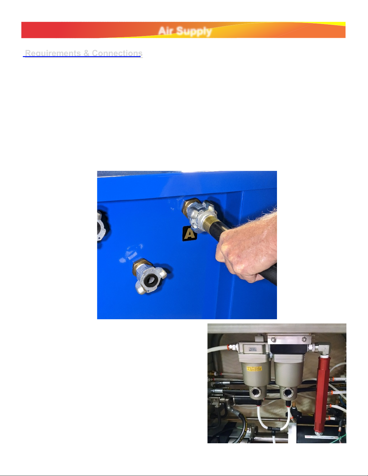
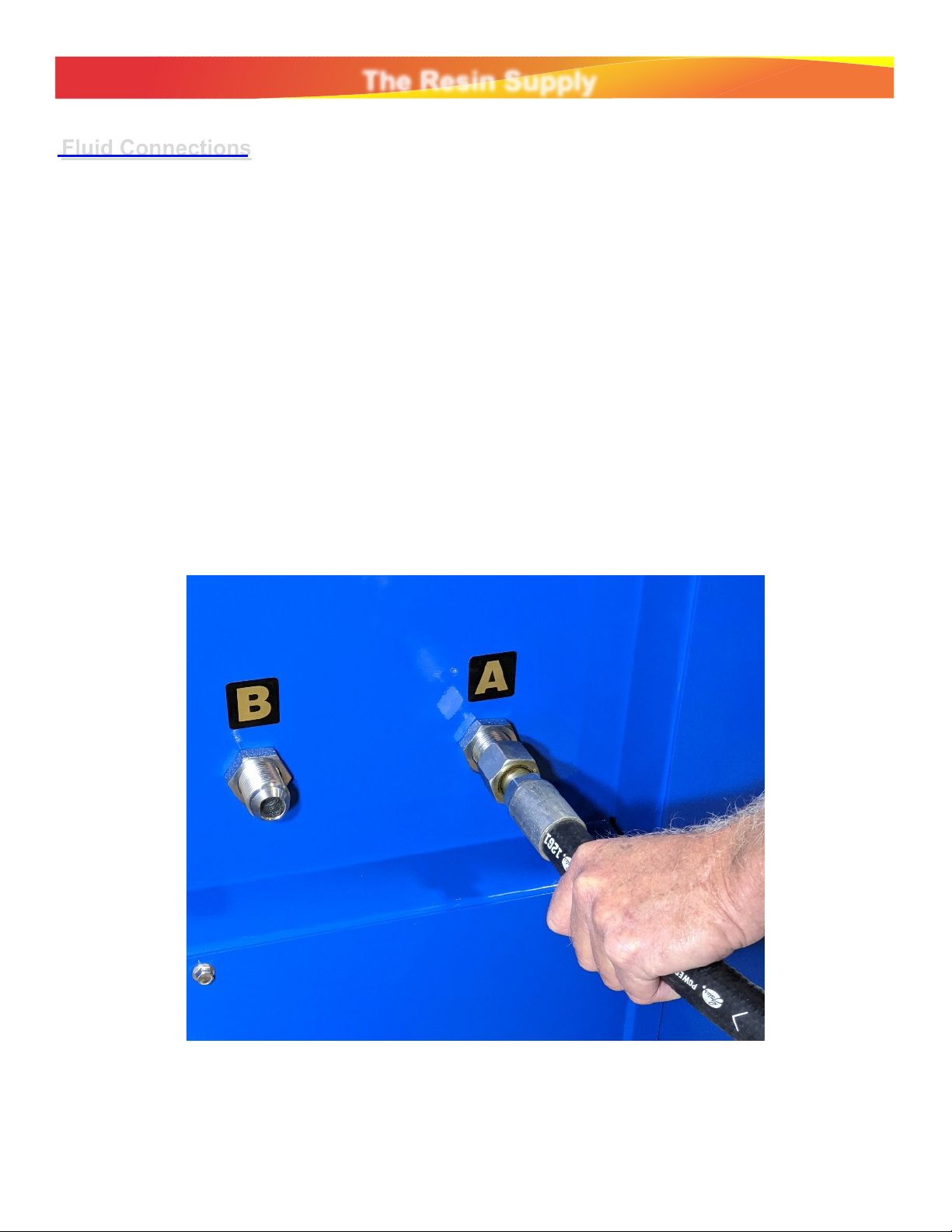
1. Start the ratio test with the air supply disconnected from the dispenser, the fluid lines from the
transfer pumps to the CD-200 connected, and the air lines from the transfer pumps to the CD-200
connected.
2. Make sure that the “ON/OFF” switch on the CD-200 is in the “OFF” position.
3. Make sure all the pressure regulators on the CD-200 are turned to Zero. You can do this by
turning the knob all the way to the left till the knob stops turning.
4. Disconnect the dispense hoses and allow the resin within the outlet fittings to drain.
5. Connect your air supply to the CD-200 dispenser and energize the air supply.
6. Slowly increase the air pressure to the transfer pumps to 80 psi.
7. Observe the outlet fittings for at least one minute for any signs of leakage. Depending on the
viscosity of the resin being dispensed it may take up to 15 minutes to see the flow of the resin to
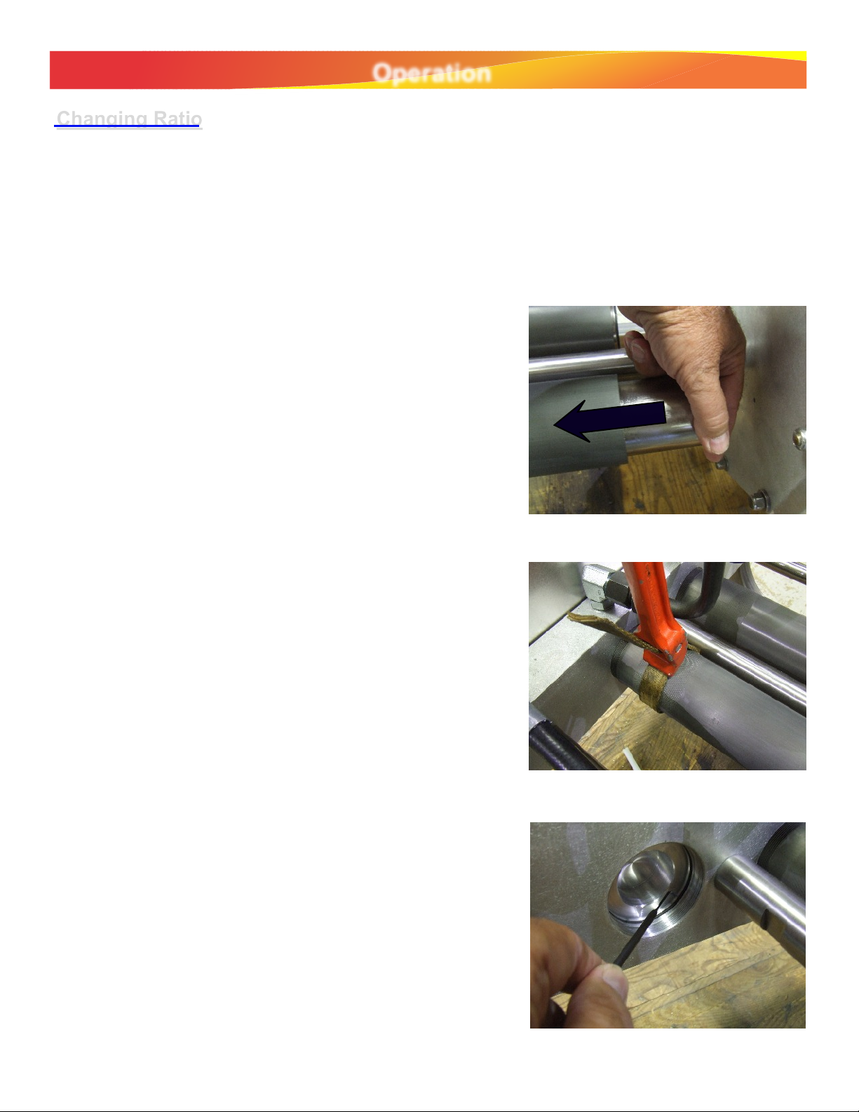
slow or stop. If the flow of resin does not stop then the ball valves will need to be rebuilt by
replacing the ball valve seals. If there is no leakage then proceed to the next step.
8. Reduce the pressure to the transfer pumps to “ZERO”.
9. Switch the Isolation Valve to the “Closed” (down) position. (The isolation valve is located inside
the cabinet mounted on the base manifold).
10.While holding a waste bucket over the outlet fittings, move the “ON/OFF” switch to the “ON”
position. WARNING! Hold this bucket firmly! When switching the “ON/OFF” there could be a
blast of air from the outlet fittings.
10.Slowly increase the “Dispenser” air pressure until the machine starts to dispense resin into the
waste bucket.
11.Once this dispense cycle is complete, wipe the dispense fittings clean and allow accumulated
resin within the fittings to drain. Observe the fittings for at least one minute. It could take up to 15
minutes depending on the viscosity of the resin for the flow of resin to stop. If the flow does not
stop or at least slow down, the ball valves will need to be rebuilt by replacing the ball valve seals.
If there is no leakage then this means that the ball valve seals are good and the machine is “On
Ratio”.
Operation
Ratio Assurance Test

8 Ver. 1.0
14.While holding a waste bucket under the outlet fittings again, Switch the isolation valve to the “Open”
position (Up).
15.Move the dispenser “ON/OFF” switch to the “OFF” position. The machine will return to the “Park” position.
16.Turn all of the pressure regulators back to “Zero”
17.Re-connect the dispense hoses and replace any covers that were removed for testing.
Caution: The above procedure is the only procedure that assures ratio accuracy for the CD-200. Random
volumetric comparisons taken at low pressures or high flow rates do not reveal the condition of the ball
valve seals. Only an extended and significant fluid pressure can accurately reflect their condition.
Operation
Ratio Assurance Test

9 Ver. 1.0
Operation
Ratio is determined by the relative diameters of the catalyst and base pistons. If the ratio is 1:1, both
metering pistons will be the same. However, with any other ratio, the catalyst metering piston will be
of a smaller diameter. Ratio is therefore changed by exchanging one catalyst metering assembly for
another. A metering assembly consists of a metering cylinder, a metering piston, and the seals, etc.
component to them. Metering assemblies for alternate ratios are available from Lily. A few simple
steps are required to change ratio:
1. De-energize the transfer pumps by turning their
respective regulators to “0 PSI”. With air connected to
the CD-200 Dispenser, turn the dispenser “Off”. This
will open the inlet ball valves and close the outlet valves
and send the main air cylinder to the “Park” position.
3. Disconnect the catalyst (B) supply hose from the
transfer pump. Grip the catalyst metering piston and
press it in until it is all the way into the metering cylinder
The material in the metering cylinder will be forced to
flow back through the inlet fitting. If the piston does not
go down easily, use a strap wrench to free it and twist it
as it is pressed in.
4. Use a strap wrench to turn the catalyst metering
assembly counter-clockwise until it is free. Do not
attempt to remove the assembly with any other tool
than a strap wrench, as the chamber may be damaged
by any uneven grasping force.
5. Use the seal pick to remove the base manifold o-
ring. Clean the pocket thoroughly and install a new o-
ring in the proper groove.
6. Important! Lubricate the threads of the replacement
metering assembly with an anti-seize compound or
silicone lubricant. Thread the assembly into the
manifold by turning it clockwise until it is seated. Do not
over-tighten. As the chamber bottoms out in the
manifold you will feel a definite stop. Do not tighten
further.
Changing Ratio
2. Remove the right and left side panels.

10 Ver. 1.0
SERVICING THE SYSTEM
If the CD-200 is properly maintained, service will involve little more than routine replacement of
dynamic seals
exposed to material being dispensed. The frequency of seal replacement will depend upon the
material dispensed. Thousands of gallons of non-abrasive resin with good lubricity may be dispensed
with little, if any,
service; while the use of an abrasive – and usually inexpensive – material is likely to necessitate
frequent seal
If the air supply is properly maintained, the system will deliver literally thousands of trouble-free
cycles. However, in the real world, that is not always possible. Therefore, periodic lubrication of the
air circuitry is recommended. To do so, deenergize the system and remove the right cover. Free the
four way air fitting (P-189) fixed to the bulkhead fitting (S-009) by pressing the collar of the elbow
down. Also disconnect the 1/4” tubing next to the four way air fitting. Squeeze a generous dose of
Lily Lube (P-315) into the rigid leg of the four-way fitting and the 1/4” tube. Reconnect the fitting and
tube. No other lubrication is needed. Never use WD-40 or similar products in the air circuit.
Disassembly
Make sure the dispenser switch is off and de-energize the transfer pumps. Disconnect the air supply
to the CD-200 and then remove the resin supply hoses from the rear of the dispenser. Remove both
side panels. Grasp the metering pistons and press them into their cylinders. This will purge the
cylinders of material, which will flow out of the fittings at the rear of the machine.Use a waste
container to catch this material. Then, follow the steps below:
1. Remove the fluid lines from the 3-way ball valve
2. Remove the 4 mounting bolts securing the ball valve to the
mounting bracket.
Lubrication
Ball Valve Seal Replacement
Note: Start this procedure with the CD-200 Dispenser in the “Park” or “OFF” position.
3. Remove the bolts mounting the bracket to the main frame
assembly.

11 Ver. 1.0
SERVICING THE SYSTEM
DISASSEMBLY cont”d
4. Loosen the set screws that secure the coupler to
the valve actuator shaft.
5. Now you can remove the ball valve from the
machine.
6. Remove the four bolts holding the ball valve
together.
7. Gently rotate the portion of the ball valve an inch
or so. Then, using a small pry bar, carefully pry up
the top portion of the ball valve body until it becomes
free from the main body. Now lift this part from the
main body.

12 Ver. 1.0
Disassembly
SERVICING THE SYSTEM
9. There are two O-ring seals associated with this
part. One of the seals is on the outer edge of the part
and consists of the O-ring and a white Teflon backer.
8. The other O-ring is in the inner diameter of the
part and also consists of an O-ring and a white
Teflon backer.
10. Remove the fluid fittings from the main valve
body. This will require a 1 5/16” wrench or preferably
a socket and an impact wrench. The main body will
need to be held firmly in a vice.

13 Ver. 1.0
SERVICING THE SYSTEM
11. With the main fittings removed, the ball (trunion) itself can
now be removed from the main valve body by pulling it up and
out.
Trunion
Bushing
12. There are two bushings in the ball valve. One is pictured
here. We have found that these phenolic bushings swell over
time and cause the ball valve to bind up. When rebuilding the
ball valve these should be replaced with brass bushings
supplied by Lily Corporation. The part #’s are S-353 and S-
354.
13. Remove and replace the O-ring at the fluid fittings. Be sure
that the white Teflon washer is sitting flat. It tends to curl
during installation.
14. The seal in the photo is the seal that presses against the
ball or trunion. If the ball valve fails the Ratio Test then this is
the seal that failed. These are hard to remove. If you look
inside the fitting itself you’ll see a small hole on the ID of the
fitting. If you can get to that hole with a small air tube
sometimes you can move the seal out by blowing air into the
small hole. Another way is to drill two small holes into the face
of the seal. Drill them 180 degrees apart from each other.
Don’t drill so deep that you hit the metal portion of the fitting.
Then screw two drywall screws into the holes. Pulling evenly
on the two screws while gently twisting them will pull the seal
out. Use caution when drilling these holes. If the fitting gets
damaged beyond use the only thing you can do next is to
replace the entire valve.
Disassembly

14 Ver. 1.0
SERVICING THE SYSTEM
The frequency of service will depend upon the abrasive content of the material being dispensed, and
to a lesser
degree, the abrasive atmosphere common to many construction sites. The need for metering
assembly service is
recognized by leakage between the metering piston and its cylinder, sluggish extension of the piston,
or by
seizure of the piston within the cylinder.
To remove a metering cylinder for service, turn the dispenser switch off, disconnect the air supply at
the dispenser, remove the side panels, disconnect the material supply hoses from the dispenser, and
follow the steps below:
1. Grasp the metering piston and press it into its cylinder,
thus purging the component back through the outlet
fittings. Be prepared to collect this fluid.
2. Loosen and remove the metering cylinder by rotating it
counterclockwise. Do not use a pipe wrench! Use a strap
wrench.
Metering Cylinders
3. Press the metering piston from the cylinder bore. If it’s
seized do not beat on the piston with a hammer to try to
get it out of the cylinder. Place the assembly in a hydraulic
press and slowly push the piston out of the cylinder. It
also helps to heat the cylinder to melt the epoxy that is
causing the piston to bind up. Be careful to not damage
the bore!
4. Clean the bore and piston thoroughly. Examine the cylinder. If it is scratched or otherwise
damaged, it must be replaced.
5. If the piston is scratched or marred, polish its surface with an abrasive cloth until no burr remains
to damage the metering cylinder.

15 Ver. 1.0
SERVICING THE SYSTEM
6. To replace the piston seal, remove the screw in the
cap
retaining the seal. Then remove the cap and the seal.
7.Replace the seals with their spring grooves away
from the piston.
8. Inspect the piston pad. If it is torn or worn,
replace it by removing its retaining screw. Apply a
drop of blue Loctite thread seal or equal to the
screw at reassembly.

16 Ver. 1.0
9. Lubricate the piston and chamber with silicone
grease and insert the piston pad end first into the
bottom (threaded end) of the metering cylinder.
10. Use the seal pick (P-457) to remove the
base manifold o-ring seal. Clean the pocket
thoroughly before installing a new seal.
11. Apply an an anti-seize compound to the
cylinder threads, and then screw it into the
manifold. Do not over tighten!
SERVICING THE SYSTEM
Important!

17 Ver. 1.0
Spurts of air, or air
bubbles in the material........... Check the material levels. The transfer pumps can draw air in if the fluid level
gets to low. Also check any fluid fittings on the suction side of the transfer
pumps that might be allowing air to be drawn in, especially the gaskets at the
cam-lock fittings.
Resin not setting up
Correctly……………………. Conduct ratio assurance check to confirm valve performance. (Page # 7)
Check compressibility of viscous components due to air being drawn into the
system.
Sluggish flow ...........................Disconnect the outlet fittings and observe the resin flow from the outlet ports. If
the flow is unrestricted, replace the mixer or other restriction in the exterior
plumbing. If the material is viscous (thick) due to chemistry or temperature you
can heat the material to reduce the viscosity and increase productivity.
Leakage of resin at
material pistons .......................Replace the piston seal(s). (Page # 14).
Metering piston fails
to extend, or extends
slowly ....................................... Disconnect the material inlet hose at the dispenser and check the flow from
the transfer pump. If the flow is restricted, check for an obstruction in the
material supply line, or insufficient delivery from the transfer pumps. If the
material supply is adequate, remove the Metering Assembly, and check for
freedom of piston movement within the cylinder. If the piston is seized or
binding, service the assembly. (Page # 14).
System begins to dispense,
but cannot complete a
dispense cycle .......................... Obstruction in material outlet lines or metering cylinder.
System is unresponsive ...........Check the air supply.
System does not make
dispense stroke. Audible
air leak at sensor ports. .......... Metering pistons not sealing off sensor ports due to worn or damaged pads.
Replace the pads. (Page #15, step 8). Insufficient material pressure to firmly
impinge the pads against the cap.
Main air cylinder return
is sluggish. ........….…………....Defective Rapid Exhaust valve (P-336).
Troubleshooting
TROUBLE SHOOTING

18 Ver. 1.0
TROUBLE SHOOTING
Main air cylinder fails to
return following full dispense
stroke.........................................Malfunctioning "End Of Stroke" valve (P-217). Check for proper
adjustment of valve. If valve adjustment is good replace valve. "Or"
valve (P-794) not functioning. Verify operation by turning On/Off
switch "Off". If the main air cylinder returns to the "Park" position then
replace "Or" valve.
Switch to “off” does not
return main air cylinder. .........”Or” valve not functioning. Remove the air line from the Or valve that
comes from the On/Off switch to verify the presence of air pressure.
If air pressure is present then connect the air line you removed back
to the Or valve and remove the output air line from the Or. If no air
pressure from the Or valve the replace the Or valve. If air pressure is
present then the Parker directional valve is not functioning. The
Parker directional valve can be disassembled and rebuilt. Call Lily for
seal kit for this valve.
If you cannot correct the problem,
contact Lily Corporation with an exact description of how the various components are
responding.
If possible, phone with the unit, air, tools, and resin information at hand.
Troubleshooting

19 Ver. 1.0
Parts Diagrams
CD-200 FRAME ASSY PARTS LIST
DESCRIPTION
PART NUMBER
QTY
ITEM
CD200 AIR CYLINDER SUPPORTS
M-28241
CD200 FRAME BASEM-28012
CD200 CORNER SUPPORTM-28143
CD200 HORIZONTAL SUPPORT - LONG
M-28334
CD200 BALL VALVE BRACKETM-2862
5
CD200 FRONT DASHBOARDM-28416
CD200 DASHBOARD REARM-28517
CD200 BALL VALVE SUPPORT
M-28718
CD200 HORIZONTAL SUPPORT - SHORT -
UPPER
M-28919
CD200 END PANEL (NOT SHOWN)
M-288210
CD200 SIDE PANELM-292211
CD200 LIDM-293112
1/4-20 RIV-NUTS-214
2016
3/8" FLAT WASHERP-1192517
3/8" LOCK WASHERP-076818
3/8-16 HEX NUTP-472820
3/8-16 -1 HEX BOLTS-056
1221
5/16-18 PREVAILING TORQUE HEX NUT
P-4774822
3/8-16 18 PREVAILING TORQUE HEX NUT
P-570423
5/16-18 - .75 CARRIAGE BOLTS-8834824
12
3
7
1
5
8
4
2
24
21
18
17
21
17

20 Ver. 1.0
Parts Diagrams
CD-200 DASHBOARD
DESCRIPTION
PART NUMBER
QTY
ITEM
PRESSURE REGULATORSP-97938
ON/OFF SWITCH
P-745121
3/4" JIC BULKHEAD FTGP-535424
COUNTER - ELECTRICP-299143
8
21
24
43
Table of contents
Other Lily Corporation Industrial Equipment manuals
Popular Industrial Equipment manuals by other brands

Kval
Kval 990-H Service manual

Afag
Afag WV401-1 Operating & installation instructions

R.V.R. Elettronica
R.V.R. Elettronica TEX20-NV Technical manual

WEDGELOCK
WEDGELOCK I-LOCK COUPLER installation manual

RS
RS COMPACT FREEZE TUNNEL Operation and maintenance manual

ELTRA
ELTRA AAM 58 B PROFINET installation instructions