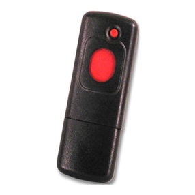
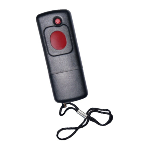
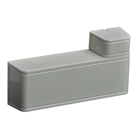
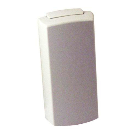
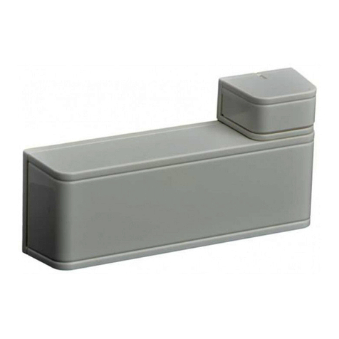
Bosch SEC-3402-304 User manual

Security Escort Point Tracking
Transmitter
SEC-3402 Series
en Installation Manual


Security Escort Point Tracking Transmitter Table of contents | en 3
Robert Bosch (SEA) Pte Ltd Installation Manual 2018.01 | SE3v1.0 | DL
Table of contents
1Copyright, Safety and Warranty 4
1.1 Copyright information 4
1.2 Important safety notes 5
1.3 Safety precautions 6
1.4 FCC/IC information 6
2System Overview 7
2.1 Supervision 7
2.2 Auto-tracking 7
3Installation and Setup 8
3.1 Mounting the point transmitter 8
3.1.1 Recommended mounting 8
3.1.2 Mounting without the mounting plate 10
3.1.3 Mounting the magnet 10
3.2 Powering up the point transmitter 11
3.2.1 3V battery 11
3.2.2 12 VDC input 12
3.3 Setting up magnetic or external contacts 12
4Enabling and Disabling Features 14
4.1 Default dip switch setting 14
4.2 Setting the radio frequency (RF) 14
4.3 Enable/disable the auto-track 15
4.4 Enable/disable the displacement detection 15
4.5 Enable/disable the reed switch 15
4.6 Enable/disable the buzzer 16
4.7 Factory reset 16
4.8 System programming 16
4.9 Configuring the transmitter 17
4.10 Testing the transmitter 17
5Upgrading Transmitter Firmware 18

4en | Copyright, Safety and Warranty Security Escort Point Tracking Transmitter
2018.01 | SE3v1.0 | DL Installation Manual Robert Bosch (SEA) Pte Ltd
1 Copyright, Safety and Warranty
1.1 Copyright information
All rights reserved. No part of this manual may be reproduced, stored in a retrieval system, or
transmitted in any form or by any means, electronic, mechanical, photocopying, recording, or
otherwise, without the prior written permission of BOSCH SECURITY SYSTEMS.
This manual is provided pursuant to a license agreement containing restrictions on their use.
The manual contains valuable trade secrets and proprietary information of BOSCH SECURITY
SYSTEMS and is protected by international copyright law. It may not be copied or distributed
to third parties, or used in any manner not provided for in the said license agreement.
All software is provided "AS IS." The sole obligation of BOSCH SECURITY SYSTEMS shall be to
make available all published modifications that correct program problems are published within
one (1) year from the date of shipment.
The software is intended for use only with the hardware specified in this manual and in the
absence of other software. Concurrent use with other software or with hardware not specified
may cause the program to function improperly or not at all. BOSCH SECURITY SYSTEMS may
not provide support for systems operating under such conditions.
All efforts have been made to ensure the accuracy of the contents of this manual. The above
notwithstanding, BOSCH SECURITY SYSTEMS assume no responsibility for any errors in this
manual or their consequences.
The information on this document is subject to change without notice.
Other product and company names mentioned herein may be the trademarks of their
respective owners.

Security Escort Point Tracking Transmitter Copyright, Safety and Warranty | en 5
Robert Bosch (SEA) Pte Ltd Installation Manual 2018.01 | SE3v1.0 | DL
1.2 Important safety notes
1. Read, Follow, and Retain Instructions – All safety and operating instructions must be
read and followed properly before putting the unit into operation. Retain instructions for
future reference.
2. Consider all Warnings – Adhere to all warnings on the unit and in the operating
instructions.
3. Accessories – Use only accessories recommended by the manufacturer or those sold
with the product. Accessories not recommended by the manufacturer shall not be used,
as they may cause hazards.
4. Installation Precautions – Do not place this unit on an unstable stand, tripod, bracket, or
mount. The unit may fall, causing serious injury to persons and damage to the unit. Mount
the unit according to the manufacturer’s instructions.
5. Service – Do not attempt to service this unit by yourself. Opening or removing covers may
expose you to dangerous voltages or other hazards. Refer all servicing to qualified service
personnel.
6. Damage Requiring Service – Disconnect the unit from the main AC or DC power source
and refer servicing to qualified service personnel under the following conditions:
– When the power supply cord or plug is damaged.
– If liquid has been spilled or an object has fallen into the unit.
– If the unit has been exposed to water and/or inclement weather (rain, snow, etc.).
– If the unit does not operate normally, when following the operating instructions.
Adjust only those controls specified in the operating instructions. Improper
adjustment of other controls may result in damage, and require extensive work by a
qualified technician to restore the unit to normal operation.
– If the unit has been dropped or the cabinet damaged.
– If the unit exhibits a distinct change in performance, this indicates that service is
needed.
7. Replacement Parts – When replacement parts are required, the service technician shall
use replacement parts that are specified by the manufacturer. Unauthorized substitutions
may result in fire, electrical shock or other hazards.
8. Safety Check – Upon completion of service or repair work on the unit, ask the service
technician to perform safety checks to ensure that the unit operates properly.
9. Power Sources – Operate the unit only from the type of power source indicated on the
label. If unsure of the type of power supply to use, contact your dealer.
– For units intended to operate from battery power, refer to the operating instructions.
– For units intended to operate with External Power Supplies, use only the
recommended approved power supplies.
10. Lightning – For added protection during a lightning storm, or when this unit is left
unused for long periods of time, disconnect the unit from power. This will prevent
damage to the unit due to lightning and excessive power line surges.
11. Restricted Access Locations are required for the installation.
6en | Copyright, Safety and Warranty Security Escort Point Tracking Transmitter
2018.01 | SE3v1.0 | DL Installation Manual Robert Bosch (SEA) Pte Ltd
1.3 Safety precautions
Disposal
Your Bosch product has been developed and manufactured using high-
quality materials and components that can be reused.
This symbol means that electronic and electrical devices that have reached
the end of their working life must be disposed of separately from
household waste.
In the EU, separate collecting systems are already in place for used
electrical and electronic products. Please dispose of these devices at your
local communal waste collection point or at a recycling center.
1.4 FCC/IC information
This device complies with Part 15 FCC Rules and Industry Canada's license-exempt RSSs.
Operation is subject to the following two conditions: (1) this device may not cause harmful
interference, and (2) this device must accept any interference received including interference
that may cause undesired operation.
Changes or modifications not expressly approved by the party responsible for compliance
could void the user’s authority to operate the equipment.
This equipment has been tested and found to comply with the limits for a Class B digital
device, pursuant to Part 15 of the FCC Rules. These limits are designed to provide reasonable
protection against harmful interference in a residential installation. This equipment generates,
uses and can radiate radio frequency energy and, if not installed and used in accordance with
the instructions, may cause harmful interference to radio communications. However, there is
no guarantee that interference will not occur in a particular installation.
If this equipment does cause harmful interference to radio or television reception, which can
be determined by turning the equipment off and on, the user is encouraged to try to correct
the interference by one or more of the following measures:
1. Reorient or relocate the receiving antenna.
2. Increase the separation between the equipment and receiver.
3. Connect the equipment into an outlet on a circuit different from that to which the
receiver is connected.
4. Consult the dealer or an experienced radio/TV technician for help.
Notice!
The FCC label can be found under the enclosure cover once you open up the SEC-3402 series
transmitter enclosure.

Security Escort Point Tracking Transmitter System Overview | en 7
Robert Bosch (SEA) Pte Ltd Installation Manual 2018.01 | SE3v1.0 | DL
2 System Overview
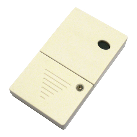
The SEC-3402 series point transmitter is a magnetic and dry contact wireless transmitter used
for monitoring assets.
The unit is equipped with an internal reed contact for use with an external magnet assembly
(included), a cover tamper switch, a displacement detector, a buzzer and RF supervision. The
SEC-3402 series can accept a supervised dry contact input from an external device.
The transmitter is available in the following models:
Transmitter Model Description
SEC-3402-304 Point tracking transmitter, 303/304MHz
SEC-3402-433 Point tracking transmitter, 433MHz
2.1 Supervision
Supervision is provided by transmitting a low power level signal to the receiver every 60 min if
there is no other activity. SEC-3402 series send battery status information to the system.
2.2 Auto-tracking
Once an alarm is initiated, such as the transmitter moved away from the magnet, the auto
tracking feature begins. The transmitter sends a signal back to the central console every 7
seconds, updating its location for 15 minutes. To reset the transmitter after an alarm has been
initiated, all device conditions (such as tamper, loop, or magnet) must be reset to normal.

8en | Installation and Setup Security Escort Point Tracking Transmitter
2018.01 | SE3v1.0 | DL Installation Manual Robert Bosch (SEA) Pte Ltd
3 Installation and Setup
This section provides information for system planners and configurators.
3.1 Mounting the point transmitter
Notice!
Avoid mounting the point transmitter on metal surfaces as it can reduce the range of the unit.
Placing the point transmitter on ferrous metal (iron or steel) surfaces can affect operation of
the magnetic contact.
3.1.1 Recommended mounting
1. Position the mounting plate over the desired location and attach it with the supplied
screws.
Figure3.1: Attach mounting plate
1 Release tab 2 Mounting holes
2. Open the cover using a screwdriver.
Figure3.2: Open cover
1 Insert screwdriver and press here 2 Push in
3. Be sure to note the location of the magnet when mounting the base.
4. Slide the point transmitter over the base to lock it into place.

Security Escort Point Tracking Transmitter Installation and Setup | en 9
Robert Bosch (SEA) Pte Ltd Installation Manual 2018.01 | SE3v1.0 | DL
Figure3.3: Slide point transmitter over base
5. The point transmitter can be released from the base by pressing the release tab with a
small screwdriver or a paper clip.
6. For higher security installations, mount the transmitter using the tamper screw provided.
Figure3.4: Mount transmitter using tamper screw
1 Tamper screw

10 en | Installation and Setup Security Escort Point Tracking Transmitter
2018.01 | SE3v1.0 | DL Installation Manual Robert Bosch (SEA) Pte Ltd
3.1.2 Mounting without the mounting plate
1. If the battery was installed in the point transmitter, remove it at this time.
2. Using a small screwdriver, gently lift the printed circuit board away from the case
mounting clips. You do not need to remove the cover to remove the board.
Figure3.5: Lift printed circuit board
3. Rock the board gently to loosen the battery clips from the case and slide the board away
from the mounting clips near the area where the cover connects to the base.
4. Mount the point transmitter in the desired location, taking note the magnet needs to be
on the same side of the case as the reed switch.
Figure3.6: Mount point transmitter in desired position
1 Magnet side 2 Mounting holes
3.1.3 Mounting the magnet
Mount the magnet as shown in the following figure. The magnet must mount within 19 mm
(0.75 in.) of the base of the unit.

Security Escort Point Tracking Transmitter Installation and Setup | en 11
Robert Bosch (SEA) Pte Ltd Installation Manual 2018.01 | SE3v1.0 | DL
Figure3.7: Mount the magnet
1 End view from the opening end
3.2 Powering up the point transmitter
The SEC-3402 series can be powered up either by 3V battery or 12 VDC input, depending on
the setting of the jumper.
3.2.1 3V battery
1. Check that the jumper is set over the jumper pins marked by the symbol. This is the
default factory setting on the point transmitter.
2. Install the recommended type of battery: Duracell® DL123A, Energizer® EL123AP or
Panasonic® CR123A. Be sure to observe the polarity.
Figure3.8: Install battery
1 Jumper setting 2 Battery

12 en | Installation and Setup Security Escort Point Tracking Transmitter
2018.01 | SE3v1.0 | DL Installation Manual Robert Bosch (SEA) Pte Ltd
3.2.2 12 VDC input
1. Set the jumper over the jumper pins as illustrated in the diagram below.
2. Connect the 12 VDC source to the connector of the transmitter.
Figure3.9: 12 VDC input
1 Jumper setting 2 12 VDC in
3.3 Setting up magnetic or external contacts
The SEC-3402 series has the capacity to monitor magnetic and/or dry external contacts.
External Normally Closed (NC) or external Normally Open (NO) contacts can be monitored.
Recommended cable: 18 AWG < 20 ft (6 m)
EOL resistor: 1 Mega ohms
Notice!
If not using external contacts, you must install the EOL resistor.

Security Escort Point Tracking Transmitter Installation and Setup | en 13
Robert Bosch (SEA) Pte Ltd Installation Manual 2018.01 | SE3v1.0 | DL
Figure3.10: Magnet (optional) typical NC wiring
1 Magnet bar 2 EOL resistor
Figure3.11: Magnet (optional) typical NO wiring
1 EOL resistor

14 en | Enabling and Disabling Features Security Escort Point Tracking Transmitter
2018.01 | SE3v1.0 | DL Installation Manual Robert Bosch (SEA) Pte Ltd
4 Enabling and Disabling Features
The features of SEC-3402 series can be set, enabled or disabled accordingly using its dip
switch. There are 6 switches on the dip switch. Usage of the dip switch is explained as of
below:
Switch Number Usage
1 Frequency Selection:
OFF - 304 MHz (default setting)
ON - 303.825 MHz
(Not applicable to SEC-3402-433)
2 Auto-track (every 7 seconds)
3 Displacement Detection
4 Reed Switch
5 Buzzer
6 Not Used
Notice!
Remove the battery before setting the dip switches. Changes to the dip switches should be
performed by administrators only.
4.1 Default dip switch setting
The default setting of the SEC-3402 series dip switch is as follows:
Default Setting Switch Number on Dip Switch
1 2 3 4 5 6
(not used)
Switch
Position
OFF OFF OFF OFF OFF OFF
4.2 Setting the radio frequency (RF)
Set switch number 1 on the dip switch to configure the RF of the device. This setting is not
applicable for the SEC-3402-433 model as its RF is fixed as 433 MHz. The following settings
are configurable for the SEC-3402-304 model.

Security Escort Point Tracking Transmitter Enabling and Disabling Features | en 15
Robert Bosch (SEA) Pte Ltd Installation Manual 2018.01 | SE3v1.0 | DL
Radio Frequency Switch Number on Dip Switch
1
304 MHz (default setting) OFF
303.825 MHz ON
Tab.4.1: Radio frequency (RF) settings on dip switch
4.3 Enable/disable the auto-track
Enable or disable the auto-track feature by setting switch number 2 on the dip switch. Set
switch number 2 to the OFF position to disable the auto-track feature. Set switch number 2 to
the ON position to enable the auto-track feature. Once enabled, an alarm will trigger the
transmitter to send a signal back to the Central Console every 7 seconds for a period of 15
minutes.
Auto-track Feature (7 seconds) Switch Number on Dip Switch
2
Disable (default setting) OFF
Enable ON
Tab.4.2: Auto-track setting on dip switch
4.4 Enable/disable the displacement detection
Enable or disable the displacement detection feature by setting switch number 3 on the dip
switch. Set switch number 3 to the OFF position to disable the displacement detection
feature. Set switch number 3 on the dip switch to the ON position to enable the displacement
detection feature. Once enabled, any movements of the transmitter will send a signal back to
the Central Console.
Displacement Detection Feature Switch Number on Dip Switch
3
Disable (default setting) OFF
Enable ON
Tab.4.3: Displacement detection setting on dip switch
4.5 Enable/disable the reed switch
Enable or disable the reed switch feature by setting switch number 4 on the dip switch. Set
switch number 4 to the OFF position to disable the reed switch feature. Set switch number 4
to the ON position to enable the reed switch feature. Once enabled, the transmitter would be
able to detect the state of the attached electromagnetic circuitry.
Reed Switch Feature Switch Number on Dip Switch
4
Disable (default setting) OFF
Enable ON
Tab.4.4: Reed switch setting on dip switch

16 en | Enabling and Disabling Features Security Escort Point Tracking Transmitter
2018.01 | SE3v1.0 | DL Installation Manual Robert Bosch (SEA) Pte Ltd
4.6 Enable/disable the buzzer
Enable or disable the buzzer feature by setting switch number 5 on the dip switch. Set switch
number 5 to the OFF position to disable the buzzer feature. Set switch number 5 to the ON
position to enable the buzzer feature. Once enabled, the buzzer would sound when an alarm is
triggered and with every auto-track transmission.
Buzzer Feature Switch Number on Dip Switch
5
Disable (default setting) OFF
Enable ON
Tab.4.5: Buzzer setting on dip switch
4.7 Factory reset
Factory reset should be performed by administrators only. Set all the dip switches to the
OFF position. While pressing the Test button, the transmitter resets after inserting the battery.
If reset is successful, there will be 3 slow consecutive beep tones every 1 second. If reset is
unsuccessful, there will be 2 slow consecutive beep tones every 1 second. Refer to the
following list of values that are being set for the respective features following the factory
reset.
Default Setting
Feature Value
Supervision Tracking Interval 60 minutes
4.8 System programming
A two part ID sticker is located on the enclosure. You need the number on this sticker to
program this device into the system. See the Security Escort Technical Reference Manual for
programming information for wireless type devices.

Security Escort Point Tracking Transmitter Enabling and Disabling Features | en 17
Robert Bosch (SEA) Pte Ltd Installation Manual 2018.01 | SE3v1.0 | DL
1 ID number
4.9 Configuring the transmitter
Notice!
Please note that this feature is only applicable to SEC-3402-433 transmitter model!
All factory reset features can be configured wirelessly on the transmitter via the coordinator/
receiver using the Central Console software. Enroll transmitter to the Central Console
software before configuration. Using the Central Console software, enable or disable the
features accordingly and send the configuration to the transmitter. Please refer to the Security
Escort Technical Reference Manual for further details.
4.10 Testing the transmitter
Test your transmitter by standing within sight of a receiver. Press the Test button for 3
seconds until the transmitter emits 3 short beep tones. A test transmission is sent to the
Central Console, lighting the green LED on a receiver or the strobe on an outdoor siren-strobe.
There might be a brief delay of 2 to 3 seconds before the flashing light appears. A successful
test transmission will light up the green LED on a receiver; retest if otherwise.

18 en | Upgrading Transmitter Firmware Security Escort Point Tracking Transmitter
2018.01 | SE3v1.0 | DL Installation Manual Robert Bosch (SEA) Pte Ltd
5 Upgrading Transmitter Firmware
Notice!
Please note that this feature is only applicable to SEC-3402-433 transmitter model!
Transmitter firmware can be upgraded wirelessly via a dedicated coordinator using the Utility
Tool of the Security Escort software. For more information on the usage of Utility Tool, please
refer to the Security Escort Technical Reference Manual.


Bosch Sicherheitssysteme GmbH
Robert-Bosch-Ring 5
85630 Grasbrunn
Germany
www.boschsecurity.com
© Bosch Sicherheitssysteme GmbH, 2018
Robert Bosch (SEA) Pte Ltd
11 Bishan Street 21
573943 Singapore
Singapore
This manual suits for next models
4
Table of contents
Other Bosch Transmitter manuals

Bosch
Bosch SE88A-90S-304 User manual

Bosch
Bosch Security Systems SE2 Series Manual

Bosch
Bosch SE88 User manual

Bosch
Bosch S35 User manual

Bosch
Bosch SEC-RFPB60M-433 User manual

Bosch
Bosch EN1210 Series User manual

Bosch
Bosch ISW-EN1210 Manual

Bosch
Bosch CRS-SB-424FI User manual

Bosch
Bosch CRS-RM-905FI User manual

Bosch
Bosch CRS-SB-423FI User manual

Bosch
Bosch RF3401E User manual

Bosch
Bosch ISW-EN1265 User manual

Bosch
Bosch ISW-EN1233 User manual

Bosch
Bosch CRS-NC-S37L User manual

Bosch
Bosch MIYN46 User manual

Bosch
Bosch ISN-GMX-S1 User manual

Bosch
Bosch RF3401E User manual

Bosch
Bosch NurseCall N46 User manual

Bosch
Bosch RF3503E User manual

Bosch
Bosch ISW-EN1261HT User manual