2-12 | Page
1.5 Unauthorised Modification
Modifications of or other technical alterations to the
instrument by the customer are not permitted. This
also applies to replacement parts. Any modifica-
tions / alterations required shall be carried out by
Fischer Mess- und Regeltechnik GmbH only.
1.6 Inadmissible Modes of Operation
The operational safety of this instrument can only
be guaranteed if it is used as intended. The instru-
ment model must be suitable for the medium used
in the system. The limit values given in the technical
data may not be exceeded.
1.7 Safe working practices for
maintenance and installation work
The safety instructions given in this operating man-
ual, any nationally applicable regulations on acci-
dent prevention and any of the operating company's
internal work, operating and safety guidelines must
be observed.
The operating company is responsible for ensuring
that all required maintenance, inspection and instal-
lation work is carried out by qualified specialized
personnel.
1.8 Symbol explanation
WARNING!
… indicates a potentially dangerous
situation, non-observance of which
could endanger persons, animals, the
environment or objects.
INFORMATION!
… highlights important information for
efficient and smooth operation.
TIP!
… indicates recommendations that are
not specifically necessary in certain
situations but which could be useful.
2 Application purpose
Measuring transducer and switching device for
over-pressure, under-pressure and differential
pressure of gaseous media. It may only be used for
the intended use given in the manufacturer's data
sheet. If any soiled or aggressive media is expected
on the system side, the instrument needs to be
modified in terms of those parts that have contact
with the medium. Talk to the manufacturer before
ordering.
3 Description of the product and func-
tional description
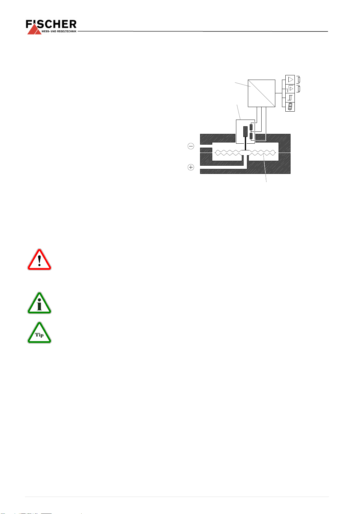
3.1 Functional Schematic
3.2 Design and mode of action
The base of the measuring and switching instru-
ment DE 50 is a diaphragm capsule measuring sys-
tem that is suitable for measuring overpressure,
under-pressure and differential pressure. The pres-
sure or differential pressure that is to be measured
triggers the diaphragm capsule, thereby moving the
core of the inductive displacement transducer. This
is converted to an electrical output signal in the
downstream electronics. The transformer electron-
ics are available in several models.
In addition to the various operating voltages, the
output signal can be designed as a current or volt-
age signal.
Flows in gaseous media are often measured ac-
cording to the effective pressure principle. To
achieve a flow-proportional measured value, the ef-
fective pressure signal needs to be rooted. There
are transformer electronics available to supply the
rooted output signals for these applications.
In addition to the analogue output signal, the in-
strument can be equipped with potential-free con-
tact outputs that can be set to each value within the
measuring range.
The pressure / differential pressure values can be
displayed as linear measured values on site via an
installed LC display (optional).
4 Installation and assembly
The instrument can be installed on even walls, as-
sembly plates or switch cabinet assembly rails. The
four attachment boreholes are accessible after the
lid has been removed from the instrument.
At the factory, the device is calibrated for vertical
installation, but the installation position is arbitrary.
For any installation positions that are not vertical,
Inductive displacement
transducer


