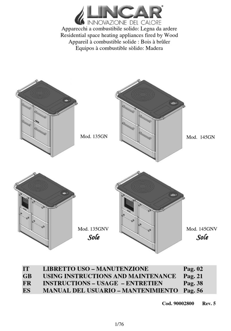
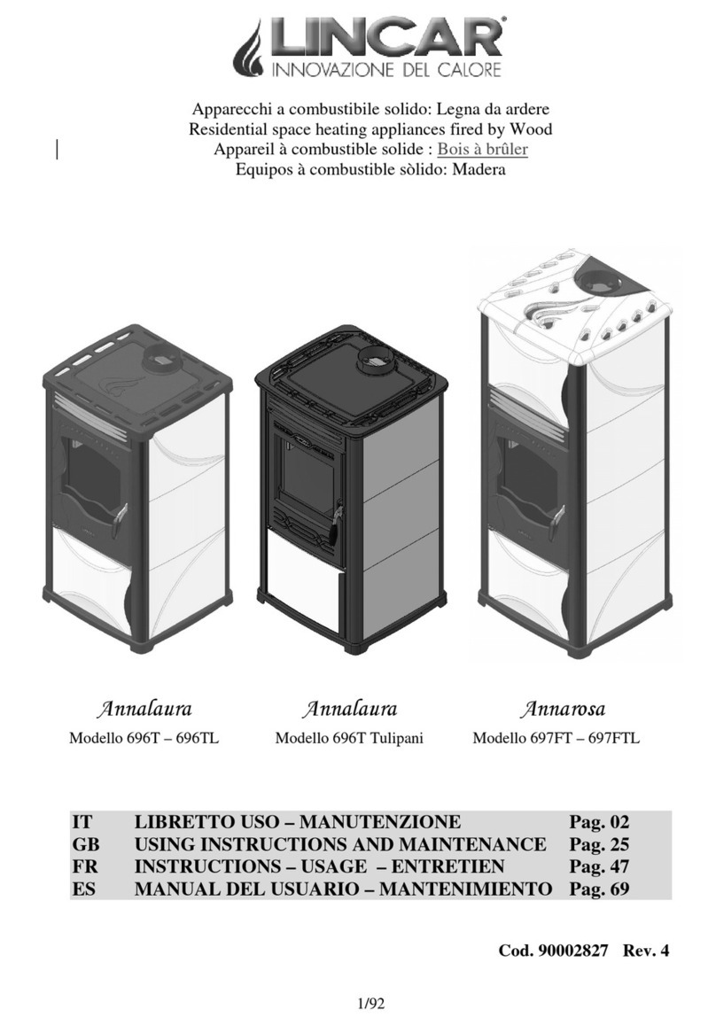
Lincar 135GN Guide

Residential spaceheating appliancesfiredby:Wood
1/20
Mod. 135GN
Mod. 145GN
USINGINSTRUCTIONS AND MAINTENANCE
Equipmentsbuiltin conformity withEuropean Normsfor marking
Cod. 90003018 Rev. 2

mo d. 1 35 GN-145GN GB
2/20
Dear Customer,
While we thank you for t h e p reference you grant ed u s, we remin d you to read
carefullythepresent handbookbecauseit gives Youimportant warnings with
particular attention t o the inst allation, utili zation, maintenance and to the security of
the product in addition to condition of guarantee . To avoid it will be considered “
IMPROPER USE” of the equipment and therefore“UNCORRECTLY
UTILIZATION” with possibly ofdecay oftheguarantee.
.
INDEX
Chap. Description Pag.
1 Installation 3
1.1 Normative andprescriptions 3
1.2 Preliminary operations 3
1.3 App l ian ce posi ti on in g 3
1.4 Connection 5
1.5 Technical details 9
2 Using
10
2.1 Important warnings 10
2.2 Combustible 10
2.3 Starting 11
3 Maintenance and cleaning 15
3.1 Ordinary maintenance 15
3.2 Extraordinary maintenance 17
3.3 Accessories 17
3.4 Possible failure and its solution 18
4Technical data plate 20

mo d. 135GN-145 GN GB
3/20
1INSTALLATION
RESERVED TO INSTALLER
1.1 Normative and prescriptions
•Read carefully the contents of this handbook, it contains important information and
instructions for installation, use, maintenance and product safety.
•The appliance must be installed inside an environment considered suitable for installation
and use by competent authorities. All laws, standards and regulations in force on the
installation site must be observed, especially regarding fire prevention.
•Technological connection and appliance installation must be carried out by qualify staff
authorized to release a conformity certificate according with the normative in force and
current standards.
•All the normative concerning civil town planning and/or industrial in force must be
respected inside the environment of installation of the appliance. In every case the safety
devices shou ld b e alw ays emp l oy ed .
•The installation must be carried out and certified according to the normative in force
regarding installations, exhaust fumes connections, electricity, water, ventilation /
suction.
•The manufacturer disclaims all responsibility caused by no correct installation,
using, tampering, maintenanceor no respectof normative inforce.
1.2 Preliminary operations
•Take away the packing.
•Before i n st all ati on , ch eck the appli an ce in t eg rit y . In case o f d ou bt , do n ot use th e
appliance and call the dealer.
•Packing materials is for recycle, getting it in thespecify container.
1.3 Appliance positioning
•The installation environment should have :
−A suitable floor for appliance weight and calorific radiation, otherwise preventive
measures should be adopted. (Ex. P late for charge distribution ).
−A suitable floor for appliance calorific radiation to guarantee the building against
any fire risk.
−The applianceshould beinstalled so that gas flue, chimney and cleaning could be
easily done.
−A minimal distance from fla mmable materials ( Security Distances)
−A suitable ventilation as normative in force
FLOOR PROTECTION
•The equipment has to be put on a refractory surface. In case of flammable floor
( carpet, parquet ..) it’s necessary to put a refractory base( stainless steel, ceramic etc )
with the following dimensions :
−Hold up in front ≥500 mm;
−Hold up lateral ≥300 mm;
−Hold up back ≥100 mm.

mo d. 135GN-145 GN GB
4/20
T o measure from extern al side of
the equipment
SECURITYDISTANCES
•From flammable object :
−A > 400 mm B > 175 mm C > 200 mm
•From flammable object and fromprincipal wall in rein forced concrete :
−A > 800 mm B >350 mm C > 400 mm
•The minimal distance between the appliance and every flammable object around it is 1.5
met er .
These are the measures in mm o f different
equipments models.

mo d. 135GN-145 GN GB
5/20
Fig. 3
Fig. 1
Fig. 2
1.4 Connection
•Before connection check technical data reported in the technical plate ( Chap. 4 ) and
control t h at it co rresp on d to th e on es requ i red in t h e o rd er.
•All heating biomass equipment especially wood appliance has to evacuate the combustion
products in a flue built in conformity with normative in force.
•The following instructions describes „ informations for a good installation „ and it refers
to a normative in force but it are not to be consider exhaustive for installations laws.
COLLAR EXHAUSTFUMESASSEMBLY Fig.1
Place the collar over the plate into special place.
HANDRAILASSEMBLING Fig.2
To insert the caps “ D” on terminals
su pp ort “ C”.
To insert the support“C” in tube“A”
than fix it to the plate frame with
screws“ F”interposing the connection
ring “ B”.
TOP ASSEMBLING Fig.3
•To take the top out ofwood drawer
•To put the top over wood cooker plate, insert
the toppin into the right holes on plate frame
than screw it and tighten.
Exhaust fumes collar

mo d. 135GN-145 GN GB
6/20
CHIMNEYOR FLUE
•The chimney or flue should havethe following characteristics:
−It’ s advisable read, follow and respect what indicated in the paragraphe 1.1
−Good sel of combustion products, impermeable and completely insulated as
normative condiction
−The flue has to be built with raw material suitable for normal mechanical stress,
warmth, action ofcombustion products and its condenses.
−The flow has to be vertical with deflections no hihgher that 45°.
−A right distance from co mbustible or flammable material, insulated with an air
cavity o r ri gh t in su l at o r.
−Internal round section, the square or rectangular section should have round corner
with a ray notless than 20 mm.
−Internal section should be constant, free and indipendent.
−Rectangluar section with sides ration max of 1,5 .
−All manufacturer instruction should be respected concerning the section and the
building characteristic of the chimney or flue. For particular section, deviation of
section or path it will be necessary a complete inspection ofexhaust fumes system.
−It‘ s advisable that the flue should be supplied by a „ chamber „ for solid material and
condenses collection, placed under the flue throat and easy to reach and to open. It
should be also supplied by a completely seal„little door“ for inspection.
−In case of fire of chimney or flue, employ the right system to soffocate the flames
an d c all fo r fi r e fi g h t er .
EQUIPMENT CONNECTION TO CHIMNEYFLUE ANDEXHAUSTCOMBUSTION
PRODUCTS
•It’ s advisable to read, follow and respect what indicated in the paragraphe 1.1
•The flue should receive the exhaust fumes fro man only heating equipment.
•It’s possible to realise an equipment composed from chimney and cooking oven with an
only exhaust fumes point head the chimney, for which the manufactures has to provide
the building characteristics of exhaust fumes channel.
•It’s prohibited to connect in the same flue, the heating equipment and the suction hood.
•It’ s prohibited to connect the exhaust pipe head closed space even if it is in open air.
•The direct exhaust fumes has to be done ahead roof and the exhaust pipe should have the
above characteristics.
CHIMNEYCAP
•The chimney cap should have the following characteristics:
−It’ s advisable to read, follow and respect what indicated in the paragraphe 1.1
−Internal section equivalent with the chimney one.
−Exhaust section exit not lower to the double ofthe chimney internal one.
−Built in a way to avoid rain, snow or external body entrance, to ensure the right exit
ofcombustionproducts with any type ofwind.
−Positioned to guarantee the right fumes dispersion especially ou of re-flux area. This
area has several dimensions and conformations in function of inclination corner of
the covering so it’s necessary to apply the minimal highness as indicated in the
following tables:

mo d. 135GN-145 GN GB
7/20
Inclination Roof
C(°) A H Re Flux Area Highness Z(m)
15 1,85 1,00 0,50
30 1,50 1,30 0,80
45 1,30 2,00 1,50
60 1,20 2,50 2,10
Re-flux
a
r
ea
Chimney pot
wind damping
Chimney
Pot Wind
Damping
Revolving
chimney pot
for strong
horizontal
wind

mo d. 135GN-145 GN GB
8/20
CONNECTION TO FLUE
•The connect the heating equipment to the flue / chimney checking that the exhaust pipe
don’t take up the free section offlue.
•Employ only tubes supplied by seal gasket.
•To not use horizontaltubes ( max1 meter ) and curves.
FEEDAIR COMBUSTION DIRECTFROMENVIRONMENT
•It’ s advisable to read, follow and respect what indicated in the paragraphe 1.1
•The eq uipment sh ou ld h av e t h e n eces s ary ai r fo r co mb us ti on , supp li ed by ext ern al ai r
intake.
•The air intake should have the following characteristics :
a) Total free section min 200 cm²;
b) Connected directly with installation environment ;
c) Protected with grate or lath ( attention to not reduce the min. section required on
point a) and placed so that to avoid obstruction.
•The air inflow can be also supplied from the adjacent room but the air intake should be
always free and connecter ahead outside. No chimney or suction hood should be present
in the environment ofinstallation orinto the nears ones.
•Inside the adjacent room the air intake should have the characteristics required in letter a
and c .
•The adjacent room can not be use as garage, warehouse ofcombustible material etc.
NOTE : Extractor fans when operating in thesameroom or spaceas theappliancemaycause
problems.
NOTE :The installation room should not be put in depression by other appliances such as
suction hoods, chimneys, evacuation flues, present in the room itself or in the adjacent rooms,
which arein communication.

mo d. 135GN-145 GN GB
9/20
1.5 Technical Details
Description Mod. 135GN 145GN
Width mm 880 980
Depth mm 570 620
Height mm 850 850
Appliance weight kg 85 109
Exhaust Fume Ø mm 120 130
Max. termic power output kW 9.6 11.0
Nominal heat output kW 6.5 8.0
Emissions ofCO : (to 13% O2) % 0.330 0.320
Efficiency : % 68.0 73.0
Heating volume (favourable insulation) m3 165 200
Heating volume (unfavourable insulation) m3 85 105
Flue gas temperature: Medium- Max °C 290 -310 265 -285
Flue gas mass flow g/sec 9.8 10.9
Chimney draft in Test Pa 11 12
Depression Chimney Min - Max Pa 10 ÷ 20 10 ÷ 20
Co mb u s ti bl e Wood logs of Beech size “1”
Combustible loading Maxpro h kg 2,16 2,50
Combustible refuelling interval minute 60 60
Fire mouth WxH mm 175x150 195x175
Oven Volume liters 23 28
Oven dimensions WxDxH mm 250x400x230 275x440x230
Oven Light NO NO

mo d. 135GN-145 GN GB
10/20
2USING - RESERVED TO USER
2.1 Important warnings
•To read carefully this section’s instruction which are very important for use, maintenance
and appliancesafety.
•This handbook has to be ridden completely, in case of lack it can be consider an improper
use of the equipment so a not right use of it. To take care of this handbook to use it every
time it’ s necessary.
•The applianceillustrated in this handbook must be employed only fromqualify staff.
•The applianceshould not be employ as incinerator.
•The appliance functioning, create high temperature on some internal and external
surfaces, with which user could get in touch so it’s necessary the maximu m attention!
•The appliance should be consider as active area of thermical exchange with warmth
surfaces so it’s necessary to be cautious to avoid the direct contact with children, animals
etc ….
•Employ thespecific utensil to open the fire door.
•The right app li an ce fu n cti on in g is w it h clo s ed d oo rs an d to p rin gs co mp l et ely assembl ed .
If the fire door window is broken and / or damaged or in case of bad functioning, the
appliance can not belighted till the problemhas besolved.
•The operation ofthe machine must always happen under surveillance.
•Every maintenance operation, every repairs or substitution, should be done from qualify
staff or assistance centre. Use only original spare parts.
•To nottamper the appliance. Do not obstruct air vents or heat dissipation openings.
•Every local , National or European normative in force has to be respected during the
installation.
•The safety distances from flammable material has to be observed and all the prescriptions
contained in chapter 1
2.2 Combustible
•The combustible to employ is : WOOD LOGS
•Attention : It’s not allow the employ of liquid combustibles or coal. Not use combustible as :
mais , pinuts,hazel , straw. Not use the pallet’s wood or refuse of the working of the wood as acacia,
conifer, fruit tree, it can damage the inside appliance’s parts and its functioning.
BURNING WOOD
•The wood for its use is classified by
the :
•SIZE – MATERIAL – HUMIDITY
•The wood that we recommend for
com bustible is : saisoned beech length
25÷30 c m with P .C.I. (calorific
power inside) 4,3 kWh/kg.
•To guarantee a perfect combustion
it’ s necessary to preserve the
wood in a dry and clean place.
•The w oo d t h ermi c outp ut is
related to its humidity in %. (see
the schedule ).
IDENTIFICATION NR. LETTERS
WOOD DIM :
Tondello
Trucioli
Sawdust
1
2
3
BIG
FLAKE
FINE
MATERIAL:
Fir - Larch
Oak - Beech
1
2
CONIFERS
LATIFOGLIE
HUMIDIT % :
> 35
14÷35
< 14
1
2
3
FRESCH
MID.SEASONED
SEASONED

mo d. 135GN-145 GN GB
11/20
2.3 Starting
•The appli an ce s ho ul d s et at wo rk on ly aft er h avi ng co mp l et ed t h e fo ll ow in g op erati ons:
complete assembling, connection to exhaust fumes duct and to the heating plant. A new
appli an ce n eeds to co mp l et e th e d ryi ng p ro ces s o f th e p ain t . Du ring the firs t h eat in gs y ou
can noticethe following situations:
- During the first ignitions the appliance may exhale bad smell. We suggest a good
aerationofthe roomtill bad smellshave been eliminated.
- The complete drying process will be obtained after some heating operations
•The equipment is a wood cooker with a functioning as Normative EN 12815. Thanks to
its foyer cast iron structure, the equipment has an high calorific efficiency.
COMBUSTIBLE LOADING
•The applianceshould beloaded manually during the functioning.
•The loading ofcombustible should be done when the flame is minimumto avoid
combustion products or fumes outlet fromthe fire door.
•To open the fire door, employ the fixture enclosed.
STARTING ANDFUNCTIONNING
N.B. For starting never use : alcohol, fuel, or others liquid combustibles.
In case ofstarting during particular cooling days or in a condition oflow pressure, it’s
advisable to heat the flue before the starting, burning inside it some pieces ofpapers
•For the combustible quantities please read the “ Technical Data “ ..
IGNITION
•To arrange on foyer a cube-lighting or a small quantity ofpaper, around 0,5kg ofwood
in small pieces. Open entirely the prime and secondary air, light the paper and close the
foyer door.
•When the appliance is completely lighted, add some larger wood pieces. Repeatthis
operation till when the appliance has reached the “ Hourly Charge “ as indicated in the
technical details, than regulate theprime and secondary air as indicatedin the chapter
Regul ati on s
•The equipment should be loaded when the flame i slow to avoid fumes or combustion
products escape.
•During equipment functioning it’s advisable to employ the ash-grater to clean the foyer
from ash and residuals.

mo d. 135GN-145 GN GB
12/20
LOADING -TORESTART WITH EMBERS ( Moderates flames )
In case of starting with embers, go on as follows :
•Thicken the embers on centre foyer .
•Open totally the prime air and the fumes valve
•Wait few minutes till in the brazier appears a flame sufficient for a new starting.
•Load some wood pieces and wait for the complete starting.
•Replace the prime air and fumes valve in the normal position as indicated in the chapter
“Regulations”.
ASH DRAWER Fig.4
•The ash drawer should be emptied fromash using thethermic glove. The ash drawer
emptying should be donewhen the appliance is cold.
•The ash drawer is placed under the foyer, to reach it, it’s necessary to open the ash door.
•The emptying ofash drawer must be donewhen the appliance is completely cold. Be
careful to the presence of ambers or warm pieces.
•Do not forget to insert the ash drawer in its place. The functioning of the appliance
withoutthe ash drawer has tobe considered dangerous.
•Please employ the thermic glove in case of ash drawer’s emptying when the appliance is
still warm.
ACCESSORIESCOMPARTMENT Fig.4
This compartment is placed at the lower part of the
appliance and allows to have a space where you can
store the accessories used for the functioning of the
appliance. The opening is in frontal
N.B. It is absolutely forbidden to put and/or to utilize
alcohol, petrol, or any other liquid fuels or flammable
materials into the accessories compartment, as well as
into the ash drawer.
Do not store solid feuls into the accessories
compartment.
.
N.B. No insert in the wood drawer alcohol , fuel,
liquid combustibles orflammables materials
Fig. 4
Accessories compartmentAsh drawer
Oven Door
Fire Door

mo d. 135GN-145 GN GB
13/20
PRIMEAIR VALVE Fig.5
The equipment is supplies by a regulation prime
air, placed in the back part of the equipment.
P leas e us e th e p ok er in eq ui p men t .
FUMES VALVE Fig.6
The fu mes valve is another functioning device,
placed under the cooking plate inthe exhaust
fumes par, it can be moved with the flask placed
between the plate frame and handrail.
This valve is employed to increase the equipment
efficiency during the starting phase.
COOKING PLATE
For a good food cooking, it’s advisable to employ pot with a plane bottom. The radiant
plate is for a quick and simple cooking. The hottest part of radiant plate is on rings, this is
the better part where place a pot to heat quickly.
The external part of radiant plate are better for food heating. Employ stick wood pieces to
have an high heating performance. Be careful to avoid the overheating of radiant plate,
because it damage seriously the equipment with any advantage in cooking performance.
COOKING OVEN
The equipment is supplied by a stainless steel oven with a tray for a food cooking.
The ovenis suppliedby aninternal glass with a thermometer for an easy cooking employ. en is
The temperature indicated by the thermometer is approximate it need only as a reference for
the cooking.
For cooking, the equipment should be on continuous running and the fumes valve should be
clos ed at l eas t fo r 60 mi n . Emp l oy wo od i n fi n e an d s mal l p i eces t o b rin g t h e ov en at th e
cooking temperature. When the cooking temperature is reached, the wood charge should be
reduced to keep the oven temperature steady.
To obtain the best homogeneous cooking, at half-cooking, rotate of 180° the pot inside the
oven. To keep a constant temperature, it’s advisable to not open often the oven glass.
Fumes Valve
Closed Open
Prime AirValve
Fig. 5
Open Closed
Fig. 6

mo d. 135GN-145 GN GB
14/20
REGULATIONS
•For a good compromisebetween the best heating performance and the fuel consumption,
we recommend the following regulations : during thenormal functioning phase, the fire
intensity regulation can be regulated with the prime air flask and the fumes valve.
•The foll o wi ng in di cati v es p os it io ns are referri n g to an equ ip men t i n co nt in uo us running :
Models 135GN 145GN
REGULATIONS
Position Prime air Closed Closed
Position Fumes Valve Closed Closed
Regulations Positions Prime Air
Closed
Open
Regulations Positions Fumes Valve
Open
Closed

mo d. 135GN-145 GN GB
15/20
3MAINTENANCE AND CLEANING
RESERVED TO USER
Important warnings
•Every maintenance and cleaning operations must be done when the appliance is light off
and cold.
•The appliance conditions must be checked by our qualify staff.
3.1 Ordinary maintenance
•The frequency ofthe appliance cleaning and maintenance is depending fromwood quality
an quantity. An high degree of humidity, ash, powder or chemicals adds inside the wood
could increase the necessary cleaning and maintenance operations; so we recommend
again to employ a very high quality ofwood
•Foyer Cleaning .
To obtain the best performance during appliance’s functioning, EVERY
DAY it’ s necessary to clean the foyer grate, empty it from every residuals, clean all the
holes on the bottom and replace it into its place.
•External Cleaning. This operation mustbe done when the appliance is cold.
−Steel/cast iron parts : use a duster with specific detergent
−Windows/Ceramic: Use a sponge with specific detergent than dry the parts with a
dry duster.
−Painted parts : Use a duster and neutral soap than dry theparts with duster.
INTERNAL EXHAUST GAS FUMES CLEANING :
•At least one per year or every time it’s necessary
•The inside cleaning must be done always when the applianceis cold
All the necessary equipment should be prepared before operations
•To take away the radiant plate, the small plate and the oven plane(Fig.7), with this
operation You can reach all the parts of the flue gas that must be cleaning to remove the
coking.

mo d. 135GN-145 GN GB
16/20
•Successively with appropriate equipments (brush, shovel, exhaust fan,…) You must to
remove the deposited bunching. After to have executed the cleaning, reassemble the
pieces to execute a correct assemblage of the parts.
•NB: In phase of re-assemble please care attention to the guideline of the folds of the oven
plane during theinsertion. (Fig. 8)
•It is lively advised to execute a checking and eventually the Cleaning of the gas flue of
drainage between appliance and the flue.
Oven plane
Small plate
Plate Components to clean
Fig.7
Fig. 8
Fig.8 oven:
The foldsof the plane must be
placed as indicated in the picture
directed to high.

mo d. 135GN-145 GN GB
17/20
3.2 Extraordinary maintenance (to be carried out byqualified staff only)
•At least once a year a general control on the appliance should be effected by a specialized
technician.
•It is advisable that every year a specialized after-sales service effects the following
maintenance operations:
−Exhaust gas ducts cleaning;
−Verification and eventually replacement of gaskets;
−Chimney verification.
•We recommend to stipulate a contract with an after-sales service
We recommend to execute a regular maintenance of the appliance, of the fumes exhaust
ducts and of the chimney. In case of a long timeof non utilizationof the appliance, before
lighting the appliance, verifythat fume exhaust ducts and chimneyare not obstructed.
3.3 Accessories
The following accessories are supplied with the appliance :
•To move residuals into the combustion chamber and to move
ash-drawer.
•For warmparts

mo d. 135GN-145 GN GB
18/20
3.4 Possible failure anditssolution
DEFECT CAUSE SOLUTION
Windows fire door
and/o r co mb us ti on
chamber are dirty of
black fumes.
−Low draft <10 Pa.
−Wrong regulation.
−Too much combustible
in trod u ced .
−Combustible with high
humidity level.
−Notgood quality
combustible.
−Check that the exhaust fumes
tube isnot obstructed.
−Modify the flue : increase the
flue’s high, end units not correct,
improve the isolation / seal
−Read the chapter “ Regulations”.
−Reduce the quantities.
−Employ dried wood.
−Read the chapter “ Combustible”.
Not regular draft −Flue / exhaust fumes
unsuitable ordirty.
−Appliance is dirty inside.
−Require chimney sweep
in terv en ti on .
−Clean the appliance.
Too much dark
fu mes fr o m t h e
exhaust fumes
−Appliance lighton with green
wood.
−Appliance dirty inside.
−Light onthe appliancewith dried
wood.
−Call the assistance service.
Fumes escape from
the equipment.
−The fire/ as h do o r is op en
while the fire is burning.
−Draft insufficient.
−Not correct regulation during
ig ni ti on op erati on
−The applianceshould be
cleaned.
−Closethedoor.
−Call the chimney – sweeper to
check the chimney flue.
−Read the chapter “ Regulations”
and“Combustible to employ”.
−Clean all the connection tubes
and the chimney.
Every intervention has be done from qualify staff !
Lincar S.p.A is not responsible for damages to thing or people due to a wrong installation,
equipment tampering, improper use, bad maintenance or no observation of normative in
force. If considerate appropriate, Lincar spa reserves the right to make modifications without
notice and in every moment.
Some particulars and accessories illustrated in this handbook are not mass produced item so its
extra costs are to check at contract release.

mo d. 135GN-145 GN GB
19/20
Note:_______________________________________________________________________
___________________________________________________________________________
___________________________________________________________________________
___________________________________________________________________________
___________________________________________________________________________
___________________________________________________________________________
___________________________________________________________________________
___________________________________________________________________________
___________________________________________________________________________
___________________________________________________________________________
___________________________________________________________________________
___________________________________________________________________________
___________________________________________________________________________
___________________________________________________________________________
___________________________________________________________________________
___________________________________________________________________________
___________________________________________________________________________
___________________________________________________________________________
___________________________________________________________________________
___________________________________________________________________________
___________________________________________________________________________
___________________________________________________________________________
___________________________________________________________________________
___________________________________________________________________________
___________________________________________________________________________

mo d. 135GN-145 GN GB
20/20
4Technical data plate.
You find here enclosed a copy of technical data plate
Lincar S.p.A. Via E. Fermi, 5– 42046 Reggiolo (RE) – Italy – Tel. +39 0522 972260 – Fax +39 0522 973625
www.lincar.it - info@lincar.it
This manual suits for next models
1
Table of contents
Other Lincar Wood Stove manuals
Popular Wood Stove manuals by other brands

RAIS
RAIS attika NEXO 100 GAS installation guide

WoodPro
WoodPro WS-TS-1500 owner's manual

Contura
Contura C 586W installation instructions

Palazzetti
Palazzetti EVA GENERAL INFORMATION - WARNINGS - INSTALLATION - MAINTENANCE

Lopi
Lopi 1250 Republic owner's manual

Panadero
Panadero CAPRI 3V Usage and maintenance instructions