Lincat Opus 700 Series Owner's manual

IS 399 ECN 3607 Page 1 of 15
Installation, Operating and Servicing
Instructions
Opus 700 Electric Pasta Boiler
OE7701, OE7702
Please make a note of your product details for
future use:
Date Purchased:_________________________
Model Number:__________________________
Serial Number:__________________________
Dealer:_________________________________
_______________________________________

IS 399 ECN 3607 Page 2 of 15
CONTENTS
Important Information
2
Warnings and Precautions
3
Technical Data
3
Checklist of Enclosures
3
Installation and Commissioning
4-5
Operating Instructions
5-10
Cleaning
10-11
Servicing, Maintenance and Component Replacement
11-12
Fault Finding
13
Spare Parts List
14
Accessories
14
Service Information and Guarantee
15
IMPORTANT INFORMATION
Read these instructions carefully before using this product, paying particular
attention to all sections that carry warning symbols, caution symbols and notices.
Ensure that these are understood at all times.
WARNING!
This symbol is used whenever there is a risk of personal injury.
CAUTION!
This symbol is used whenever there is a risk of damaging your Lincat product.
NOTE:
This symbol is used to provide additional information, hints and tips.
KEEP THIS MANUAL FOR FUTURE REFERENCE

IS 399 ECN 3607 Page 3 of 15
WARNINGS AND PRECAUTIONS
This appliance must be installed, commissioned and serviced by a qualified person
in accordance with national and local regulations in force in the country of
installation.
If the supply cord is damaged, it must be replaced by the manufacturer, its service
agent or similarly qualified person.
Ensure that the plug/socket is accessible at all times.
Strip plastic coating and clean the appliance before use.
During operation parts may become hot - avoid accidental contact.
Disconnect this appliance before servicing, maintenance or cleaning.
Do not move appliance when full of hot water.
TECHNICAL DATA
OE7701
OE7702
Height (mm)
1050
Width (mm)
400
600
Depth (mm)
737
Weight (kg)
51.0
65.0
Water capacity (l)
24
42
Power rating (kW)
6.0
9.0
Supply 1N~+E
230V 50-60Hz
Current rating (A)
26.0
39.0
Supply 3N~+E
400V 50-60Hz
Current rating (A)
L1 13.0
L2 13.0
L3 13.0
L1 13.0
L2 13.0
L3 13.0
CHECK LIST OF ENCLOSURES
Warranty card
Instructions manual
De-scaler
Lid handle

IS 399 ECN 3607 Page 4 of 15
INSTALLATION AND COMMISSIONING
Install this appliance on a level surface ensuring all vents are unobstructed. Any
partitions, walls or furniture must be of non-combustible material. Minimum
distances A 100mm B 1000mm –see Fig 1.
Fig 1
Do not install adjacent to any appliance with an exposed flame, such as a gas
range or chargrill.
Install this appliance beneath an extraction canopy.

IS 399 ECN 3607 Page 5 of 15
Electrical connection
This appliance must be earthed.
An equipotential bonding terminal is provided to allow cross bonding with other
equipment.
Cable colours are as follows:
Green and Yellow wire Earth E
Blue wire Neutral N
Brown wire Live L
Means of isolation with at least 3mm contact separation in all poles must be
incorporated into the fixed wiring of this appliance.
The fixed wiring insulation must be protected by insulated sleeving having a
temperature rating of at least 60 Deg C.
Supply cords shall be oil resistant, sheathed flexible cable not lighter than ordinary
polychloroprene or equivalent elastomer sheathed cord (code 60245 IEC 57).
Access to the electrical supply connections is made via the terminal inlet at the rear
of the appliance.
Water supply and waste
Connection to the mains water supply is made at the rear of the appliance.
Maximum water inlet pressures are 8 bar - 800 kPa.
The waste pipe of the appliance should be connected to a main drain via a Tun-
dish.
Fit the lid handle to the lid.
Operational check
Commissioning should include a full functional check of the operation of the
appliance. Following the Operating Instructions, fill the tank, set the energy
regulator to maximum and allow the water to heat up.
Ensure that the operator understands how to safely operate, shutdown and clean
the appliance, and is made aware of the isolating switches/valves for electricity and
water.
OPERATING INSTRUCTIONS
Only qualified or trained personnel should use this appliance.

IS 399 ECN 3607 Page 6 of 15
Before first use
Ensure the water drain tap is closed. You will need to check down the drain inside
the tank to confirm this, as the handle safety feature means that the handle can be
fitted in any orientation (see Fig 5). Clean the tanks thoroughly with a warm mild
detergent solution.
Drain the tanks, rinse the tanks, drain taps and pipes and dry. Close the drain taps.
Operation
Fig 2
Check the drain tap is closed by viewing down the drain inside the tank. Open the
water control valve and fill the tank with clean water to the level marker on the tank
rear wall. Water will be dispensed via the water inlet.
Note that the appliance is fitted with a pressure switch, and will only operate when
the tank is filled to the maximum level.
A Water inlet
B Water level marker
C Control thermostat
D Amber neon
E Green neon
F Mains water control
valve

IS 399 ECN 3607 Page 7 of 15
If the water control valve is accidently left open, there is an overflow trough in front
of the main tank, which connects to the main drain.
Never fill the tank whilst the elements are hot as this will damage the appliance.
Fit the basket drainer (Fig 3) onto the support pins in the side of the tank.
Position the basket support (Fig 3) in the base of the tank, ensuring cut-outs line up
with element positions.
Fig 3
A Basket support
B Basket drainer
C Gastronorm support
D Overflow cover

IS 399 ECN 3607 Page 8 of 15
Turn on the power supply at the isolating switch; the green neon will illuminate
indicating power to the appliance.
Rotate the control knob to the desired setting –the amber neon will illuminate
indicating power to the element. There is a range of 1-6 settings, with constant power
position beyond the ‘6’ setting.
When the set temperature is reached, the element will cycle on and off to maintain
temperature.
Introduce baskets of pasta, positioning onto basket support, and cook as per
manufacturer’s instructions. Note that overloading the baskets reduces the appliances
recovery times and output, and will result in uneven cooking. It also increases the risk
of surge boiling –the water may suddenly boil over when the basket is placed into the
tank.
During cooking, scoop starch from the surface of the water and pour into the
overflow/starch removal trough in front of the tank.
If the water falls below the level of the basket plate, the pressure switch will operate
and cut off power to the elements.
Bains marie operation (OE7702 only)
Fit gastronorm pan support, slotting it into the overflow cover (Fig 3).
Position gastronorm pans onto top of tank, cover produce with lids.
For steaming operations, use perforated gastronorm pans and lids (see Accessories).
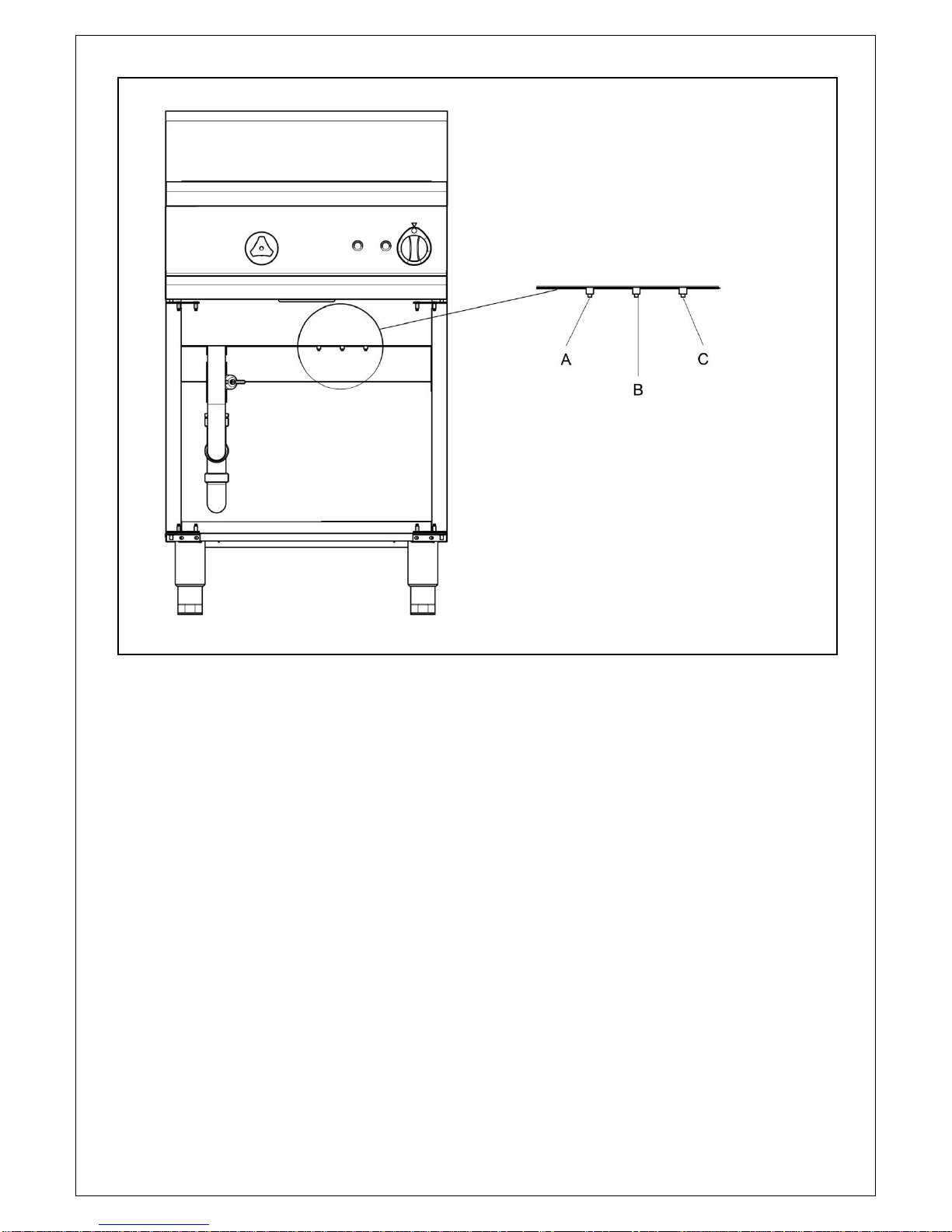
Safety cutout
This appliance is fitted with safety cutout thermostats which will shut the appliance
down in the event of a fault. If the appliance fails to heat when the control knob is set
to a heating position, the safety cut-outs may require resetting. Disconnect the
appliance from the supply, allow to cool for at least 20 minutes and then reset the
exposed buttons indicated in Fig 4. Note that Fig 4 shows OE7702 –the OE7701 has
only 2 cutout buttons.
Once reset, reconnect to supply and operate as normal. If the appliance still fails to
operate, consult one of our recommended Service Engineers.
Shutdown
To turn the appliance off, rotate the control knob to the ‘Off’ position and turn off the
electrical supply at the isolator.

IS 399 ECN 3607 Page 9 of 15
Fig 4
Draining the tank
Isolate the appliance from the supply and allow the water to cool to a maximum of 55
Deg C.
Open the drain tap (Fig 5) and allow the water to drain.
Opening the water control valve will assist in swirling water around the tank to rinse
away any debris.
Close the drain tap to the safe locked position.
Safety thermostat resets
A LH element
B Centre element
C RH element

IS 399 ECN 3607 Page 10 of 15
Fig 5
CLEANING
Do not use a water jet or steam cleaner, and do not immerse this appliance.
Clean all panels with warm water and mild detergent, do not use abrasive materials
or cleaners containing chlorine. Dry with a soft cloth.
Align squares at A
Depress to engage –turn to
open and close

IS 399 ECN 3607 Page 11 of 15
Cleaning the tanks
Food debris can be a health risk –ensure that all debris is removed from the tanks
after use.
Wash the tanks, top surface of the hob, basket drainer, overflow cover, basket
support and pan support with a warm detergent solution.
Rinse out the tank and flush away any traces of detergent.
Close the drain tap, replace the basket drainer, overflow cover, batter plate and pan
support.
Refill the tank with fresh water.
De-scaling
The formation of scale within a hot water system is common, and if left unchecked
may cause problems to the functioning of the appliance. Check regularly for scale
build up - allow the appliance to cool before carrying out inspection for scale.
De-scale regularly using an approved de-scaling compound such as can be
supplied by Lincat (Code MS19). Do not use hydrochloric acid based de-
scaling compounds on stainless steel.
To de-scale the appliance, fill with water to the indicated level.
Turn on the control thermostat and allow the water to boil. Turn the thermostat off.
Add the de-scaling compound a little at a time following the manufacturer’s
instructions. Allow the froth to subside. Turn the appliance on full again.
Heat up for 30 minutes and allow the water to cool. Repeat the process if
necessary.
Isolate the appliance from the supply, drain the tank and rinse with clean water.
SERVICING, MAINTENANCE AND
COMPONENT REPLACEMENT
All servicing, maintenance and component replacement on this appliance should be
carried out by one of our recommended service engineers.
A general check on the installation should include observation of the following:
Is the appliance installed with the correct rating of cable?
Is it connected to the supply via an isolating switch?

IS 399 ECN 3607 Page 12 of 15
Check all components for correct operation and replace if necessary.
Check the operation of the safety thermostats –see Fig 4 for their location.
Component replacement
Energy regulator
Remove the control knob –do not lose the retaining clip.
Remove the screws beneath the facia panel and drop the panel down.
Remove the retaining screws of the regulator. Remove the cables.
Reassemble with new regulator in the reverse order.
Contactor
Remove the rear cover.
Disconnect the cables from the contactor, placing them on the new contactor as
each is removed to ensure correct wiring.
Remove the contactor from the frame and refit the new contactor by reversing the
procedure.
Safety thermostat
Remove the front and rear element covers from inside the appliance.
Remove the thermostat mounting nut from the relevant thermostat.
Slide thermostat phial from element sleeve.
Disconnect cables and fit new safety thermostat by reversing the procedure.
Element
Remove the front and rear element covers from inside the appliance.
Remove the safety thermostat as above.
Remove 6 element mounting nuts to release element mounting flange.
Disconnect cables from element.
Remove element and sealing gasket from inside of tank.
Fit new element and reassemble in reverse order.
Important: When tightening element mounting nuts ensure that they are
tightened to a torque figure of 1N/m. Over-tightening will distort the gasket,
resulting in a non-watertight seal.

IS 399 ECN 3607 Page 13 of 15
FAULT FINDING
Appliance will not heat
Is the green neon illuminated
Yes
No
Check mains
isolator and fuse
Is the energy regulator turned
on
No
Turn on the
energy regulator
Yes
Is the amber neon illuminated
No
Check safety
thermostat resets
Yes
Is the contactor operating
No
Change the
contactor
Yes
Check the element

IS 399 ECN 3607 Page 14 of 15
Part Number
Description
Used on
BA102
Large basket
OE7701
BA109
1/2 basket
OE7702
BA110
1/3 basket
OE7701 (2), OE7702 (3)
BA104
1/6 basket
OE7701 (6), OE7702 (9)
CO166
Swirl inlet fitting
OE7701, OE7702
CO167
½” stop valve
CO168
Compact tee inlet
CO215
Contactor
EL208
Element
EN10
Energy regulator
HA77
Door handle
HA78
Lid handle
HO107
Flexi braid hose
KN233
Control knob
LE37
Leg
NE39
Green neon
NE40
Amber neon
PS05
Pressure switch
SP56
Leg spanner
TA101/A
Drain tap
TE45
Terminal inlet
Part
Number
Description
Used on
OA7926
1/1 150mm deep gastronorm with lid
OE7701, OE7702
OA7927
1/2 150mm deep gastronorm with lid
OA7928
1/3 150mm deep gastronorm with lid
OA7929
1/4 150mm deep gastronorm with lid
OE7702
OA7930
1/6 150mm deep gastronorm with lid
OA7931
1/1 140mm deep perforated gastronorm with lid
OE7701, OE7702
OA7932
1/2 140mm deep perforated gastronorm with lid
SPARE PARTS LIST
ACCESSORIES

IS 399 ECN 3607 Page 15 of 15
For help with the installation, maintenance and use of your Lincat equipment,
please contact our service department:
UK: 01522 875520
For non-UK customers, please contact your local Lincat dealer
All service work, other than routine cleaning should be carried out by one of our
authorised service agents. We cannot accept responsibility for work carried out by
other persons.
To ensure your service enquiry is handled as efficiently as possible, please tell us:
Brief details of the problem
Product code
All available on serial plate
Type number
Serial number
Lincat reserve the right to carry out any work under warranty, given reasonable
access to the appliance, during normal working hours, Monday to Friday, 08:30 to
17:00.
GUARANTEE
This unit carries a comprehensive UK mainland 2 year warranty. The guarantee is
in addition to, and does not diminish your statutory or legal rights.
The guarantee does not cover:
Accidental damage, misuse or use not in accordance with the manufacturer’s
instructions
Consumable items (such as filters, glass, bulbs, slot toaster elements and door
seals.)
Damage due to incorrect installation, modification, unauthorised service work or
damage due to scale, food debris build-up, etc.
The manufacturer disclaims any liability for incidental, or consequential damages.
Attendance is based on reasonable access to the appliance to allow the authorised
technician to carry out the warranty work.
Service calls to equipment under warranty will be carried out in accordance with the
conditions of sale. Unless otherwise specified, a maximum of 15 minutes of
administrative time, not spent directly carrying out servicing work, is provided for
within the warranty. Any requirement for staff attending the call to spend greater time
than 15 minutes due to administrative requirements, such as on health and safety risk
assessments, will be chargeable at the prevailing rate.
SERVICE INFORMATION
Other manuals for Opus 700 Series
7
This manual suits for next models
2
Table of contents
Other Lincat Pasta Maker manuals
Popular Pasta Maker manuals by other brands

Falcon
Falcon DOMINATOR PLUS E3204 Installation and servicing instructions

Takka
Takka X-1000 Recipe & Instruction Book

Bartscher
Bartscher SNACK 650 Series Instructions for installation, operation and maintenance

Zass
Zass ZPM 01 operating instructions

EUROPRO
EUROPRO Bravetti KPS110H owner's manual

Tupperware
Tupperware 10049020724 manual