Lincoln C Series Owner's manual

Page
Section - E35
- 43D
Form 404031
FEB - 2007
MODEL 84673
BARE REEL
SERIES “C”
OWNER/OPERATOR MANUAL
SPECI FICATIONS
Maximum working pressure 2000 p.s.i.
Material Inlet 3/4” NPT (Female)
Material outlet 3/4” NPT (Female)
Sheave width 10”
Sheave diameter 19-1/4”
Drum diameter 12-3/4”
Overall width 15-1/2”
Overall height 22-1/2”
Overall depth 21”
Maximum hose capacities (Including hang down):
5/8” or 3/4” I.D. Hose 75 Ft.
NOTE: Maximum hose capacities are based on SAE speci-
fied hoses. Exceeding these capacities voids warranty. Refer
to DELIVERY HOSE INSTALLATION for proper hose to reel
assembly.
DESCRIPTION
Model 84673 unit is a heavy duty lubreel designed for
bus and truck lubrication or wherever extra heavy duty
construction and longer length delivery hose is required.
The reel can be installed as a single unit or in multiple
configurations.
Reel features include a reel latch that automatically
locks at desired positions as the hose is extended and
releases with a short pull on the hose.
OWNER/OPERATOR RESPONSIBILITY
It is the owner/operator responsibility to properly use
and maintain this equipment.
The instructions and warnings contained in this manual
shall be read and understood by the owner/operator
prior to operating this equipment.
If an owner/operator does not understand English, the
contents of this manual shall be explained in the owner/
operator native language to assure the owner/operator
comprehends.
It is the owner/operator responsibility to maintain the leg-
ibility of all warning and instruction labels.
The owner/operator shall retain this manual for fu-
ture reference to important warnings, operating and
maintenance instructions.
One Lincoln Way
St. Louis, MO 63120-1578
Customer Service +1.314.679.4200
Fax +1.800.424.5359

Page Number - 2 Form 404031
• Do not exceed the stated maximum working pressure of the reel or of the lowest rated component in your system.
• Do not alter or modify any part of this equipment.
• Do not operate this equipment with combustible gas.
• Do not attempt to repair or disassemble the equipment while the system is pressurized.
• Make sure all fluid connections are securely tightened before using this equipment.
• Always read and follow the fluid manufacturers recommendations regarding fluid compatibility, and the use of protective
clothing and equipment.
• Check all equipment regularly and repair or replace worn or damaged parts immediately.
• Never point the dispensing valve at any part of the body or at another person.
• Never try to stop or deflect material from dispensing valve or leading connection or component with your hand or body.
• Always check equipment for proper operation before each use, making sure safety devices are in place and operating prop-
erly.
• Always follow the pressure relief procedure after shutting off the pump, when chocking or servicing any part of the system,
and when installing, cleaning or changing any part of the system.
FAILURE TO HEED THE FOLLOWING WARNINGS INCLUDING MISUSE, OVER PRESSURIZING, MODIFYING PARTS,
USING INCOMPATIBLE CHEMICALS AND FLUIDS, OR USING WORN OR DAMAGED PARTS, MAY RESULT IN
EQUIPMENT DAMAGE AND/OR SERIOUS PERSONAL INJURY, FIRE, EXPLOSION, OR PROPERTY DAMAGE.
ASSEMBLY
Assemble reel as follows. Refer to SERVICE PARTS for part
numbers and location.
A. Assemble arbor and ratchet casting (237769) to support
assembly (237656) with hex head screws (50014) and
secure with hex nuts (51022).
B. Lubricate V-ring seal (237671) and assemble onto arbor
and ratchet casting (237769) with lip facing away from
arbor ratchet.
C. Assemble power spring assembly (248494) onto arbor and
ratchet casting (248494) until spring canister bottoms on
arbors shoulder.
D. Lubricate V-ring seal (237673) and assemble onto arbor
and ratchet casting (237769) with lip facing toward spring
canister.
E. Assemble axle assembly (242000) to sheave assembly
(237771) and secure with standoffs (237780).
F. Assemble axle and sheave assembly to reel by sliding the
axle assembly (242000) through the bearings in the arbor
and ratchet casting (237769) and securing with washer
(48217) and Tru-arc (68424).
Note: Shim as required using shims (48385) between
washer (48217) and arbor and ratchet casting (237769) to
eliminate axle end play.
G. Assemble outboard axle assembly (237781) to standoffs
(237780) and secure with nuts (51412).
H. Rotate sheave assembly (237771) and align mounting
holes with mating holes in power spring canister (248494)
and secure using carriage bolts (237738), carriage bolt
(237739) and nuts (51412). Note: The carriage bolt
(237739) (.875 long) must be assembled in hole adjacent
to pawl pin on power spring assembly.
I. Assemble rollers onto 5/16” diameter pins in the order il-
lustrated on page (6). Hold in place while inserting the four
5/16” washer head bolts through the assembly and secure
with four 5/16” washer head nuts. Assemble roller
outlet arm assembly onto three of the bolts (50014) and
secure using three nuts (51022).
J. Assemble swivel assembly(84679) in axle assembly
(242000) and tighten.
K. Assemble swivel outlet adapter (242015) into the axle
assembly (242000) and secure.
L. Assemble hose clamp (272382) to sheave assembly
(237771) with carriage bolt (237738) and secure with nut
(51010).
M. Assemble pawl (237683) to pawl pin on spring canister
(248494) and secure with washer (48327) and Tru-arc
(66316).

Page Number - 3
Form 404031
N. Assemble pawl spring (237695) to pawl (237683) and car-
riage bolt (237739) and secure with locknut (51304).
0. Install Beraing (242725) into Outboard Bearing Assembly
(237784) and secure with Bearing Retainer (272169).
Attach completed Assembly to the Outboard Support
(237787) using screws (50016). HAND TIGHTEN ONLY AT
THIS POINT.
P. Assemble outside bearing assembly and support to reel as-
sembly by sliding outboard axle through bearing. Align two
.406 mounting holes in both base and support and insert
one roll pin in each hole.
Q. Adjust/align outside bearing assembly for free drum.
INSTALLATION
DELIVERY HOSE
DELIVERY HOSE INSTALLATION (MAXIMUM
SPRING TENSION)
For smoother operation during retraction and to increase hose
life, “detaic” hose by wiping entire hose length with a light lubri-
cating oil before installing on reel.
Assemble outlet adapter to hose and tighten securely. Use
teflon tape on threads to prevent leaks.
To prevent damaging hose connections and/or
components when pulling hose from reel, pull on the hose
itself and not on the control valve or swivel. Do not pull or
jerk on the hose when fully withdrawn from the reel.
See Figure (1). Insert hose end with outlet adapter
through roller outlet and secure to axle head with
U-keeper. Make sure seal is installed correctly in axle
before assembling.
From open side of reel (with outside support removed), loop
entire length of hose onto reel in a clockwise direction. Pull hose
out through roller outlet to wind power spring. When hose is
completely extended, latch reel to prevent it from unwinding.
Continue to add loops of hose and pull out
hose until power spring winds tight.
IMPORTANT
INSTRUCTIONS
Perform the following instructions as stated to
correctly set the power spring for maximum tension.
Allow reel to retract two full revolutions and latch
reel. Carefully unloop remaining hose from reel.

Page Number - 4 Form 404031
To avoid damaging reel components,
always make sure hose clamp is prop-
erly installed.
Position hose clamp so that approxi-
mately 1/2 loop of hose remains on reel
and latching does not occur when hose
is fully extended.
Slide ball stop over free end of hose
and position slightly below roller outlet.
Tighten screws to secure ball stop to
hose.
Power spring is now set to maximum
tension.
ADJUSTING SPRING
TENSION
To prevent premature power spring fail-
ure, spring tension should be adjusted
so that it requires at least two full turns
of the reel sheave before the spring is
wound tight.
Should less spring tension be desired,
pull hose out from roller outlet to provide
slack and latch reel.
Unwind one loop of hose from reel. Pull
excess hose out through roller outlet and
unlatch reel to retract hose.
Check tension and repeat above proce-
dure until desired tension is
obtained.
Reattach/assemble outboard support to
reel. (See Page 3, Steps 0 thru 0).
ATTACHING CONNECTING
HOSES
To prevent damage to connecting hose
when installing hose to reel, sufficient
clearance must be provided from out-
side edge of sheave.
See Figure (2). Reconnect inlet adapter
to swivel body and replace U-keeper.
Connect other end of connecting hose
to material supply line source or con-
nection.
REEL INSTALLATION AND

Page Number - 5
Form 404031
Service, One Lincoln Way, St. Louis, MO 63120-1578, (314)
679-4200 for your nearest authorized service center.
When ordering replacement parts, list: part number, descrip-
tion, model number and series number.
LIMITED WARRANTY
Lincoln warrants that lubrication equipment, materials dispens-
ing equipment and other related equipment manufactured by
it will be free from defects in material and workmanship during
the one (1) year following the date of purchase. If equipment
proves to be defective during this warranty period, it will be
repaired or replaced without charge, provided that factory
examination indicates the equipment to be defective. To
obtain repair or replacement, it must be shipped, transpor-
tation charges prepaid, with proof of date of purchase to
a Lincoln authorized Warranty and Service Center, within
the one (1) year following the date of purchase.
This warranty is extended to the original retail purchaser only.
This warranty does not apply to equipment damaged from ac-
cident, overload, abuse, misuse, negligence, faulty installation
or abrasive or corrosive materials, or to equipment repaired
or altered by anyone not authorized by Lincoln to repair or
alter the equipment. This warranty applies only to equipment
installed and operated according to the recommendations of
Lincoln or its authorized field personnel.
No other express warranty applies to lubrication equipment,
materials dispensing equipment, and other related
equipment manufactured by Lincoln. ANY IMPLIED WARRAN-
TIES applicable to lubrication equipment, materials
dispensing equipment, and other related equipment manufac-
tured by Lincoln INCLUDING THE WARRANTIES OF
MERCHANTABILITY AND FITNESS FOR A PARTICULAR
PURPOSE, WILL LAST ONLY FOR ONE (1) YEAR FROM
THE DATE OF PURCHASE. SOME STATES DO NOT ALLOW
LIMITATIONS ON HOW LONG AN IMPLIED WARRANTY
LASTS, SO THE ABOVE LIMITATION MAY NOT APPLY TO
YOU.
In no event shall Lincoln be liable for incidental or consequen-
tial damages. The liability of Lincoln on any claim for loss or
damage arising out of the sale, resale, or use of lubrication
equipment, materials dispensing equipment, and other related
equipment shall in no event exceed the purchase price. SOME
STATES DO NOT ALLOW THE EXCLUSION OR LIMITATION
OF INCIDENTAL OR CONSEQUENTIAL DAMAGES, SO THE
ABOVE LIMITATION OR EXCLUSION MAY NOT APPLYTO
YOU.
THIS WARRANTY GIVES YOU SPECIFIC LEGAL RIGHTS
AND YOU MAY ALSO HAVE OTHER RIGHTS WHICH VARY
FROM STATE TO STATE.
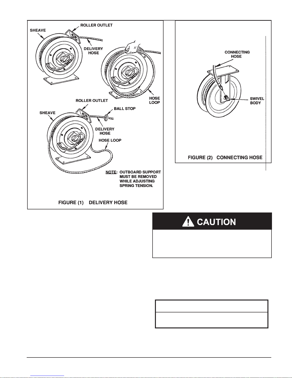
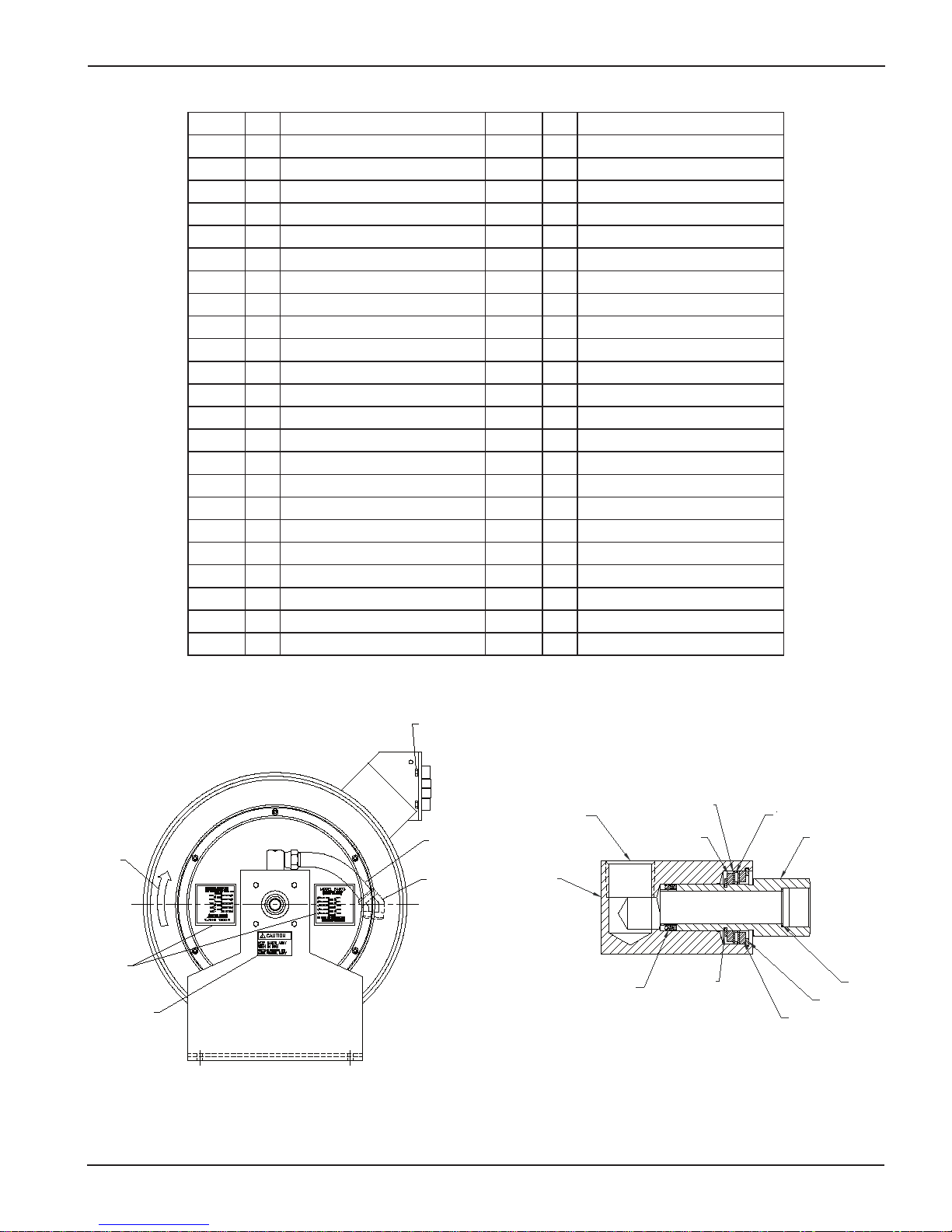
ADJUSTMENT
See Figure (3). The guide arm may be positioned in 22-1/2
degree increments. For ease of operation and increased hose
life, the guide arm should be positioned to minimize hose
strain as the delivery hose is pulled through the roller outlet.
Three studs must be used to securely attach the guide arm, It
may be necessary to change the position of the hex head screw
and one stud in order to obtain the desired guide arm position.
The hose clamp must be relocated if the guide arm is reposi-
tioned.
SAFETY INFORMATION
Read and understand all warnings, cautions and instructions
before operating this equipment. Extreme caution should be
used when operating this equipment as personal injury and/or
property damage can result from equipment misuse. Adequate
personal protection is recommended to prevent splashing of
material on the skin or in the eyes. ALWAYS disconnect air
coupler from pump when the pump is not being used.
PRESSURE RELIEF PROCEDURE
Always perform this procedure when the pump is shut off
and before checking, servicing, installing, cleaning or repairing
any part of this system.
Perform the following procedure:
A. Disconnect the air supply to the pump.
B. Point the dispensing valve away from yourself and others.
C. Open the dispensing valve into an appropriate container
until the pressure is relieved.
If the above procedure does not relieve the pressure, the
dispensing valve or hose may be restricted
To relieve the pressure, very slowly loosen the hose end cou-
pling. Then loosen completely and clear the dispensing valve
and/or hose.
INSPECTION
Prior to operation or maintenance a visual inspection shall be
made. Check reelsystem for leaks, worn or missing parts.
Any reel that appears to be damaged in any way, is badly
worn or operates abnormally shall be removed from use until
repairs are made. Contact factory authorized service center for
repairs.
If overpressurizing of the equipment is believed to have oc-
curred, contact a factory authorized service center for inspec-
tion of the reel.
Annual inspection by a factory authorized service center is
recommended.
DISASSEMBLY
To disassemble, perform ASSEMBLY procedures in reverse.
REPAIR
Repair is limited to replacement of listed service parts. Special
procedures and tools are required. Contact LincolnCustomer

Page Number - 6 Form 404031
565223 565253
272162
237738
(5 Req’d)
242022
(8X) ø .046 Mounting Hole
10.000
272161
(2 Req’d) 272163
(4 Req‘d)
237673
3/4 NPTF Outlet
242015
242000
50016 (4 Req’d)
237784
272169
242725
242738
237781
51412 (3 Req’d)
(Torque to
7-8 Ft. Lbs.) 237780
(3 Req’d)
51412
(Torque to
7-8 Ft. Lbs.)
237738
©272382
237787
272160
(2 Req’d)
272040
(22 Req’d)
248494
237671
48385 (4 Req’d)
(Shim as Req’d)
48217
3/4 NPTF Inlet
84679
68424
50014 (4 Req’d)
51022 (7 Req’d)
237769
13162
237683
66316
48327
237695
51304
237739
51010 (6 Req’d)
237656
237771

Page Number - 7
Form 404031
68340
565256
565262
SERVICE PARTS (CONT)
PART QTY DESCRIPTION PART QTY DESCRIPTION
13162 1 Pin .405 x 1-1/8 237780 3 Standoff
48217 1 Gland Pkg Washer 237781 1 Axle, Outboard Weld
48327 1 Washer, Pkg. .915 OD 237784 1 Outboard Bearing Assembly
48385 4 Washer, Shim 1-3/8 237787 1 Support, Outboard
50014 4 SCR HHCS 5/16-18 x 1-3/4 242000 1 Axle, High Flow
50016 4 Screws 242015 1 Adapter, Swivel
50757 4 SCR HHCS 1/4-20 x 5/8 242022 1 Label, Nameplate
51022 7 Jam Nut 242505 1 Nipple, Formed
51304 1 Lock Nut 242506 1 Elbow, 3/4 FPT x 45
51412 10 Nut, Hex 1/4-20 GR5 242725 1 Bearing, Special
66316 1 Ring, Retaining 242738 1 Cap, Vinyl 1.5 ID BL
68340 1 Decal, Instr 248494 1 Spring, Power Assembly
68424 1 Ring, Retaining EXT TRU 272040 22 Roller
84679 1 Swivel Assembly 272160 2 Pin
237656 1 Support Weld't 272161 2 Pin
237671 1 Pkg, V-Ring 2.68 OD 272162 1 Arm Roller Support Assy
237673 1 Pkg, V-Ring 1.82 OD 272163 4 Retainer, Shaft
237683 1 Pawl, Latch 272169 1 Retaining Ring
237695 1 Spring, Extension 272382 1 Clamp, Hose (for 3/4" ID Hose)
237738 6 Bolt, Carriage 1/4-20 x 1/2 GR5 565223 1 Label, Logo Lincoln
237739 1 Bolt, Carriage 1/4-20 x 1 GR5 565253 1 Label, Caution
237769 1 Arbor and ratchet casting 565256 2 Label, Capacity
237771 1 Sheave 565262 1 Label, Caution
50757
(4 Req’d)
242505
242506
3/4 NPTF (REF)
16684
70518
70517
(2 Req’d)
48652
70519
16685
70515
(2 Req’d)
48653
70516
31116
© Indicates Change
84679 Swivel Assembly
Assemble to Axle with Loctite 242.
Torque to 50 Ft. Lbs.
©

Page Number - 8 Form 404031
Americas:
One Lincoln Way
St. Louis, MO 63120-1578
USA
Phone +1.314.679.4200
Fax +1.800.424.5359
Europe/Africa:
Heinrich-Hertz-Str 2-8
D-69183 Walldorf
Germany
Phone +49.6227.33.0
Fax +49.6227.33.259
© Copyright 2007
Printed in USA
Web site:
www.lincolnindustrial.com
Asia/Pacific:
51 Changi Business Park
Central 2
#09-06 The Signature
Singapore 486066
Phone +65.6588.0188
Fax +65.6588.3438
Lincoln Industrial Standard Warranty
LIMITED WARRANTY
Lincoln warrants the equipment manufactured and supplied by Lincoln to be free from defects in material and workmanship for a
period of one (1) year following the date of purchase, excluding therefrom any special, extended, or limited warranty published by
Lincoln. If equipment is determined to be defective during this warranty period, it will be repaired or replaced, within Lincoln’s sole
discretion, without charge.
This warranty is conditioned upon the determination of a Lincoln authorized representative that the equipment is defective. To
obtain repair or replacement, you must ship the equipment, transportation charges prepaid, with proof of purchase to a Lincoln
Authorized Warranty and Service Center within the warranty period.
This warranty is extended to the original retail purchaser only. This warranty does not apply to equipment damaged from accident,
overload, abuse, misuse, negligence, faulty installation or abrasive or corrosive material, equipment that has been altered, or equip-
ment repaired by anyone not authorized by Lincoln. This warranty applies only to equipment installed, operated and maintained in
strict accordance with the written specifications and recommendations provided by Lincoln or its authorized field personnel.
THIS WARRANTY IS EXCLUSIVE AND IS IN LIEU OF ANY OTHER WARRANTIES, EXPRESS OR IMPLIED, INCLUDING, BUT
NOT LIMITED TO, THE WARRANTY OF MERCHANTIBILITY OR WARRANTY OF FITNESS FOR A PARTICULAR PURPOSE.
In no event shall Lincoln be liable for incidental or consequential damages. Lincoln’s liability for any claim for loss or damages
arising out of the sale, resale or use of any Lincoln equipment shall in no event exceed the purchase price. Some jurisdictions do
not allow the exclusion or limitation of incidental or consequential damages, therefore the above limitation or exclusion may not
apply to you.
This warranty gives you specific legal rights. You may also have other rights that vary by jurisdiction.
Customers not located in the Western Hemisphere or East Asia: Please contact Lincoln GmbH & Co. KG, Walldorf, Germany, for
your warranty rights.
Lincoln Industrial Special Limited Warranties
SPECIAL LIMITED 2 YEAR WARRANTY
SL-V Series, Single Injectors-85772, 85782, and Replacement Injectors-85771, 85781
Lincoln warrants the SL-V Injector series to be free from defects in material and workmanship for two (2) years following the date
of purchase. If an injector model (single or replacement) is determined to be defective by Lincoln, in its sole discretion, during this
warranty period, it will be repaired or replaced, at Lincoln’s discretion, without charge.
SPECIAL LIMITED 5 YEAR WARRANTY
Series 20, 25, 40 Bare Pumps, Heavy Duty and 94000 Series Bare Reels
Lincoln warrants series 20, 25, 40 bare pumps, and Heavy Duty and 87000 series (94100, 94300, 94500) bare reels to be free from
defects in material and workmanship for five (5) years following the date of purchase. If equipment is determined by Lincoln, in
its sole discretion, to be defective during the first year of the warranty period, it will be repaired or replaced at Lincoln’s discretion,
without charge. In years two (2) and three (3), the warranty on this equipment is limited to repair with Lincoln paying parts and labor
only. In years four (4) and five (5), the warranty on this equipment is limited to repair with Lincoln paying for parts only.
Lincoln Industrial Contact Information
To find Lincoln Industrial’s Nearest Service Center call one of the following numbers, you may also use our website
Customer Service 314-679-4200
Website lincolnindustrial.com
Other manuals for C Series
6
This manual suits for next models
2
Table of contents
Other Lincoln Cables And Connectors manuals
Popular Cables And Connectors manuals by other brands

PCB Piezotronics
PCB Piezotronics IMI SENSORS 009M205/100 Installation and operating manual

Roline
Roline 14.01.3556 user manual

Hioki
Hioki 9636 instruction manual

Balluff
Balluff BKS-S32M-00 Assembling Instruction

PCB Piezotronics
PCB Piezotronics 034F50 Installation and operating manual

LEAB
LEAB LPS II quick start guide