Lincoln E Series User manual

Page
Section - E35 - 40N
Form 403733
MAR - 2008
MODEL 84275
BARE REEL
SERIES “E”
SPECIFICATIONS
Maximum working pressure 5000 p.s.i.
Material Inlet 1/2” NPT (Female)
Material outlet 1/2” NPT (Female)
Sheave width 10”
Sheave diameter 19-1/4”
Drum diameter 12-3/4”
Overall width 13-1/2”
Overall height 22-1/2”
Overall depth 21”
Maximum hose capacities (Including hang down):
3/8” I.D. Grease hose (SAE 100 R2) 75 ft.
1/2” I.D. Grease hose (SAE 100 R2) 75 ft.
1/2” I.D. Oil hose (SAE 100 R3) 75 ft.
5/8” I.D. Grease hose (SAE 100 R1) 75 ft.
NOTE: Maximum hose capacities are based on SAE
specied hoses. Exceeding these capacities voids war-
ranty.
Refer to DELIVERY HOSE INSTALLATION for proper hose
to reel assembly.
DESCRIPTION
Model 84275 Hose Reel is a spring operated unit designed
to hold and retract up to 75 ft. of 5/8” diameter hose, see
hole capacities chart.
The reel is a heavy duty unitl designed for bus and truck
lubrication or wherever extra heavy duty
construction and longer length delivery hose is required
. The reel can be installed as a single unit or in multiple
congurations.
Reel features include a reel latch that automatically locks
at desired positions as the hose is extended and releases
with a short pull on the hose.
OWNER/OPERATOR
RESPONSIBILITY
It is the owner/operator responsibility to properly use and
maintain this equipment.
The instructions and warnings contained in this manual
shall be read and understood by the owner/operator prior
to operating this equipment.
If an owner/operator does not understand English, the
contents of this manual shall be explained in the owner/
operator native language to assure the owner/operator
comprehends.
It is the owner/operator responsibility to maintain the leg-
ibility of all warning and instruction labels.
The owner/operator shall retain this manual for future ref-
erence to important warnings, operating and maintenance
instructions.

Page Number - 2 Form 403733
Failure to heed the following warnings including mis-
use, over pressurizing, modifying parts, using incom-
patible chemicals and uids, or using worn or damages
parts, may result in equipment damage and/or serious
personal injruy, re explosions, or property damage.
• Do not exceed the stated maximum working pressure
of the reel or of the lowest rated component in your
system.
• Do not alter or modify any part of this equipment.
• Do not operate this equipment with combustible gas.
• Do not attempt to repair or disassemble the equipment
while the system is pressurized.
• Make sure all uid connections are securely tightened
before using this equipment.
• Always read and follow the uid manufacturer’s
recommendations regarding uid compatibility, and
the use of protective clothing and equipment.
• Check all equipment regularly and repair or replace
worn or damaged parts immediately.
• Never point the dispensing valve at any part of the body
or at another person.
• Never try to stop or deect material from dispensing
valve or leading connection or component with your
hand or body.
• Always check equipment for proper operation before
each use, making sure safety devices are in place and
operating properly.
• Always follow the pressure relief procedure after shutting
off the pump, when checking or servicing any part of the
system, and when installing, cleaning or changing any
part of the system.
ASSEMBLY
Assemble reel as follows. Refer to SERVICE PARTS for part
numbers and location.
A. Assemble arbor and ratchet casting (237769) to support
assembly (237656) with hex head screws (50014) and
secure with hex nuts (51022).
B. Lubricate V-ring seal (237671) and assemble onto arbor
and ratchet casting (237769) with lip facing away from
arbor ratchet.
C. Assemble power spring assembly (248494) onto arbor
and ratchet casting (237769) until spring canister bottoms
on arbors shoulder.
D. Lubricate V-ring seal (237673) and assemble onto arbor
and ratchet casting (237769) with lip facing toward spring
canister.
E. Assemble axle assembly (274845) to sheave assembly
(237771) and secure with standoffs (237780).
F. Assemble axle and sheave assembly to reel by sliding the
axle assembly (274845©) through the bearings in the arbor
and ratchet casting (237769) and securing with washer
(48217) and Tru-arc (68424).
NOTE: Shim as required using shims (48385) between
washer (48217) and arbor and ratchet casting (237769) to
eliminate axle end play.
G. Assemble outboard axle assembly (237781) to standoffs
(237780) and secure with nuts (51412).
H. Rotate sheave assembly (237771) and align mounting
holes with mating holes in power spring canister
(237768) and secure using carriage bolts (237738),
carriage bolt (237739) and nuts (51412).
NOTE: The carriage bolt (237739) (.875 long) must be
assembled in hole adjacent to pawl pin on power spring
assembly.
I. Assemble rollers onto 5/16” diameter pins in the order
illustrated on page (6). Hold in place while inserting the
four 5/16” washer head bolts through the asembly and
secure with four 5/16” washer head nuts. Assemble
roller outlet arm assembly onto three of the bolts
(50014) and secure using three nuts (51002).
J. Assemble swivel assembly (274840) in axle assembly
(274845) and tighten.
K. Assemble inlet adapter (273065) into the swivel assembly
(274840) and secure with U-keeper (15674).
L. Assemble outlet adapter (273212) into the axle assembly
(274845) and secure with U-keeper (15674).
NOTE: Lubricate seal before assembling.
M. Assemble hose clamp (272382) to sheave assembly
(237771) with carriage bolt (237738) and secure with nut
(51010).
NOTE: Lubricate seal before assembling.
N. Assemble pawl (237683) to pawl pin on spring canister
(237768) and secure with washer (48327) and Tru-arc
(66316).
O. Assemble pawl spring (237695) to pawl (237683) and
carriage bolt (237739) and secure with locknut (51304).
P. Install Bearing (242725) into Outboard Bearing Assembly
(237784) and secure with Bearing Retainer (69281). Attach
completed Assembly to the Outboard Support (237787) using
screws (50016). HAND TIGHTEN ONLY AT THIS POINT.
Q. Assemble outside bearing assembly and support to reel
assembly by sliding outboard axle through bearing. Align
two .406 mounting holes in both base and support and
insert one roll pin in each hole.
R. Adjust/align outside bearing assembly for free drum rotation
and tighten screws (50016).

Page Number - 3
Form 403733
To prevent damaging hose connections and/or
components when pulling hose from reel, pull on the hose
itself and not on the control valve or swivel. Do not pull or
jerk on the hose when fully withdrawn from the reel.
INSTALLATION
DELIVERY HOSE INSTALLATION
(MAXIMUM SPRING TENSION)
For smoother operation during retraction and to increase hose
life, “de-tack” hose by wiping entire hose length with a light
lubricating oil before installing on reel.
Assemble outlet adapter to hose and tighten securely. Use
teon tape on threads to prevent leaks.
See Figure (1). Insert hose end with outlet adapter through
roller outlet and secure to axle head with U-keeper. Make sure
seal is installed correctly in axle before assembling.
From open side of reel (with outside support removed), loop en-
tire length of hose onto reel in a clockwise direction. Pull hose
out through roller outlet to wind power spring. When hose is
completely extended, latch reel to prevent it from unwinding.
Continue to add loops of hose and pull out hose until power
spring winds tight.
Allow reel to retract two full revolutions and latch reel.
Carefully unloop remaining hose from reel.
Position hose clamp so that approximately 1/2 loop of hose
remains on reel and latching does not occur when hose is fully
extended.
IMPORTANT
INSTRUCTIONS
Perform the following instructions as stated to correctly set
the power spring for maximum tension.
To avoid damaging reel components, always make sure
hose clamp is properly installed.

Page Number - 4 Form 403733
To prevent premature power spring failure, spring tension
should be adjusted so that it requires at least two full turns
of the reel sheave before the spring is wound tight.
Should less spring tension be desired, pull hose out from roller
outlet to provide slack and latch reel.
Unwind one loop of hose from reel. Pull excess hose out
through roller outlet and unlatch reel to retract hose.
Check tension and repeat above procedure until desired ten-
sion is obtained.
Reattach/assemble outboard support to reel. (See Page 2,
Steps Q thru S).
ATTACHING CONNECTING HOSES
To prevent damage to connecting hose when installing hose
to reel, sufcient clearance must be provided from outside
edge of sheave.
Slide ball stop over free end of hose and position slightly below
roller outlet. Tighten screws to secure ball stop to hose.
Power spring is now set to maximum tension.
ADJUSTING SPRING TENSION
See Figure (2). Remove U-keeper and inlet adapter from swivel
body.
If U-Cup at Adapter Assembly (273065) is damaged, replace the
whol Adapter Assembly (273065).
Assemble swivel adapter to connecting hose.
Reconnect inlet adapter to swivel body and replace U-keeper.
Connect other end of connecting hose to material supply line
source or connection.
REEL INSTALLATION AND
ADJUSTMENT
See Figure (3). The guide arm may be positioned in 22-1/2
degree increments. For ease of operation and increased
hose life, the guide arm should be positioned to minimize hose
strain as the delivery hose is pulled through the roller outlet.
Three studs must be used to securely attach the guide arm.
It may be necessary to change the position of the hex head
screw and one stud in order to obtain the desired guide arm
position.
The hose clamp must be relocated if the guide arm is reposi-
tioned.

Page Number - 5
Form 403733
SAFETY INFORMATION
Read and understand all warnings, cautions and instructions
before operating this equipment. Extreme caution should be
used when operating this equipment as personal injury and/or
property damage can result from equipment misuse. Ade-
quate personal protection is recommended to prevent splash-
ing of material on the skin or in the eyes. ALWAYS disconnect
air coupler from pump when the pump is not being used.
PRESSURE RELIEF PROCEDURE
Always perform this procedure when the pump is shut off and
before checking, servicing, installing, cleaning or repairing any
part of this system.
Perform the following procedure:
A. Disconnect the air supply to the pump.
B. Point the dispensing valve away from yourself and others.
C. Open the dispensing valve into an appropriate container
until the pressure is relieved.
If the above procedure does not relieve the pressure, the dis-
pensing valve or hose may be restricted. To relieve the pres-
sure, very slowly loosen the hose end coupling. Then loosen
completely and clear the dispensing valve and/or hose.
Lincoln Industrial Standard Warranty
LIMITED WARRANTY
Lincoln warrants the equipment manufactured and supplied by Lincoln to be free from defects in material and workmanship for a period of one (1) year following the
date of purchase, excluding there from any special, extended, or limited warranty published by Lincoln. If equipment is determined to be defective during this warranty
period, it will be repaired or replaced, within Lincoln’s sole discretion, without charge.
This warranty is conditioned upon the determination of a Lincoln authorized representative that the equipment is defective. To obtain repair or replacement, you must
ship the equipment, transportation charges prepaid, with proof of purchase to a Lincoln Authorized Warranty and Service Center within the warranty period.
This warranty is extended to the original retail purchaser only. This warranty does not apply to equipment damaged from accident, overload, abuse, misuse, negligence,
faulty installation or abrasive or corrosive material, equipment that has been altered, or equipment repaired by anyone not authorized by Lincoln. This warranty applies
only to equipment installed, operated and maintained in strict accordance with the written specications and recommendations provided by Lincoln or its authorized
eld personnel.
THIS WARRANTY IS EXCLUSIVE AND IS IN LIEU OF ANY OTHER WARRANTIES, EXPRESS OR IMPLIED, INCLUDING, BUT NOT LIMITED TO, THE WARRANTY
OF MERCHANTIBILITY OR WARRANTY OF FITNESS FOR A PARTICULAR PURPOSE.
In no event shall Lincoln be liable for incidental or consequential damages. Lincoln’s liability for any claim for loss or damages arising out of the sale, resale or use of
any Lincoln equipment shall in no event exceed the purchase price. Some jurisdictions do not allow the exclusion or limitation of incidental or consequential damages,
therefore the above limitation or exclusion may not apply to you.
This warranty gives you specic legal rights. You may also have other rights that vary by jurisdiction.
Customers not located in the Western Hemisphere or East Asia: Please contact Lincoln GmbH & Co. KG, Walldorf, Germany, for your warranty rights.
Lincoln Industrial Special Limited Warranties
SPECIAL LIMITED 2 YEAR WARRANTY
SL-V Series, Single Injectors-85772, 85782, and Replacement Injectors-85771, 85781
Lincoln warrants the SL-V Injector series to be free from defects in material and workmanship for two (2) years following the date of purchase. If an injector model
(single or replacement) is determined to be defective by Lincoln, in its sole discretion, during this warranty period, it will be repaired or replaced, at Lincoln’s discretion,
without charge.
SPECIAL LIMITED 5 YEAR WARRANTY
Series 20, 25, 40 Bare Pumps, Heavy Duty and 94000 Series Bare Reels
Lincoln warrants series 20, 25, 40 bare pumps, and Heavy Duty and 87000 series (94100, 94300, 94500) bare reels to be free from defects in material and workmanship
for ve (5) years following the date of purchase. If equipment is determined by Lincoln, in its sole discretion, to be defective during the rst year of the warranty period, it
will be repaired or replaced at Lincoln’s discretion, without charge. In years two (2) and three (3), the warranty on this equipment is limited to repair with Lincoln paying
parts and labor only. In years four (4) and ve (5), the warranty on this equipment is limited to repair with Lincoln paying for parts only.
INSPECTION
Prior to operation or maintenance a visual inspection shall be
made. Check reel system for leaks, worn or missing parts.
Any reel that appears to be damaged in any way, is badly
worn or operates abnormally shall be removed from use until
repairs are made. Contact factory authorized service center
for repairs.
If overpressurizing of the equipment is believed to have oc-
curred, contact a factory authorized service center for inspec-
tion of the reel.
Annual inspection by a factory authorized service center is
recommended.
DISASSEMBLY
To disassemble, perform ASSEMBLY procedures in reverse.
REPAIR
Repair is limited to replacement of listed service parts. Special
procedures and tools are required. Contact Lincoln Customer
Service, One Lincoln Way, St. Louis, MO 63120-1578, (314)
679-4200 for your nearest authorized service center.
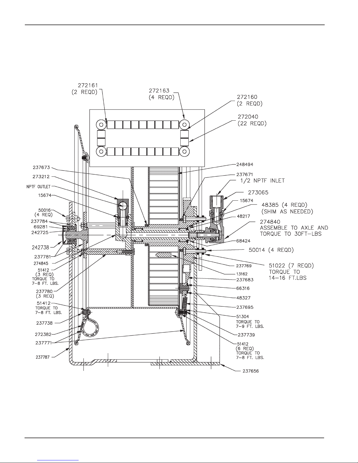
When ordering replacement parts, list: part number,
description, model number and series letter.

Page Number - 6 Form 403733
SERVICE PARTS
© Indicates change
* Included in 275536 Kit.
©
*
*
*
*

Page Number - 7
Form 403733
IMPORTANT
ACCESSORY PART NUMBERS 242503 NIPPLE AND 242504 ELBOW ARE REQUIRED FOR
PROPER DELIVERY HOSE INSTALLATION ON LARGE I.D. HOSES (5/8” I.D. AND LARGER).
THESE PARTS ARE NOT PART OF REEL AND ARE SOLD SEPARATELY.
DETAIL A
VIEW B (ROTATED)
*
* Included in 275536 Kit.
*
*

Page Number - 8 Form 403733
SERVICE PARTS (CONT)
PART OTY DESCRIPTION PART QTY DESCRIPTION
11840 1 Packing retainer 237739 1 Carriage bolt
11841 1 Swivel stud 237769 1 Arbor & ratchet casting
13162 1 Spring pin 237771 1 Sheave assembly
15674 2 U-keeper 237777 1 Name plate
16392 1 Swivel nut 237780 3 Stand off
31035 1 Gasket 237781 1 Outboard Axle assembly
35095 1 Swivel packing 237784 1 Outboard bearing assembly
48217 1 Washer 237787 1 Outboard support
48263 1 Packing washer 242725 1 Bearing cap
48264 2 Thrust washer 242738 1 Vinyle cap
48327 1 Washer 248494 1 Power spring assembly
48385 4 Shim washer 272040 22 Roller
50014 4 Hex head screw 272160 2 Pin .227 X 1.97
50016 4 Hex head screw 272161 2 Pin .227 X 7.23
51022 7 Hex nut 272162 1 Roller support arm ass’y.
51304 1 Locknut 272163 4 Pin retainer
51412 10 Hex nut 272382 1 Hose clamp
66250 13 Ball 272742 1 Swivel body
66316 1 Tru-arc *273065 1 Inlet Adapter Assembly
68424 1 Tru-arc *273212 1 Outlet Adapter Assembly
69281© 1 Retaining ring 565222 1 Logo label
237656 1 Support assembly 565253 1 Caution label
237671 1 V-ring seal 565254 2 Hose capacity label
237673 1 V-ring seal *274836 1 Swivel adapter
237683 1 Latch pawl *274837 1 O-Ring
237695 1 Extension spring *274840 1 Swivel assembly
237738 6 Carriage bolt *274845 1 Axle
*274837 1O-ring
Americas:
One Lincoln Way
St. Louis, MO 63120-1578
USA
Phone +1.314.679.4200
Fax +1.800.424.5359
Asia/Pacic:
51 Changi Business Park
Central 2
#09-06 The Signature
Singapore 486066
Phone +65.6588.0188
Fax +65.6588.3438
© Indicates change
* Included in 275536 Kit.
NOTE: This kit will update any 84275 Reel that is Series “C” or later.
© Copyright Lincoln Industrial
Corp. 2008
Printed in USA
Web site:
www.lincolnindustrial.com
Europe /Africa/Middle East
Lincoln GmbH
Heinrich-Hertz-Str. 2-8
69190 Walldorf - Germany
Phone/Fax +49.6227.33-0/-259
www.lincolnindustrial.de
This manual suits for next models
1
Table of contents
Other Lincoln Cables And Connectors manuals
Popular Cables And Connectors manuals by other brands

National Instruments
National Instruments SCXI-1345 installation guide

Steren
Steren COM-437 instruction manual

ADC
ADC Triaxial Camera Connectors ProAx Specification sheet

PXM
PXM PX349 user manual

ELEKTRA
ELEKTRA SelfTec16 ready2heat instruction manual

PCB Piezotronics
PCB Piezotronics 018C30 Installation and operating manual