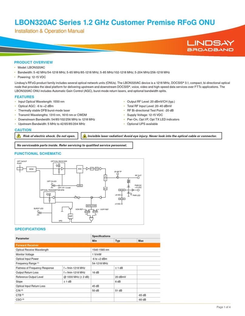
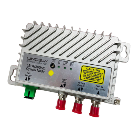
Lindsay Broadband LBON820ACT Series User manual

LBON820ACT Series 1.2 GHz 8-Port OBI-Free RFoG ONU (Fiber to the Tap - FTTT)
INSTALLATION MANUAL
Page 1 of 4
Lindsay’s LBON820ACT RFoG node is a new member to the family of bi-directional RFoG optical nodes using WDM transmission, the ideal platform for delivering
upstream and downstream DOCSIS®voice, video, and high-speed data services. The LBON820ACT ONU is an outdoor-hardened, 8-port optical node (strand,
pedestal, or wall-mounted) designed for Fiber to the Tap (FTTT). Operators can use this device in place of a coax cable TV multitap to extend fiber to each tap location
in brownfield applications.
It is capable of in-field, upgradeable bandsplits (42/54 MHz, 85/102 MHz, and 204/258 MHz). Downstream wavelength is 1550 nm and OBI-free upstream is 1610 nm
(eight selectable wavelengths separated by 0.25 nm).
The LBON820ACT ONU has electronically adjustable controls for forward attenuator, forward equalizer and reverse attenuator. It is powered via HFC power (40-90
VAC) or 100-240 VAC mains power.
FEATURES
•1.2 GHz bandwidth
•In-field Upgradeable Bandsplits: 42/54, 85/102 or 204/258 MHz
•Optical Input Wavelength: 1550 ± 10 nm
•Optical AGC: -6 to +2 dBm
•Electronically adjustable attenuation & slope
•RF Output: 25 dBmV from tap ports
•Auxiliary port for connecting up to eight more subscribers
•-20 dB RF test points
•Selectable CW or burst-mode laser
•Eight selectable wavelengths separated by 0.25 nm
•Aluminum diecast housing
•Strand, wall or pedestal-mounted
•Low power consumption
•Operating Temperature: -40°C to +60°C (-40°F to +140°F)
PRODUCT OVERVIEW
•Model: LBON820ACT
•Bandwidth: 5-42 MHz/54-1220 MHz; 5-85 MHz/102-1220 MHz; 5-204 MHz/258-1220 MHz
•Powering: 40-90 VAC HFC; 100-240 VAC mains
CAUTION
Risk of electric shock. Do not open.
No serviceable parts inside. Refer servicing to qualified service personnel.
Remember to close the lid after adjusting. Lid must be in place for safety and protection.
FUNCTIONAL SCHEMATIC

LBON820ACT Series 1.2 GHz 8-Port OBI-Free RFoG ONU (Fiber to the Tap - FTTT) INSTALLATION MANUAL
Page 2 of 4
SPECIFICATIONS
Parameter Specification
Min Typ Max
Forward Receiver
Optical Receive Wavelength 1540-1560 nm
Optical Input Power Optical AGC -6 to +2 dBm
Optical Return Loss 45 dB Min
RF Frequency Range
(1)
fmin 1218 MHz
Flatness of Frequency Response f = fmin-1218 MHz ± 1 dB
Output Return Loss f = fmin-1218 MHz 16 dB
Output Level per Tap Port
(2)
@ 1218 MHz (± 2 dB) 25 dBmV
Output Level from Auxillary Port
(2)
@ 1218 MHz (± 2 dB) 38 dBmV
Adjustable Slope (RF frequency range) ± 1 dB 20 dB
Port-to-Port Isolation 25 dB
Forward RF Output Test Point with
Respect to Auxillary Port ± 1.5 dB -20 dB
C/N
(2)
50 dB 51 dB
CTB
(2)
-65 dB
CSO
(2)
-60 dB
Return Transmitter
Optical Wavelength
(3)
1610 ± 6.5 nm
Optical Wavelength Separation
(3)
0.25 nm
Optical Wavelength Drift over Temperature ≤ 0.5 nm
Optical Output Power 2 mW
RF Input Level into the Tap Port Total power 20-40 dBmV
Dynamic Input Range
(4)
15 dB
RF Frequency Range
(1)
5 MHz fmax
Flatness of Frequency Response f = 5 MHz to fmax ± 0.75 dB ± 1 dB
Input Return Loss f = 5 MHz to fmax 16 dB
Optical Return Loss 45 dB Min
TX OMI
(5)
35%
Laser Turn ON Level from subscriber port (± 1.5 dB) 26 dBmV
Laser Turn OFF Level from subscriber port (± 1.5 dB) 7 dBmV
Laser Turn ON Time 1.3 µs
Laser Turn OFF Time 1.6 µs
Power, Environmental & Physical
Total Power Consumption ≤ 20 W
Powering 40-90 VAC HFC or 100-240 VAC mains powering
Operating Temperature -40°C to +60°C (-40°F to +140°F)
Humidity 95%, non-condensing
Dimensions (H x W x D) 7.5”H x 9.0”W x 4.1”D (19.0xH x 23.0W x 10.5D cm)
Weight 5.1 lb (2.3 kg)
NOTES:
(1) Diplex splits available: fmin = 42, 85 or 204 MHz; fmax = 54, 102 MHz or 258 MHz. Field-upgradeable diplex filter
(2) RF output levels refer to analog levels, for digital assume -6 dB. Link parameters: -1 dBm optical input, 3.5% OMI/
channel, 54-550 MHz analog channels & digital channels above 550 MHz
(3) Eight user-selectable optical wavelengths separated by 0.25 nm to choose from 1603.5-1616.5 nm
(4) NPR @ 30 dB. Measured using a receiver with an equivalent input noise (EIN) of < 2.5 pA/Hz0.5 with a link budget of
23 dB (20 km fiber + passive loss)
(5) SCTE 174 2018 with a 39 dBmV single tone input from subscriber port. 35% ± 3 dB OMI

LBON820ACT Series 1.2 GHz 8-Port OBI-Free RFoG ONU (Fiber to the Tap - FTTT) INSTALLATION MANUAL
Page 3 of 4
OPTICAL, RF & POWER CONNECTIONS
1. The powering port and all RF ports are standard F-type coaxial connectors.
2. Power input to the ONU is either 40-90 VAC HFC power or 100-240 VAC mains power. Use the included power adapter to power this ONU when using 100-240
VAC mains power. There is no power passing ability in this ONU.
3. The port labeled “POWER PORT” is for powering the ONU. The F connector ports labeled “P1” to “P8” are subscriber ports 1 to 8. Refer to Figure 1.
4. The F connector port labeled “AUXILIARY PORT” connects to a co-located multitap to service up to additional 8 subscribers. Recommended practice is to
completely set up the node and then connect a tap to the auxiliary port to connect more subscribers.
5. The auxiliary port has 13 dB higher RF level than the subscriber ports. Choose a multitap plate value such that there will be sufficient RF level to serve each
subscriber location.
6. Connect coaxial cables to each port of the ONU. Make sure all unused F ports are terminated.
7. The optical connector is located in the lid. Make sure the optical cable is matched for proper connection. i.e. SC/APC to SC/APC.
8. The ONU accepts optical input of 1550 ± 10 nm and optical levels from -6 dBm to +2 dBm. Using an optical power meter make sure the optical level is within range.
9. After cleaning all optical connectors, connect optical fiber.
10. Turn ON the ONU by applying power. When the ONU is turned ON, the LED display will turn ON. And the “RECEIVE” LED will either be lit GREEN, ORANGE or
RED based on the optical input level. Refer to the table below.
Optical Input Level -8 dBm to +2 dBm < -8 dBm > +2 dBm
Receive LED GREEN ORANGE RED
Figure 1
SETUP
1. When the LBON820ACT is powered up, the LED display will initialize. The Optical Receive and Laser ON LEDs will turn ON based on the input level. The LED
display will turn OFF after 5 minutes of inactivity. Press any button to turn ON the LED display.
2. There are 3 pushbuttons for set up and adjustment. Up/Down buttons to navigate through the menu and change values. Press the ENTER button to adjust any
parameter value. Press and hold Enter for 3 seconds to adjust any parameter.
3. See Figure 2 for the setup menu flowchart.
4. When the LED display turns ON the first parameter displayed under menu
1is the Received Optical Input power. Confirm if the displayed value is close to the
expected input value (-6 dBm to +2 dBm). If not then unplug the fiber and check using an optical power meter.
5. Press the UP pushbutton to check through other parameters of the ONU. Under the menu 2& 3values of 8 V & 12 V voltage rails are displayed.
6. The AG setting is the AGC optical range setting. You can set the low end of the optical AGC range from -5 dBm to -8 dBm. The high end remains the same for all
settings (i.e. +2 dBm). When a lower optical AGC range is chosen other than -6 dBm, the RF output will drop 2 dB with every 1 dB drop in AGC range. For eg: the
system is designed such that with -6 to +2 dBm AGC range and 3.5% OMI optical input; the ONU will deliver 25 dBmV output per port. If you change the low end of
AGC range from -6 dBm to -7 dBm, then the output will drop to 23 dBmV per port. With -8 dBm range setting, output will be 21 dBmV per port.
7. Next set the Eforward start frequency or diplex filter parameter. Set the value to 54 for 42/54 MHz,
11 0for 85/102 MHz; 258 for 204/258 MHz diplex filter. The
diplex filter set is field-replaceable and it consists of 3 filters. A low pass filter, a high pass filter and a low/high DPX diplex filter. Make sure to plug in all 3 filters to
ensure proper performance and set the diplex filter parameter to appropriate value.
8. Check the RF output using a signal level meter at any of the subscriber ports. It should be 25 dBmV per port with 3.5% OMI and optical input in AGC -6 to +2 dBm
spec. The output from the auxiliary port will be 38 dBmV. If all subscriber ports are occupied, you can also check the RF output at the FWD -20 dB TP. The forward
TP is a bi-directional -20 dB test point relative to the auxiliary port. Levels from this test point are -20 dB relative to the auxiliary port and only -8 dB relative to the
subscriber ports. Therefore, output at FWD TP will be 17-18 dBmV.
9. With the menu E
1& A
1you can set the forward equalization and forward attenuation respectively. Max value that can be set is 20 dB.
10. The forward path setup is now complete.
NOTE: Please note that the RF levels mentioned anywhere in this manual are analog channel levels. For digital channels assume 6 dB less to that
of analog channels.

LBON820ACT Series 1.2 GHz 8-Port OBI-Free RFoG ONU (Fiber to the Tap - FTTT) INSTALLATION MANUAL
SETUP CONT'D.
11. For the upstream transmitter, select one out of eight wavelengths from 1603.5 to 1616.5 nm that are spaced 0.25 nm apart. The upstream transmitter laser
wavelength can be checked or changed under CHparameter. You can choose from values
1to 8.
12. To set up the upstream path, you can inject the upstream RF from one of the eight subscriber ports. Make sure all other RF ports are terminated. With 0 dB reverse
attenuation in the ONU, the optimum input to the subscriber port is 35 dBmV or 23 dBmV into the auxiliary port. Do not inject more than 40 dBmV RF into the ONU
subscriber ports (28 dBmV into the auxiliary port), as it may saturate the laser/gain blocks. You can also use the FWD -20 dB TP to inject the upstream carrier as
it is a bi-directional test point. But remember that the TP is -20 dB relative to auxiliary port and -8 dB relative to subscriber ports. So if using the bi-directional FWD
-20 dB TP to inject upstream RF carrier, do not inject more than 48 dBmV into the FWD TP.
13. If the RF plan requires you to inject more level into the upstream, then you can add attenuation in upstream path as described in step #16. For eg: 5 dB attenuation
in A2menu will raise your RF input value by 5 dB. Therefore, now you will achieve optimum performance with 40 dBmV RF input from subscriber ports instead of
35 dBmV with 0 dB reverse attenuation.
14. When the upstream transmitter starts transmitting, the LASER ON LED on the ONU will illuminate RED.
15. On the setup menu, the parameter 4displays the transmitter output power in dBm. The parameter 5displays the laser bias current in mA.
16. The upstream transmitter can be selected to work in either Burst mode (like RFoG) or Continuous ON (traditional HFC) mode. Under menu BCset the transmitter
to your preferred mode of operation.
17. Set the reverse attenuation under the menu A2if needed/required. Maximum value that can be set is 20 dB.
18. There is a unidirectional Reverse TP that is -20 dB relative to the BOSA TX input. The level out of this test point is -20 dB relative to the level that hits the upstream
transmitter. This test point is for troubleshooting the upstream path. To ensure the laser upstream transmitter is not over driven, verify the level at this TP does not
exceed 24 dBmV. Regardless of the input port or value of reverse attenuation in the ONU, if the level exceeds 24 dBmV on this TP then the laser transmitter could
start clipping and saturate.
19. This concludes the upstream setup for the LBON820ACT.
20. Before closing the lid, make sure that no foreign matter, dirt, or chips or strands of the grounding mesh wire interfere with the sealing surface. Make sure the fiber is
routed properly and secured.
21. Make sure all the RF ports and fiber entry point are secured, not getting pinched and are weatherproofed.
22. Tighten the lid bolts gradually alternating diagonally opposite, to avoid undue stress or warp in the housing. Use a 1/2 inch wrench.
23. The lid bolts must be tightened to the specified 40 to 120 inch-pounds (in-lb) or 4.5 to 13.6 Nm to ensure proper closing.
ORDERING INFORMATION
Optional Accessories
Part # Description
LBON820ACT-DF-45 Diplex filter kit consists of one diplex filter module, one downstream high-pass filter module & one upstream
low-pass filter module for 42/54 MHz frequency range
LBON820ACT-DF-81 Diplex filter kit consists of one diplex filter module, one downstream high-pass filter module & one upstream
low-pass filter module for 85/102 MHz frequency range
LBON820ACT-DF-22 Diplex filter kit consists of one diplex filter module, one downstream high-pass filter module & one upstream
low-pass filter module for 204/258 MHz frequency range
2-2035 Fisher Dr, Peterborough, ON K9J 6X6 Canada
+1.705.742.1350 • 1.800.465.7046 • support@lindsaybb.com • lindsaybb.com
© 2020 Lindsay Broadband Inc. All rights reserved. Printed in Canada. Non-Lindsay Broadband product marks,
service marks, and company names in this document are the property of their respective owners. All information is subject to change without notice.
Rev. 06/23/20 (LBB0246) • Page 4 of 4
Figure 2
qp
A2: 00 A2: Set reverse path attenuation (Max: 20 dB)
bC: b bC: Select upstream transmitter working mode; bBurst mode; CContinuous ON mode
525 5: Monitor laser bias current (mA); if o6 then working in RFoG (Burst) mode
43.04: Monitor optical output power from transmitter (dBm); if -99 then working in RFoG (Burst) mode
CH1CH: Select upstream transmitter wavelength; 8wavelengths spaced 0.25 nm
A1:02 A 1: Set forward path attenuation (Max: 20 dB)
E1:00 E 1: Set forward path equalization (Max: 20 dB)
E54 E: Select forward path start frequency/diplex filter; 54 for 42/54 MHz;
11 0for 85/102 MHz & 258 for 204/258 MHz
AG: -6 A G: Set optical AGC range (-8 dBm to -5 dBm)
312.13: Monitor +12 V voltage rail output (V)
28.22: Monitor +8 V voltage rail output (V)
1-
1.2 1: Monitor received optical input power (dBm); Lo if no or low optical power; H3.0 if high optical input power
Up & Down buttons
ENTER Set button. Press down & hold for 3 seconds to adjust any parameter
Other Lindsay Broadband Network Hardware manuals
Popular Network Hardware manuals by other brands
ProSoft Technology
ProSoft Technology ProTalk PTQ-PDPMV1 user manual

SEVEN
SEVEN WR-ZEN Series user guide
Jaton
Jaton AM4100P Quick installation guide
Cisco
Cisco Network Storage System NSS3000 Series Getting started guide
FALCOM
FALCOM LUMINA 17 installation manual
Northern Telecom
Northern Telecom NAC user guide
Juniper
Juniper EX4100-48P/T quick start guide
Altai Technologies
Altai Technologies A8 installation guide
Fluke
Fluke STAP-BT-4X16 Quick installation guide
Draytek
Draytek Vigor2927 Series quick start guide
Northern Telecom
Northern Telecom Meridian SL-1 installation guide
JDS Uniphase
JDS Uniphase IP Video Test Option HST-3000 Specifications


