Lindsay Broadband LBON300AC Series Owner's manual

LBON300AC Series 1 GHz Customer Premise RFoG ONU
Installation & Operation Manual
Page 1 of 4
Lindsay's RFoG product family includes several optical network units (ONUs). The LBON300AC device is a compact, bi-directional optical node that provides the
ideal platform for delivering upstream and downstream DOCSIS®, voice, video and high-speed data services over FTTx applications. The LBON300AC ONU includes
Automatic Gain Control (AGC), burst-mode return lasers, and optional bandwidth splits.
FEATURES
•Input Optical Wavelength: 1550 nm
•Optical AGC: -6 to +2 dBm
•Thermally stable DFB burst-mode laser
•Transmit Wavelengths: 1310 nm, 1610 nm or CWDM
•Downstream Bandwidth: 54/85/102 MHz to 1002 MHz
•Upstream Bandwidth: 5 MHz to 42/65/85 MHz
•Output RF Level: 20 dBmV/CH (typ.)
•Total RF Input Level: 20-40 dBmV
•RF Bi-directional Test Point: -20 dB
•Supply Voltage: 12-15 VDC
•Pwr-On, Opt I/P, Opt TX LED indicators
•Optional UPS available
PRODUCT OVERVIEW
•Model: LBON300AC
•Bandwidth: 5-42 MHz/54-1002 MHz; 5-65 MHz/85-1002 MHz; 5-85 MHz/102-1002 MHz
•Powering: 12-15 VDC
FUNCTIONAL SCHEMATIC
CAUTION
Risk of electric shock. Do not open.
No serviceable parts inside. Refer servicing to qualified service personnel.
Invisible laser radiation! Avoid eye injury. Never look into the optical cable or connector.
SPECIFICATIONS
Parameter Specifications
Min Typ Max
Forward Receiver
Optical Receive Wavelength 1540-1565 nm
Monitor Voltage 1 V/mW
Optical Input Power -6 to +2 dBm
Frequency Range (optional)
(1)
Optical AGC 54-1002 MHz
Flatness of Frequency Response f = 54-1002 MHz ± 1 dB
Output Return Loss 16 dB
Reference Output Level ± 2 dB 20 dBmV
Slope ± 1 dB 5 dB
Optical Input Return Loss 45 dB
C/N
(2)
50 dB 51 dB
CTB
(2)
-65 dB
CSO
(2)
-60 dB

LBON300AC Series 1 GHz Customer Premise RFoG ONU Installation & Operation Manual
Page 2 of 4
SPECIFICATIONS CONT'D.
Parameter Specifications
Min Typ Max
Return Transmitter
Optical Wavelength 1310 nm, 1610 nm or CWDM
Optical Output Power 2 mW 3 mW
RF Input Level Total power 20-40 dBmV
Dynamic Input Range
(3)
18 dB
Frequency Range (optional) 5 MHz 42 MHz
Flatness of Frequency Response f = 5-42 MHz ± 0.75 dB ± 1 dB
Input Return Loss f = 5-42 MHz 16 dB
Optical Output Return Loss 45 dB
Laser ON ± 1.5 dB 15 dBmV
Laser OFF ± 1.5 dB -4 dBmV
Power, Environmental & Physical
Total Power Consumption 15 VDC power pack ≤ 4.2 W
Operating Humidity 5-95%, non-condensing
Operating Temperature -40°C to +65°C (-40°F to +149°F)
Dimensions (H x W x D) 4.1”H x 6.7”W x 1.5”D (10.4H x 17.0W x 3.9D cm)
Weight 0.3 kg (0.7 lb)
NOTES:
(1) Other diplex splits available: 65/85 MHz & 85/102 MHz
(2) 54-550 MHz analog channels & digital compressed channels or equivalent broadband noise to 1002 MHz at levels
6 dB below equivalent video
(3) NPR at 30 dB. Measured using a receiver with an equivalent input noise (EIN) of <2.5 pA/Hz0.5 with a link budget
of 23 dB (20 km fiber + passive loss). NPR test performed with 37 MHz noise loading
OPTICAL, RF & POWER CONNECTIONS
1. The powering port and all RF ports are standard F-type coaxial connectors. The optical connector is a SC/APC female-type.
2. The LBON300AC can be powered with 12-15 VDC. It is recommended to power the LBON300AC using a 500 mA rated power pack at 12 VDC or 15 VDC output.
3. Connect a coaxial cable from the output of the power pack to the PWR IN port on the LBON300AC.
4. The LBON300AC can also be powered from the RF OUT/PWR IN port by combining RF and power via a power inserter.
5. After connecting the coaxial cable between the power pack output and the LBON300AC, plug the power pack into the wall receptacle.
6. When the LBON300AC powers up, the PWR LED will illuminate.
7. Connect the LBON300AC chassis to physical earth (ground) by using the grounding screw on the LBON300AC.
8. The LBON300AC accepts optical input of 1550 ± 10 nm and optical levels from -6 dBm to +2 dBm. Using an optical power meter, make sure the optical level on the
incoming fiber is within range.
9. Make sure the optical cable is matched for the proper connector (ie. SC/APC to SC/APC). After cleaning all optical connectors, connect the optical fiber to the OPT
IN/OUT port on the ONU.
10. If the optical power is within range, the OPT IN LED will illuminate. Once the optical fiber is connected to the ONU, the 1 mW/1 VDC test point (TP) can be used to
measure the optical input detected by the forward receiver in the ONU. Use a digital multimeter on DC voltage setting and measure between 1 mW/1V TP and the
grounding screw. See table below for relation between measured DC voltage on 1 mW/1V TP and optical power received by the RFoG ONU.
V (DC) on 1 mW/1 VDC
Test Point of ONU
Optical Level Hitting
the RX (mW)
Optical Level Hitting
the RX (dBm)
OPT IN
LED
1.58 1.58 2
ON
(1)
1.26 1.26 1
1.00 1.00 0
0.79 0.79 -1
0.63 0.63 -2
0.50 0.50 -3
0.40 0.40 -4
0.32 0.32 -5
0.25 0.25 -6
0.20 0.20 -7
ON
(2)
0.16 0.16 -8
0.13 0.13 -9
0.10 0.10 -10
< -10 OFF
(3)
NOTES:
(1) Optical AGC
(2) No optical AGC
(3) Out of limit
LBON300AC Series 1 GHz Customer Premise RFoG ONU Installation & Operation Manual
Page 3 of 4
OPTICAL, RF & POWER CONNECTIONS CONT'D.
FORWARD & REVERSE SETUP GUIDELINES
1. Please note that there are no controls or adjustments on the LBON300AC. Do not open the lid. Opening the lid will void the warranty.
2. For the forward path setup, make sure that the forward optical input level to the LBON300AC is within range as shown in the table in section OPTICAL, RF &
POWER CONNECTIONS above. If the optical input is higher than +2 dBm, receiver overload may occur. If the optical input is < -6 dBm, the LBON300AC loses
AGC tracking, RF output will not be as per specification, and the output will drop a further 2 dB with every 1 dB drop in optical input. The LBON300AC delivers
optimum performance at -1 dBm optical input level.
3. The specified RF output levels are only guaranteed within optical AGC range and with OMI ≥ 3.5% on the 1550 nm downstream optical signal. To compensate for
RF cable losses, there is a 5 ± 1 dB slope on the RF output of LBON300AC from low frequency to high frequency.
4. Connect a signal level meter at the RF OUT port to measure the RF output from the LBON300AC. You can also use the -20 dB TP to measure the RF output.
5. Verify the RF output levels from the LBON300AC are as expected.
6. This completes the forward path setup for the LBON300AC RFoG ONU.
7. For the reverse path setup, make sure that the reverse input level to the LBON300AC is not too high or damage to the ONU may occur. The -20 dB TP is a
bi-directional test point and can also be used to inject the upstream test carrier. Compensate 20 dB if using the test point to inject the upstream test carrier.
8. The upstream transmitter in the LBON300AC is a burst-mode transmitter and will only be activated if the RF input to the LBON300AC is within the upstream
frequency range (5-42 MHz or 5-85 MHz) and is higher than 15 dBmV ± 1 dB. When the transmitter is activated, the OPT OUT LED on the LBON300AC is
illuminated.
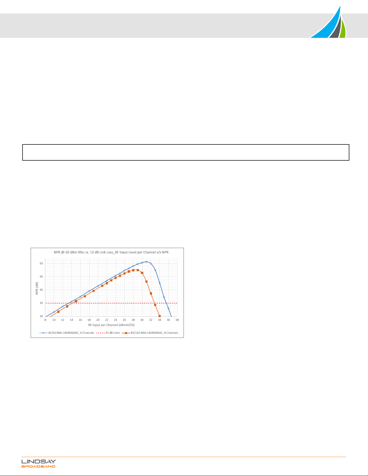
9. The upstream RF input range for the LBON300AC is 15-35 dBmV per channel (digital channel level) for the 42/54 MHz LBON300AC, and 15-33 dBmV per
channel (digital channel level) for the 85/102 MHz LBON300AC. These upstream levels are assumed with the condition that a 42/54 MHz split unit will have 4
equally loaded channels in the upstream band, and the 85/102 MHz split will have 8 equally loaded channels in the upstream band. If using a different number of
channels from what is mentioned above, compensate for total RF power. The total RF input level to the LBON300AC (for all channels combined) should not exceed
more than 40 dBmV (digital channel level). More than 40 dBmV (digital channel level) total upstream RF input may cause laser clipping and saturation on the
LBON300AC. Use the following formula to calculate total RF power: Total RF power = RF power per channel + [10* log (# of channels)].
10. Refer to the NPR plot below to better understand the RF input levels to the LBON300AC.
11. For optimum performance in the upstream direction, make sure the LBON300AC is operated with RF input levels to the left side of the NPR peak. Operating at
RF input levels to the left side of the NPR peak will provide the best MER/BER performance while assuring the laser saturation and clipping does not occur on the
RFoG ONU transmitter.
12. This completes the reverse path setup for the LBON300AC RFoG ONU.
13. If you have any more questions regarding the LBON300AC setup, please contact Lindsay Broadband for support.
NOTE: The RF levels mentioned in this manual are analog channel levels, unless specified. For digital channels assume 6 dB less to that of
analog channels.
11. The F-port labelled “RF OUT” is the bi-directional RF input and output port for the LBON300AC RFoG ONU.
12. The “TEST -20 dB” port is a bi-directional -20 dB TP that can be used to test RF input and output levels. When not in use, please terminate this -20 dB TP with a 75
ohm terminator.
13. When using the -20 dB TP to measure the RF input/output levels, make sure the RF OUT port is terminated to 75 ohm. Please note the levels from -20 dB TP will
be 20 dB lower than the RF OUT port.
COMPLETING THE INSTALLATION
1. Record the input and output levels for the station in both upstream and downstream for reference.
2. Make sure the cables are routed properly and all connections are secured.
3. Ensure the optical fiber cable is not pinched and does not have sharp bends.
TROUBLESHOOTING GUIDELINES
1. No Power on the LBON300AC ONU.
a. Check the powering coaxial cable and connections for intermittent connections.
b. Check the output of the power adapter for proper DC voltage (12-15 VDC). It is normal for a linear power pack to have more than 15 VDC output when
unloaded. It should not be more than 20 VDC when unloaded. When the LBON300AC is connected to this unloaded power pack, the output voltage will drop
within 12-15 VDC specification.
c. Check with a different 12 VDC or 15 VDC power pack that is at least rated for more than 500 mA.
d. Try powering via the RF OUT/PWR IN port using a power inserter.
LBON300AC Series 1 GHz Customer Premise RFoG ONU Installation & Operation Manual
TROUBLESHOOTING GUIDELINES CONT'D.
2. Low or no downstream RF output level.
a. Verify the optical receive level on the LBON300AC is within range (-6 dBm to +2 dBm, 3.5% OMI level and 1540-1565 nm).
b. Using a fiber inspection scope, check the optical connector and adapter. Make sure the optical connection is clean.
c. If the optical input is within range, the OPT IN LED will be illuminated. Verify that the OPT IN LED is illuminated. Use a DC voltage meter to measure the 1
mW/ 1V TP on the ONU. Refer to step #10 and table under the OPTICAL, RF & POWER CONNECTIONS section of this manual.
d. Check for intermittent connections or pinched fibers.
3. Low or no upstream transmit level.
a. Verify the upstream RF input level is within the LBON300AC upstream frequency range (5-42 MHz or 5-85 MHz) and higher than 15 dBmV ± 1 dB.
b. Use a CW carrier for injection to keep the transmit laser ON.
c. Inject either from the RF OUT port or using the bi-directional -20 dB TP. Make sure to compensate 20 dB if using the -20 dB TP to inject carrier.
d. If the upstream RF input is within RF input range, then the OPT OUT LED will illuminate. Verify the OPT OUT LED is ON.
e. When the OPT OUT LED is ON, connect an optical power meter to the OPT IN/OUT port. Using the optical power meter at the proper upstream wavelength,
verify the optical output of the LBON300AC directly from OPT IN/OUT port is ≥ 2.7 dBm.
f. Check for intermittent connections.
4. If the problem is still not solved, replace, and try with another ONU.
5. If the problem still exists, contact Lindsay Broadband for support. Do not open the LBON300AC as it will void the warranty.
ORDERING INFORMATION
Fwd Total Return Laser TX Optical TX Sub-Split Power
Output Level Input Power Type Power Connector Wavelength Adaptor
LBON300AC -xx xx -D-x-xx -xx -xx -xx
18 = 18 dBmV 25 = 25 dBmV D = DFB 2 = 2 mW SA = SC/APC 31 = 1310 nm 45 = 42/54 00 = None
20 = 20 dBmV 30 = 30 dBmV 3 = 3 mW SU = SC/UPC 41 = 1410 nm 68 = 65/85 01 = N. America
36 = 36 dBmV 43 = 1430 nm 81 = 85/102 02 = Europe
45 = 1450 nm
47 = 1470 nm
49 = 1490 nm
51 = 1510 nm
53 = 1530 nm
55 = 1550 nm
57 = 1570 nm
59 = 1590 nm
61 = 1610 nm
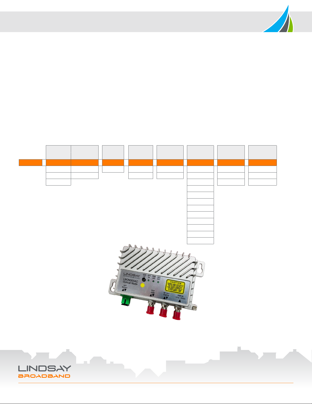
LBON300AC
(front angled view)
2-2035 Fisher Dr, Peterborough, ON K9J 6X6 Canada
+1.705.742.1350 • 1.800.465.7046 • support@lindsaybb.com • lindsaybb.com
© 2021 Lindsay Broadband Inc. All rights reserved. Printed in Canada. Non-Lindsay Broadband product marks,
service marks, and company names in this document are the property of their respective owners. All information is subject to change without notice.
Rev. 05/21 (LBB0355) • Page 4 of 4
This manual suits for next models
1
Other Lindsay Broadband Network Hardware manuals


Popular Network Hardware manuals by other brands


PairGain
PairGain HLU-319 manual

Cisco
Cisco DS-X9530-SF1-K9 - Supervisor-1 Module - Control... Configuration guide

Crestron
Crestron AV2 Operation guide

Cabletron Systems
Cabletron Systems BRIM-T6 user guide

Honeywell
Honeywell Notifier NFN-GW-EM-3 Installation and operation manual

Silex technology
Silex technology MNS-300EM Command manual


