Lindsay Broadband SMHAP User manual

Page 1 of 14
Rev. 07/19 (LBB0132)
SMHAP MANUAL
(UAP-AC-MESH)

Page 2 of 14
SMHAP UAP-AC-MESH Manual
Rev. 07/19 (LBB0132)
Contents
IMPORTANT SAFETY AND INSTALLATION WARNINGS
.................................................. 3
SECTION 1
PRODUCT DESCRIPTION
................................................................... 4
1.1 Introduction .............................................................................................................................................. 4
1.2 General Description............................................................................................................................... 4
1.3 Housing ..................................................................................................................................................... 4
1.4 Power Supply Lid.................................................................................................................................... 4
1.5 Main Board (HFC Interface) ................................................................................................................ 5
1.6 Block Diagram ......................................................................................................................................... 6
SECTION 2
COMPONENT IDENTIFICATION
.......................................................... 7
SECTION 3
INSTALLATION
................................................................................... 8
3.1 Pre-Installation........................................................................................................................................ 8
3.2 Site Selection .......................................................................................................................................... 9
3.3 Installation ................................................................................................................................................ 9
3.4 Installation Diagrams ..........................................................................................................................10
SECTION 4
SMHAP Specifications
....................................................................... 11
4.1 Housing Dimensions............................................................................................................................11
4.2 Table of Specifications............................................................................................................................12
SECTION 5
ACCESS POINT CONFIGURATION
...................................................... 14
5.1 Overview.......................................................................................................................................................14
5.2 Discovery......................................................................................................................................................14

Page 3 of 14
SMHAP UAP-AC-MESH Manual
Rev. 07/19 (LBB0132)
IMPORTANT SAFETY AND INSTALLATION WARNINGS
Caution! Exposure to Radio Frequency Radiation
The radiated output power of the SMHAP is far below the FCC radio frequency exposure limits.
Nevertheless, the SMHAP should be used in a manner that minimizes the potential for human
contact during normal operation. When using this device, a certain separation distance between
the antenna and nearby persons has to be kept to ensure RF exposure compliance.
The antenna(s) shall be placed in a manner that minimizes the potential for human contact during
normal operation. To avoid the possibility of exceeding the FCC radio frequency exposure limits,
human proximity to the antenna(s) shall not be less than 20 cm (8 inches) during normal operation.
IMPORTANT SAFETY AND INSTALLATION WARNINGS
WARNING: DO NOT ATTEMPT TO SERVICE THIS PRODUCT YOURSELF AS OPENING OR
REMOVING COVERS MAY EXPOSE YOU TO DANGEROUS VOLTAGES OR OTHER HAZARDS.
REFER ALL SERVICING TO QUALIFIED SERVICE PERSONNEL.
MOUNTING:
Mount this product only as described in the installation instruct ions, otherwise it may fall causing
serious personal injury and/or damage the unit. Use only with the brackets supplied with the
product. Do not use attachments not recommended for this product as they may cause hazards.
SERVICING:
Remove power from this access controller and refer servicing to qualified personnel under the
following conditions:
1. If the inside of the station has been exposed to rain or water.
2. If the stat ion does not operate normally by following the operating
instructions. Adjust only those controls that are covered by the operating
instructions as an improper adjustment of the controls may result in damage
and will often require extensive work by a qualified technician to restore the
unit to its normal operation.
3. If the unit has been dropped or the chassis has been damaged.
4. If the unit exhibits a distinct change in performance.
REPLACEMENT PARTS:
When replacement parts are required, be sure the service technician has used replacement parts
specified by the manufacturer or have the same characteristics as the original part. Unauthorized
substitutions may result in fire, electric shock or other hazards.
SERVICE DEPOT:
Canada: Lindsay Broadband Inc.
2-2035 Fisher Drive
Peterborough, Ontario K9J 6X6
(705) 742-1350

Page 4 of 14
SMHAP UAP-AC-MESH Manual
Rev. 07/19 (LBB0132)
SECTION 1 PRODUCT DESCRIPTION
1.1 Introduction
This section gives a full product description and a block diagram. Check for any separately
included information that is specific to the Access Point and Cable Modem in your SMHAP.
1.2 General Description
The SMHAP is an integrated, standards based, hardened solution for outdoor 802.11
based access to the HFC DOCSIS®network. It can be connected to the HFC network
through any power-passing tap, splitter, or coupler. This one-piece solution consists
of a discrete cable modem and a discrete access point. Each piece is configured
separately. The cable modem is configured by your DOCSIS provisioning software. The
UniFi AP is a dual band access point integrated with dual band antennas. See Section
Five for information on centralized configuration and management of the AP.
The modem within this SMHAP, in conjunction with the standard
Cablelabs SNMP MIB, can also be used to monitor plant conditions.
1.3 Housing
A rugged die cast aluminum housing of clamshell design is used. Externally, the housing
base has installation mounts, type N antenna connectors, a type F test point connector,
and a 5/8” port to interface with the HFC network using a KS connector. Internally, the
housing bottom harbors the HFC interface board and the access point. The power supply
and cable modem are housed in the lid. Dual gaskets provide for EMI isolation and an
airtight seal to 15psi. The housing can be strand mounted. An optional hardware kit for
wall, mast or pedestal mounting is available. The station size is approximately 11.5 x 8.5 x
5 inches (290 x 220 x 130 mm). Its weight is around 6.5 pounds (3 kg).
1.4 Power Supply Lid
The power supply and cable modem are housed separately in the station lid. For ease
of removal the lid/base hinge system uses a “lift off” style where two pivot pins cast
as part of the lid slide through fixed rings cast as part of the base. A small screw and
washer lock the assembly together.
The power supply lid interconnects to the housing base with a harness of power, RF,
and Ethernet cables. A high efficiency switch mode power supply is used. Filtering to
prevent the switching regulator noise from reaching the AC and DC lines is provided.

Page 5 of 14
SMHAP UAP-AC-MESH Manual
Rev. 07/19 (LBB0132)
1.5 Main Board (HFC Interface)
The main circuit board, which is located in the housing base, provides the interface to
the HFC Network. The following features are provided:
a) An AC/RF filter is used to separate de AC power from the RF carriers.
b) Plug-in SVP type surge protection.
c) A socket for optional solid-state crowbar surge protection.
d) Sockets for the separate padding of forward and reverse signals.
e) Test point. 20dB coupling of forward and reverse power at the cable modem
port.
f) A power interrupt to disconnect ac power for safe lid removal.

Page 6 of 14
SMHAP UAP-AC-MESH Manual
Rev. 07/19 (LBB0132)
1.6 Block Diagram

Page 7 of 14
SMHAP UAP-AC-MESH Manual
Rev. 07/19 (LBB0132)
SECTION 2 COMPONENT IDENTIFICATION
Antenna 1
Antenna 2
RF Test Point
RF/AC Input
Cable Modem
EMI Gasket
Water Seal
12V / 48V
Power Supply
UAP-AC-MESH
Surge Arrestor
Forward Pad
POE Inserter
AC Interrupt
Reverse Pad

Page 8 of 14
SMHAP UAP-AC-MESH Manual
Rev. 07/19 (LBB0132)
SECTION 3 INSTALLATION
Installation of the SMHAP is similar to the installation of a line extender, or tap, or
other piece of CATV equipment. The SMHAP UAP AC MESH be connected to any
power passing tap, splitter, or coupler.
3.1 Pre-Installation
Upon receipt of the SMHAP, inspect the carton for any external damage. If damage
is present inspect the SMHAP exterior for damage. Report any apparent damage
to the shipping agent and Lindsay Broadband sales office.
Pad values can be determined ahead of time. The loss of the HFC interface board
should be allowed for when calculating pad values. There is 4 dB of loss in the
reverse direction, and 5 dB of loss in the forward direction. The forward pad should
be selected so that power incident on the cable modem is 0 dBmV (5 dBmV at the
Gateway KS connection). For best return path S/N, the reverse pad should be
selected so as to have the cable modem operate near its maximum output level
(-47 to –50 dBmV).
The cable modem can be provisioned ahead of time using the MAC address located on the
label on the outside of the power lid.
A 1/2” wrench is needed for both the strand clamp and housing bolts.

Page 9 of 14
SMHAP UAP-AC-MESH Manual
Rev. 07/19 (LBB0132)
3.2 Site Selection
The SMHAP must be mounted so that it has an un-obstructed view of the target area. The
SMHAP can obtain its power from any nearby power passing tap, splitter, or coupler. An
SMHAP with a UniFi AP can consume up to 23W of power.
3.3 Installation
Installation of the SMHAP is similar to the installation of a line extender, or tap, or other
piece of CATV equipment. Use the diagrams in this section as guide to the installation,
and the diagrams in section 2 to help locate the components referred to in the following
instructions.
1. Mount the SMHAP in its final location. If using hanger brackets, the existing strand
clamps should be left in place to act as spacer allowing the same bolts to be used (See
section 3.4).
2. Pull the AC interrupt at the upstream coupler.
3. Open the lid of the SMHAP, by undoing the 4 bolts using a 13 mm wrench.
4. Replace the two 0 dB RF pads with pad values that were determined before entering
the field.
5. Make a coaxial connection to your HFC network at the upstream coupler.
6. Mount and aim the antennas. All omni -directional antennas should be orientated
vertically (pointing downward). Sector antennas should be mounted so that the RF
connector is at the bottom.
7. Re-install the AC interrupt. Indicator LEDS on the cable modem and radio should
indicate startup and discovery of their respective networks. (Refer to the cable modem
installation guide for more information.)
8. The forward and reverse RF levels at the cable modem can be measured at the single
test point. Readings are -20dB relative to the cable modem F connector. Make
adjustments to pad values as required.
9. Silicone Grease can be applied to the exposed part of the o-ring before swinging the lid
back into place. This will reduce any tendency of the o-ring to stick to the lid and ensure a
weather-tight seal. To be clear, use Silicone Grease, not Silicone Sealant, nor any other
type of Grease.
10. If the EMI gasket has any frayed or loose ends tuck them back into the channel and
close the lid while ensuring that the wire harness does not interfere with the base and lid
sealing surfaces.
11. Using a torque wrench with a 13 mm socket, tighten the lid bolts gradually and
alternate diagonally to avoid stress or warp on the housing sealing surfaces. The lid bolts
should be tightened to the specified 17-ft LB or 24 Nm torque to ensure that the EMI
specification is met. The required torque is easily met by using the box end of a
combination wrench, but cannot be reached using a nut driver.
Page 10 of 14
SMHAP UAP-AC-MESH Manual
Rev. 07/19 (LBB0132)
12. Tape all connections to reduce moisture intake.
13. Before the AP becomes fully functional it must “discover” the controller. See
section 5.2 for more information.
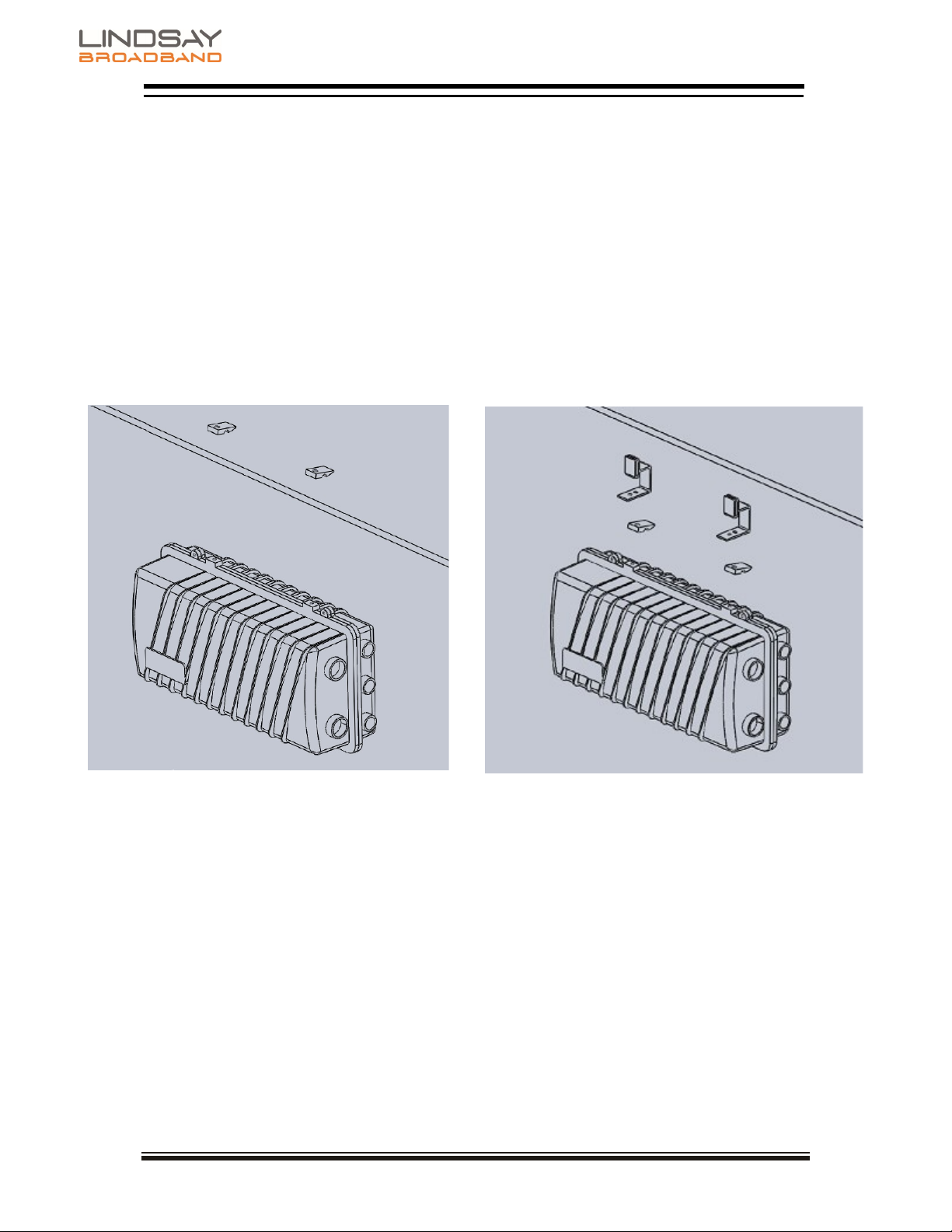
3.4 Installation Diagrams
Strand Mount Strand Mount with Hanger
Brackets

SMHAP UAP-AC-MESH Manual
Page 11 of 14
Rev. 07/19 (LBB0132)
SECTION 4 SMHAP Specifications
4.1 Housing Dimensions

SMHAP UAP-AC-MESH Manual
Page 12 of 14
Rev. 07/19 (LBB0132)
4.2 Table of Specifications
Parameter
Specification
UAP-AC-M
Networking Interface
(1) 10/100/1000 ethernet port
Buttons
Reset
Antennas
(2) External Dual-Band
Omni Antennas
2.4 GHz
7 dBi
5 GHz
6 dBi
Wi-Fi
®
Standards
802.11 a/b/g/n/r/k/v/ac
Wireless Security
WEP, WPA-PSK, WPA-Enterprise
(WPA/WPA2, TKIP/AES)
BSSID
Up to 8 per radio
Certifications
CE, FCC, IC
TX Power
2.4 GHz
20 dBm
5 GHz
Advanced Traffic Management of AP
VLAN
802.11Q
Advanced QoS
Per-user rate limiting
Guest Traffic Isolation
Supported
WMM
Voice, video, best effort & background
Concurrent Clients
250+
Cable Modem (4)
Standards
DOCSIS
®
(2.0, 1.x & 3.1 compatible)
Band Plan
DOCSIS (annex A & annex B options)
Network Configuration & Management
TFTP, SNMP (V2c, V3), Telnet, HTTP
Input Impedance
75 Ω
Privacy
BPI+, EAE, SSD
Downstream Modulation
64 or 256 QAM
RF Input Sensitivity(1)
Modem F port
+15 to -15 dBmV (-10 dBmV for 256 QAM)
Housing 5/8" port
+20 to -10 dBmV (-5 dBmV for 256 QAM)
Upstream Modulation
QPSK & 8, 16, 32, 64, 128 QAM
Max. Transmit Power
(ATDMA QAM 64)(1)
Modem F Port
54 dBmV (47 to 50 dBmV recommended)
Housing 5/8" port
49 dBmV (43 to 46 dBmV recommended)
HFC Interface
Return Loss (2)
Min., with 75 Ω termination
16 dB
Min., when terminated by
modem
10 dB
Insertion Loss
(1)
5 dB (+/-1 dB) (4 dB for upstream)
Pad Type JXP, separate fwd & rev 0 to 20 dB
EMI Isolation
100 dB (5 to 100 MHz)
Surge Withstand (HFC) ANSI-IEEE C62.41 Category B3 (6 KV)
(GAS tube or solid state crowbar option)

SMHAP UAP-AC-MESH Manual
Page 13 of 14
Rev. 07/19 (LBB0132)
Modem
Model
Per customer specification
Protocol
DOCSIS 1.1/2.0/3.0/3.1
Management
SNMP v1, v2C, v3, HTTP
Power, Environmental & Physical
Power Supply
Input Voltage Range (3) Quasi square
33-36 to 100 VAC
55-58 to 100 VAC
Efficiency
80% (min.)
Upstream Noise & Spurious
-50 dBmV (max., 5-1000 MHz)
Ingress Protection
IP68 (15 PSI for 10 seconds)
SMHAP
Power Method
Psuedo Sine
Power Consumption
23 W (max.)
Operating Temperature
-40°C to +60°C (-40°F to +140°F)
Ingress Protection
IP68 (15 PSI for 10 seconds)
Dimensions (H x W x D)
8.5”H x 11.5”W x 5.0”D (21.0H x 29.0W x 12.0D cm)
Weight
7.0 lb (3.2 kg)
Notes:
(1)
Levels reported by the modem management interfaces reference the modem F port.Levels at
the Gateway 5/8” KS port incorporate the internal 5dB loss of the HFC Interface.
(2)
Overall return loss is dependent on the modem.
(3)
Two voltage range options are available.
(4)
Typical. Specification will vary depending on which model of modem is ordered

SMHAP UAP-AC-MESH Manual
Page 14 of 14
Rev. 07/19 (LBB0132)
SECTION 5 ACCESS POINT CONFIGURATION
5.1 Overview
The UniFi AP within your SMHAP is configured and managed using the UniFi Controller, a
wireless network management software solution from Ubiquiti Networks™. The freely
available controller software can be installed on any computer that is using OS X, Linux, or
Windows 7/8/10 operating system. The management station can be local or remote to the
wireless network. Once the UniFi software is installed on the management station it can be
accessed from anywhere using a web browser.
The UAP-AC-M requires the UniFi Controller v5.4 or higher, available at:
www.ubnt.com/download/unifi
5.2 Discovery
The UniFi AP has no trouble finding the management station when they are both connected to
the same local (layer 2) network. Without help, discovery will not work in a routed (layer 3)
network.
To enable fully automatic discovery in a routed network, either the DNS server or the DHCP
server must be configured to pass the IP address of the management station to the AP. The
DNS and DHCP methods are explained at https://help.ubnt.com/hc/en-us/articles/204909754
Either of these methods is recommended when a large number of APs are to be deployed.
When there is no access to the DHCP or DNS servers, or if only a few APs are to be
deployed, there are manual methods of telling the AP the IP address of the controller. The
simplest way is explained at http://dl-origin.ubnt.com/guides/UniFi/UniFi_AP-AC-M_QSG.pdf
Basically:
•Install the SMHAP at its final location.
•Once the SMHAP is powered, the AP will boot and will obtain its’ IP provisioning by
•DHCP.
•Determine the IP address of the AP using the console for your DOCSIS provisioning
•software. The AP will be listed as a CPE behind the cable modem.
•Connect to the AP using SSH. This can be done from any location, provided that a
public
•IP was issued to the AP.
•Login name is “ubnt”, and the password is also “ubnt”.
•Once you are logged in type “set-inform http://<ip-of-controller>:8080/inform”,
substituting in the actual IP address of the controller.
•At the controller click on the “Access Points” tab, The AP will be listed as “Pending
•Approval”. You may have to wait a couple of minutes for this, or use the refresh
button.
•“Adopt” the AP. The controller will show that the AP has the status of “Adopting”.
•Return to your SSH session and enter the “set-inform” command a second time. (Hint:
•use the up arrow). The AP will reboot, closing your SSH session.
•The controller will eventually list the AP as “connected”.
This manual suits for next models
1
Table of contents
Popular Wireless Access Point manuals by other brands

Ruckus Wireless
Ruckus Wireless ZoneFlex 7441 Quick setup guide

Cisco
Cisco AT&T U-VERSE VEN401 Quick reference guide

Huawei
Huawei eAN3810A Hardware installation guide

Extreme Networks
Extreme Networks ExtremeWireless AP302W installation guide

LEGRAND
LEGRAND DA1101 owner's manual

Comtrend Corporation
Comtrend Corporation WAP-PC1750W Quick installation guide


